Fairmont Smart - Heating Blumfeldt - Free user manual and instructions
Find the device manual for free Fairmont Smart Blumfeldt in PDF.

User questions about Fairmont Smart Blumfeldt
0 question about this device. Answer the ones you know or ask your own.
Ask a new question about this device
Download the instructions for your Heating in PDF format for free! Find your manual Fairmont Smart - Blumfeldt and take your electronic device back in hand. On this page are published all the documents necessary for the use of your device. Fairmont Smart by Blumfeldt.
USER MANUAL Fairmont Smart Blumfeldt
natural_image
Abstract green circular logo with three curved segments (no text or symbols)
natural_image
Abstract green circular logo with two leaf-like shapes (no text or symbols)
natural_image
Abstract green circular logo with three leaf-like shapes forming a Y-shape (no text or symbols)Fairmont Smart
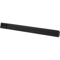
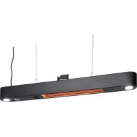
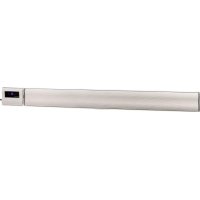
Heizkörper
Radiator
Radiateur
Radiador
Radiatore
10045588 10045589
text_image
QR code image containing encoded data, no visible human-readable textINSTALLATION DES THERMOSTATS
flowchart
graph TD
    A["Left panel: Lateral structure"] --> B["Top view of mechanical assembly"]
    B --> C["Downward arrow to right panel"]
    C --> D["Bottom view of mechanical assembly"]
    style A fill:#f9f,stroke:#333
    style B fill:#ccf,stroke:#333
    style C fill:#cfc,stroke:#333
    style D fill:#fcc,stroke:#333
natural_image
Black rounded square icon with white icons for time, Wi-Fi, and signal symbols (no text or numbers)text_image
80.00° SAROS- Timer einstellen
natural_image
Symbol of a trash bin crossed with a diagonal line, no text or numbers presentBerlin Brands Group UK Limited PO Box 42
272 Kensington High Street London, W8 6ND United Kingdom
Congratulations on your purchase. Please read the following instructions carefully and follow them to prevent potential damage. We accept no liability for damage caused by disregarding the instructions or improper use. Please scan the QR code to access the latest operating instructions and for further information about the product.

text_image
QR code image containing encoded data, no visible human-readable textCONTENTS
Safety instructions 28
Required tools 29
Scope of delivery 29
Installing the thermostat 30
Installing the radiator 31
Cleaning and care of the radiator 34
Operating the thermostat 35
Device control via smartphone 44
Internal parameter setting 46
Product Data Sheet 48
Disposal considerations 50
Declaration of conformity 50
TECHNICAL DATA
| Article number 10045588 10045589 | ||
| Dimensions of the radiator (H x W) 80 | x 45 cm 107 x 50 cm | |
| Power supply (thermostat) 230 V ~ 50 | Hz | |
SAFETY INSTRUCTIONS
- Follow the installation instructions carefully to ensure that the unit is properly attached to the wall.
- To avoid a possible fire hazard, it is important that the appliance is installed in accordance with the specifications given in the instructions.
- The radiator is intended for indoor use only. Do not place the heater in a shower, steam room or any other place where it may be exposed to water.
Child safety tips
- Please note that you are 100% responsible for the safety of your child at home. As soon as the radiator is installed, it can become a danger for children, as
(a) that radiator is not designed to support unreasonable additional weight, such as that of a child; and
b) the radiator becomes hot during use.
- For this reason, children must not climb on, reach for or play with the radiator or the heating rails as this can lead to accidents or injuries, e.g. due to heat, falling down or tearing the radiator off the wall.
Installation instructions
- Observe all local regulations for sanitary installations and buildings.
- Close the main water pipe.
- Read these instructions carefully to ensure proper installation.
- Make sure that the parts listed below are included in the scope of delivery.
REQUIRED TOOLS
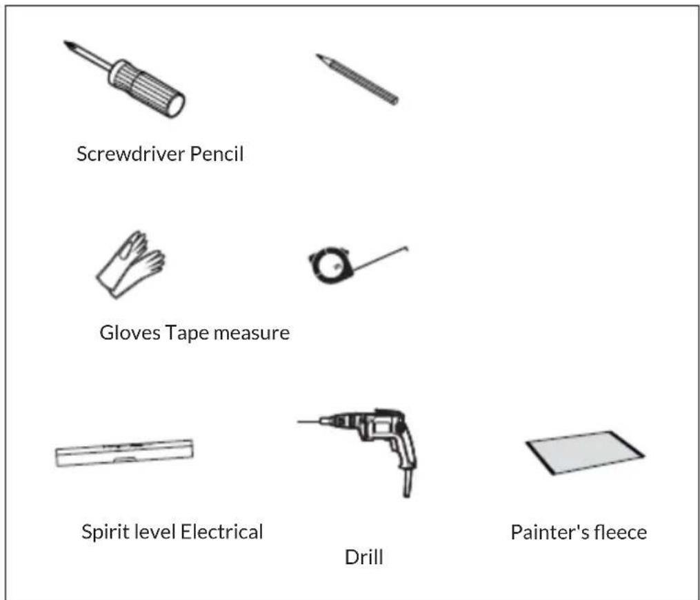
text_image
Screwdriver Pencil Gloves Tape measure Spirit level Electrical Drill Painter's fleeceSCOPE OF DELIVERY
| Radiator (1x) Long screw (4x) | Dowel (4x) | |
10045588 10045589  | [SCW0] | 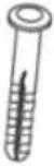 |
| Wall mount (4x) Rubber washer (2x) | ||
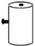 | 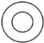 | |
| PTFE tape Wrench | ||
| [HAGS] | 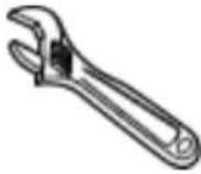 | |
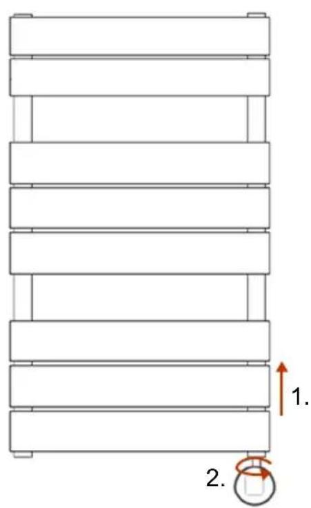
INSTALLING THE THERMOSTAT
Note: Disconnect the device from power supply before proceeding with installation or maintenance.
text_image
1. 2.- Loosen the screw on the underside of the radiator.
- Insert the thermostat into the threaded hole at the bottom of the radiator.
- Turn the thermostat until it is fully secured in the radiator.
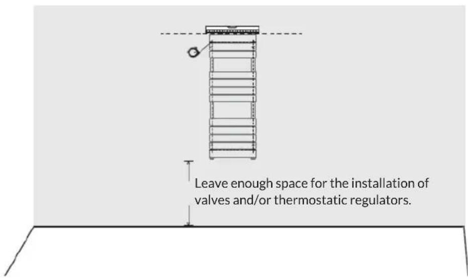
INSTALLING THE RADIATOR
Step 1
text_image
Leave enough space for the installation of valves and/or thermostatic regulators.- Position the radiator in the desired place, check the horizontal alignment and mark four equal positions for the brackets.
• Make sure that the radiator is mounted vertically. - Before installation, place a painter's fleece on the floor to prevent the loss of small parts.
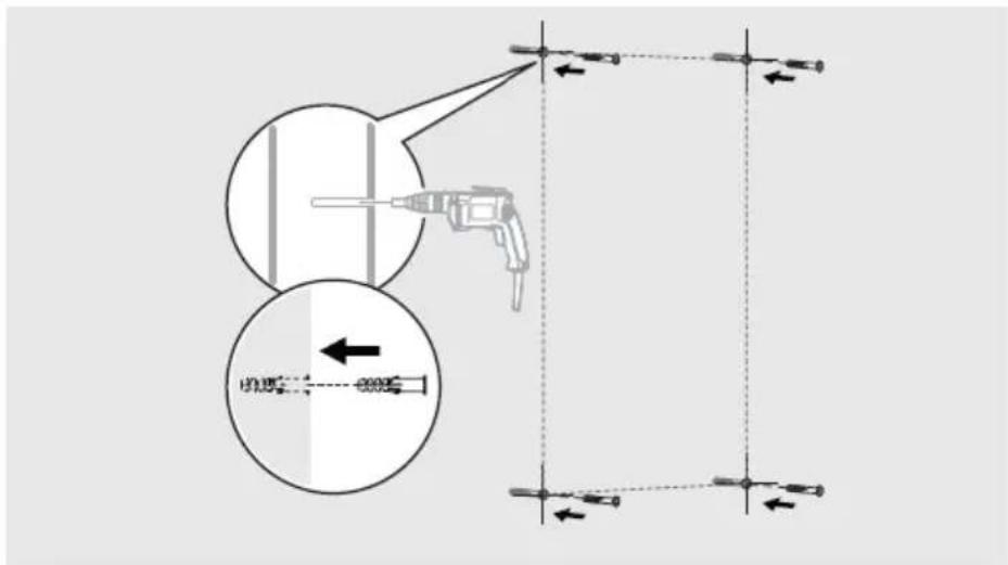
Step 2
text_image
Diagram illustrating a drill bit setup with labeled components and directional arrows, including a magnified inset showing the drill bit path.- Drill holes in the wall and insert dowels.
Note: For false ceilings or stud walls, you can purchase other fixings at a DIY store.
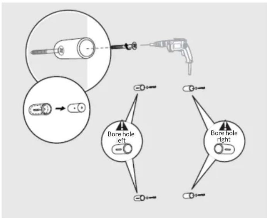
Step 3
flowchart
graph TD
    A["Top view: Bore hole left"] --> B["Arrow pointing to a cylindrical object"]
    C["Bottom view: Bore hole right"] --> D["Arrow pointing to a cylindrical object"]
    style A fill:#f9f,stroke:#333
    style C fill:#f9f,stroke:#333
    style B fill:#ccf,stroke:#333
    style D fill:#ccf,stroke:#333
- Separate the two bracket parts and attach the larger one to the wall.
Step 4
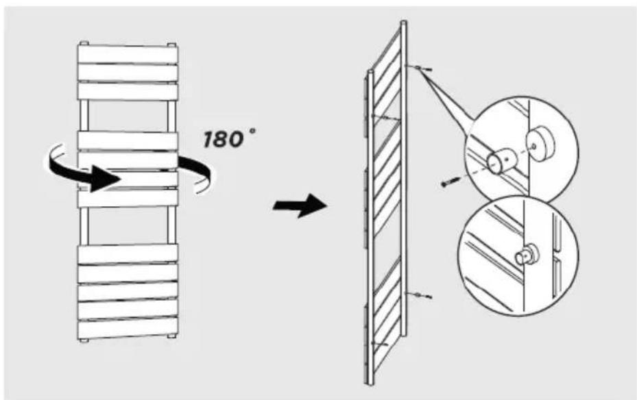
text_image
180°- Attach the smaller bracket piece to the back of the radiator.
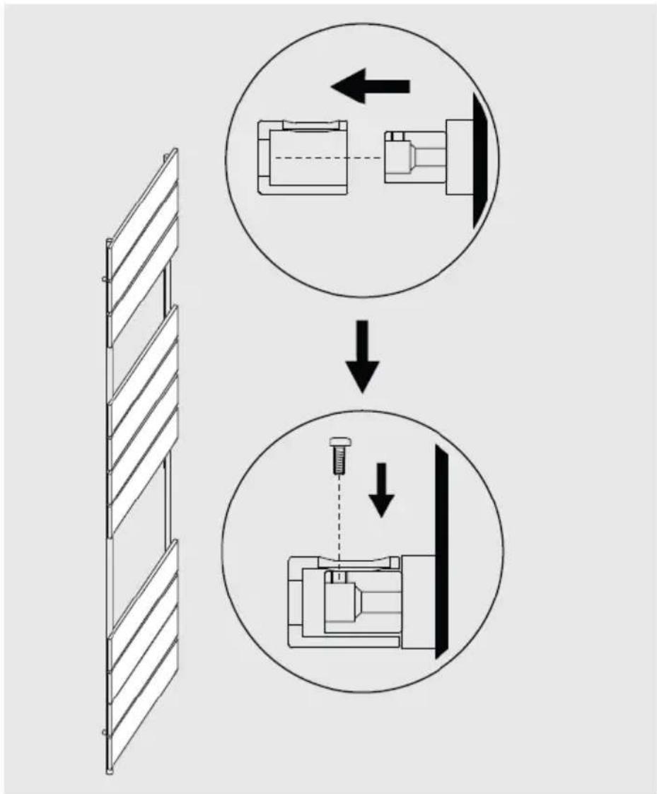
Step 5
flowchart
graph TD
    A["Left panel: Lateral structure"] --> B["Top view of mechanical assembly"]
    B --> C["Downward arrow to right panel"]
    C --> D["Bottom view of mechanical assembly"]
    style A fill:#f9f,stroke:#333
    style B fill:#ccf,stroke:#333
    style C fill:#cfc,stroke:#333
    style D fill:#fcc,stroke:#333
- Attach the radiator to the wall by aligning the brackets and tighten the small screw when it is in position.
CLEANING AND CARE OF THE RADIATOR
- Wipe the surface clean with a soft damp cloth.
- Never use abrasive cleaners on this product as these will damage the surface.
- Radiators are made of steel and should therefore not be cleaned with corrosive or abrasive cleaning agents.
OPERATING THE THERMOSTAT
| Power supply 230 V ~ 50 Hz | |
| Temperature settings 7-30 | °C (room temperature)40-80 °C (radiator surface temperature) |
| Operating modes Comfort | mode, economy mode, frost protection mode, weekly schedule, timed heating mode (surface) |
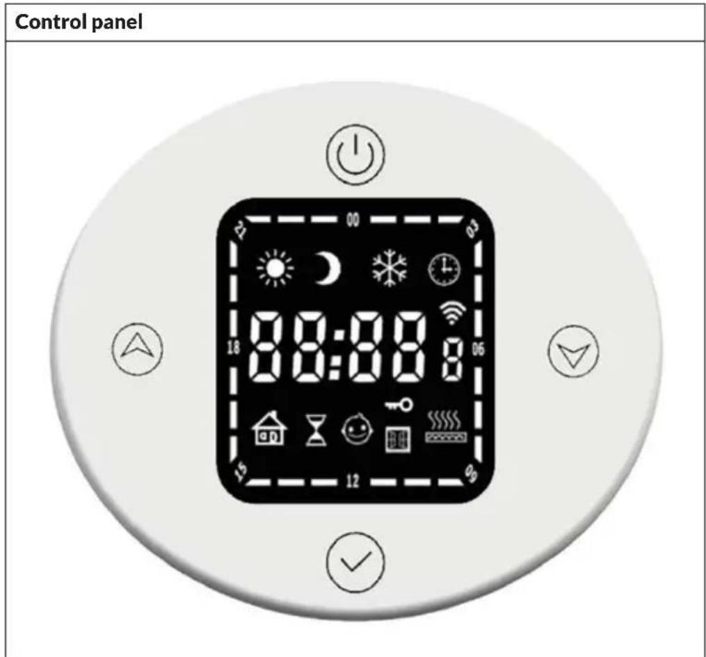
text_image
Control panel 00:00:00 18 00:00:00 15 12 06| Buttons Displays | |||||
 | On/off Comf |  | ode Heat mode timer |  | |
 | Mode Econo |  | ode Child safety lock |  | |
 | Up (+) |  | Frost protection mode |  | Time / temperature |
 | Down (-) We |  | program WLAN |  | |
Basic functions
- Turn on: Briefly press the on/off button ⏻ to turn on the thermostat. When the device is switched off, it does not respond to pressing any other button and the time is shown on the display.
- Mode switching: Quickly press the mode button to switch between the different modes in the following order: comfort mode > economy mode > frost protection mode > timer mode > heating mode timer > ...
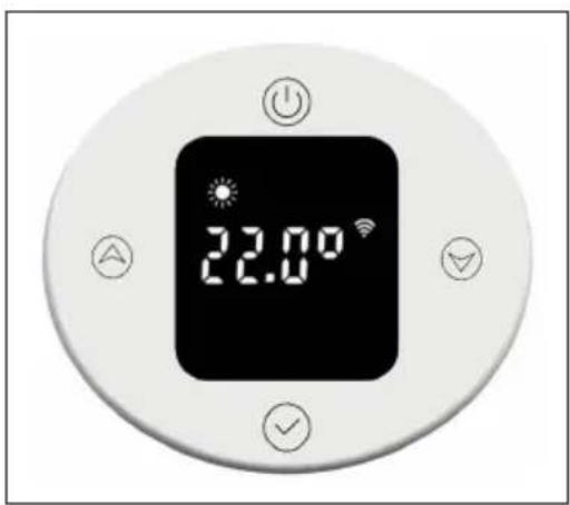
Comfort mode
Briefly press the on/off button ⏻ to enter comfort mode. The default is a room temperature of 22 °C and a radiator surface temperature of 80 °C. The temperature setting for the radiator surface can be adjusted in the range of 40-80 °C.

text_image
22.00°To set the room temperature, briefly press the up or down button. The temperature can be adjusted in the range of 7-30 °C in 0.5 °C increments. Pressing and holding the button speeds up the setting.
Economy mode
Briefly press the mode button √ to switch to economy mode. A room temperature of 22 °C and a radiator surface temperature of 60 °C are preset. The temperature setting for the radiator surface can be adjusted in the range of 40-60 °C.
text_image
22.00°To set the room temperature, briefly press the up or down button. The temperature can be adjusted in the range of 7-30 °C in 0.5 °C increments. Pressing and holding the button speeds up the setting. The maximum temperature setting must not exceed that of comfort mode.
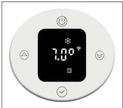
Frost protection mode
Briefly press the mode button √ to switch to frost protection mode. The temperature setting of 7°C cannot be changed.
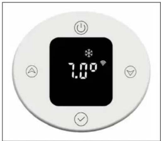
text_image
1.00°Timer mode
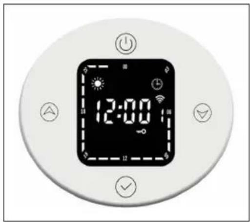
Briefly press the mode button √ to switch to timer mode. When using for the first time, you must set the time or connect to the internet to update the time automatically. In the timer mode, you can set the time, the day of the week and the weekly program.
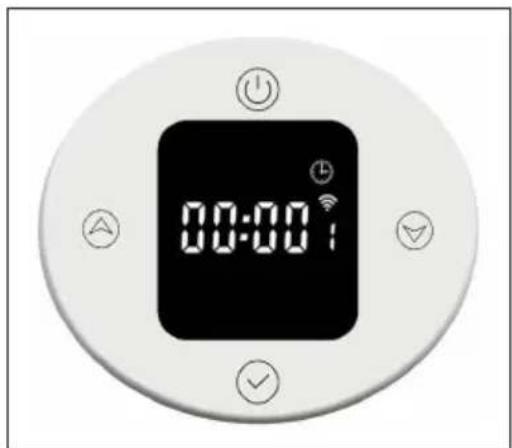
text_image
00:00Setting the time
- Hour setting:
To set the hour, press and hold the mode button √
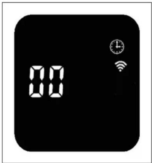
text_image
88 88Briefly press the up or down button to adjust the hour setting in the range of 0-23 h in 1-hour increments. After 30 seconds without input, the hour setting is automatically terminated and the display changes to the minute setting.
- Minute setting:
To set the minute, briefly press the mode button √
Briefly press the up or down button to adjust the minute setting in the range of 0-59 minutes in 1-minute increments. After 30 seconds without input, the minute setting is automatically terminated and the display changes to the weekday setting.
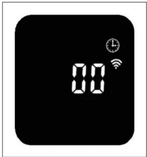
text_image
8:00Weekday setting:
To set the weekday, briefly press the mode button √
Briefly press the up ▼ down button to adjust the weekday setting in the range of 1 to 7 days in 1-day increments. After 30 seconds without input, the weekday setting is automatically terminated and the display changes to the week program setting.
natural_image
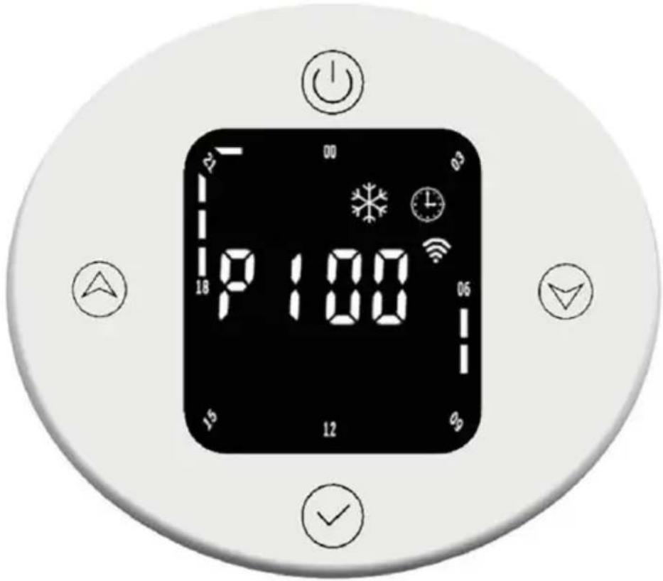
Black square icon with white icons for time, Wi-Fi, and alarm (no text or symbols)Setting weekly program:
| View the weekly program | |
| P1 Day of the week (adjustable range: 1-7 days) | |
| 00 Hour (adjustable range: 00:00 - 23:00) | |
 | The display shows the symbol of the current operating mode. |
| Preset for P1 to P5 (Monday to Friday) | |
 | |
| 22:00 - 5:59 | Frost protection mode |
| 6:00-7:59 | Comfort mode |
| 8:00-17:59 | Frost protection mode |
| 18:00-21:59 | Comfort mode |
| Preset for P6 to P7 (Saturday to Sunday) | |
| 22:00-7:59 Frost protection mode | |
| 8:00-9:59 Comfort mode | |
| 10:00-16:59 Frost protection mode | |
| 17:00-21:59Comfort mode | |
Adjusting week program settings
Briefly press the mode button to select the time-dependent operation mode (comfort mode, economy mode, frost protection mode). Briefly press the up or down button to adjust time and mode settings. The time span indicator is shown as an empty bar. Press the up button to increase the time by 1 hour, and the time span display will flash. Press the down button to decrease the time by 1 hour, and the time span display will flash. When you have made the desired settings, press the mode button for 3 seconds to make the other P settings (up to P7). Press the mode button again to exit the weekly program settings.
Time span display in normal operating mode
The set time is displayed in normal operating mode. The time span displays for comfort and economy modes will light up for 3 seconds and then turn off for 1 second. The corresponding symbols for comfort or economy mode light up.
The time period indicator for the frost protection mode goes out for 3 seconds and then lights up for 1 second. The corresponding symbol for the frost protection mode lights up.
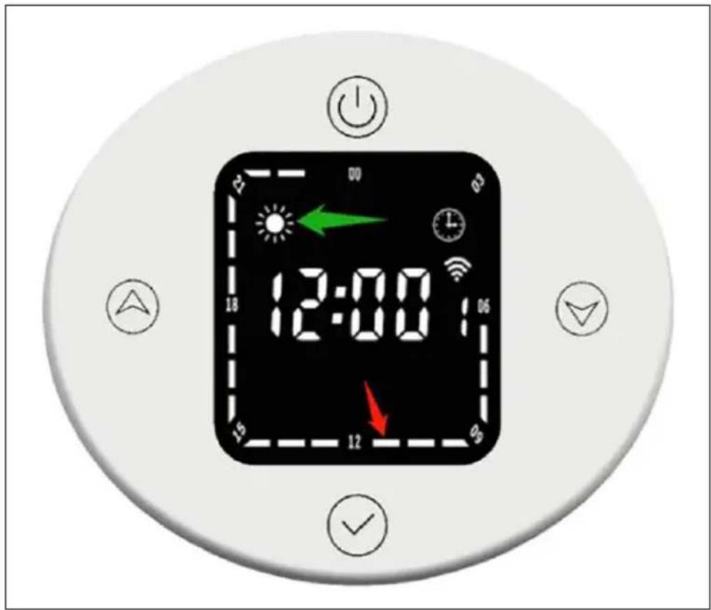
text_image
12:00 18 15 12 90 90 100 00 03 06 09 12 15 18 22 25 30 35 40 45 50 55 60 65 70 75 80 85 90 95 100The corresponding period of time (marked by the red arrow) represents the comfort mode. During this period, the time period display ■ vill illuminate for three seconds, then turn off for one second and the comfort mode icon will also illuminate (indicated by the green arrow).
Change operating mode in timer mode
For example, in timer mode, the current time is 12:30 and the thermostat runs in economy mode. If you briefly press the down button, the operating mode temporarily switches to comfort mode. If you briefly press the down button again, the operating mode temporarily switches to frost protection mode. When the next time span 13:00 is reached, the operating mode preset for this time is automatically restored.
Heating mode timer (turbo mode)
Briefly press the mode button to switch to heating mode timer. A temperature of 80^ C and a time span of 2 hours are preset.
- Setting the temperature
Briefy press the up down button to adjust the temperature in the range of 40-80°C, in 5°C increments. Pressing and holding the button speeds up the setting.
text_image
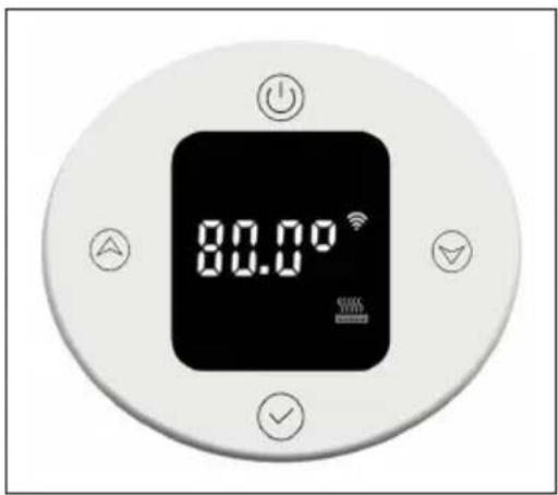
80.00° WIRE WIRE- Setting the timer
Press the mode button for 3 seconds to set the heating time. Briefly press the up or down button to set the time to 0-8 hours (0 means the timer setting will be cancelled, after 3 seconds the temperature will be displayed again). Pressing and holding the button speeds up the setting.
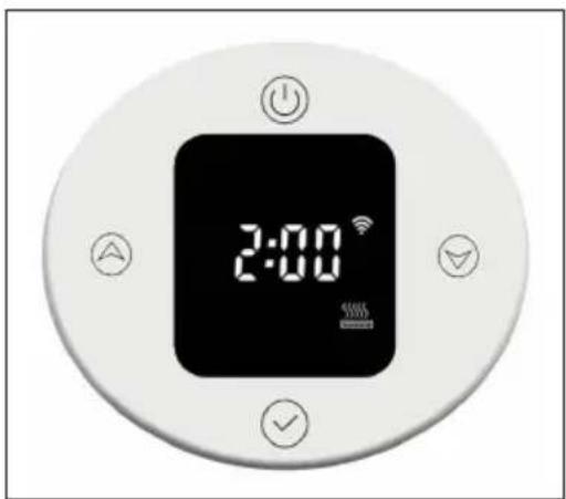
text_image
2:00When the timer expires, the device automatically returns to the previously set operating mode.
Child safety lock
Press the up and down buttons for 3 seconds to turn on the child lock. The display is locked and the child lock indicator lights up. All buttons except the on/off button are locked.
To turn off the child lock, press the up and down buttons for 3 seconds. The child lock indicator goes out.
text_image
12:00 14 16 18 20Frost protection
If the current temperature is below 7^ C when the device is switched off, the device will go into frost protection mode and heat at 7^ C. This avoids any risk of frost.
When the heating temperature of the device reaches 9^ C, the device will stop heating and continue heating only after the temperature drops.
Open window detection
In heating mode, if the ambient temperature suddenly drops 2 °C within 5 minutes, the unit will switch to open window detection mode. The device maintains a constant temperature of 7 °C in this mode and returns to normal heating mode after 60 minutes.
text_image
1.00°If the temperature drops again by 2 °C within 5 minutes, the device will switch to the constant temperature mode of 7 °C for another 60 minutes (refer to the "Internal Parameter Settings" section below for setting details).
DEVICE CONTROL VIA SMARTPHONE
If you integrate your Blumfeldt device into your home WLAN, you can operate it conveniently via the associated Blumfeldt app. The app not only allows you to control the device remotely via your smartphone, but also gives you access to recipes and further information.
Follow these steps to connect your smartphone to your Blumfeldt appliance:
- First download the Blumfeldt app by scanning the QR code with your smartphone (see below) or download it directly from the App Store or Google Play.
- Make sure that your smartphone is connected to the same WiFi network that your Blumfeldt device is to be connected to.
- Open the Blumfeldt app.
- Log in with your account. If you don't have an account yet, register in the Blumfeldt app.
- Follow the instructions in the app.
App download
Use the scan function of your mobile phone to scan the QR code and save the app on your smartphone.
Note: Further instructions on how to use the app and help on how to connect to your device are provided by the app when you open it for the first time.

text_image
iOS AndroidTroubleshooting connection problems
If your Blumfeldt device cannot be found in the WLAN, check the following:
- The device is not plugged in. Make sure that your unit is plugged into a power outlet.
- The unit is not in pairing mode. Make sure that the WiFi indicator (LED) on the control panel of the smart device is flashing as described in the "Reset WiFi settings" instruction of your smart device (instructions can usually be found under Device connection).
- The WiFi access point does not operate on 2.4 GHz. Make sure your access point is operating on the 2.4 GHz band and that you have your own SSID on the 2.4 GHz band. If you are unsure about the operating band of your access point, please contact your internet provider.
Important: Please note that if your WiFi router has a dual band - i.e. operates in both the 2.4 GHz and 5 GHz bands - you must separate the SSIDs for each band and use the 2.4 GHz SSID for the connection
-
Check the firewall settings of your WiFi network. The firewall setting of your WiFi network may not allow the Blumfeldt App to configure the WiFi settings on your smart device. Please ensure that you do not use a public WiFi network, e.g. airports, dormitories, companies, etc.
-
Different login data in the smartphone and in the app. Make sure that the WiFi login details entered in the Blumfeldt app match those to which your smartphone is connected.
If you have followed the above points and your smartphone still cannot connect to the app, please contact us by email for assistance: appsupport@go-bbg.com
INTERNAL PARAMETER SETTING
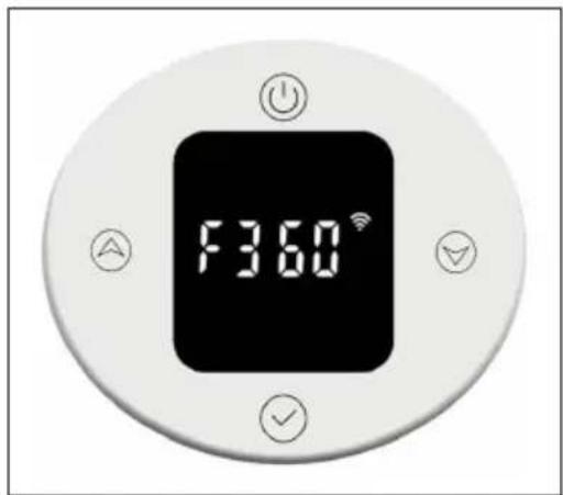
When the thermostat is off, press the on/off button for 10 seconds to enter the internal parameter setting. Briefly press the on/off button to switch between the settings: F0 temperature compensation > F1 open window detection function > F2 radiator temperature (comfort mode) > F3 radiator temperature (economy mode) > F4 WiFi settings > exit settings.
F0: Temperature compensation
The temperature compensation is 0 °C by default. Briefly press the up Ⓐ or down ⏚ button to set the temperature compensation. The temperature compensation can be adjusted in a range of 5 °C to -5 °C in 1 °C increments.
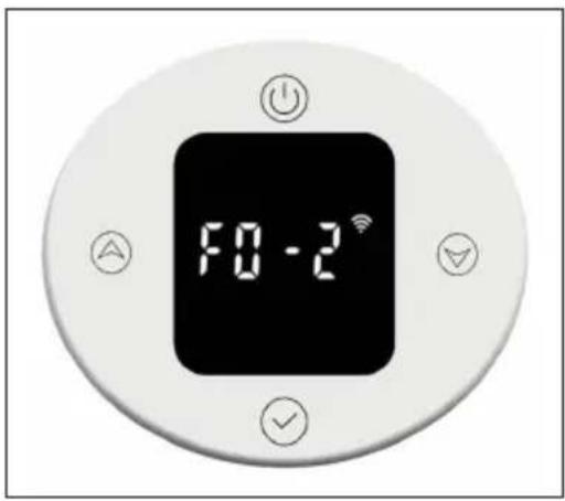
text_image
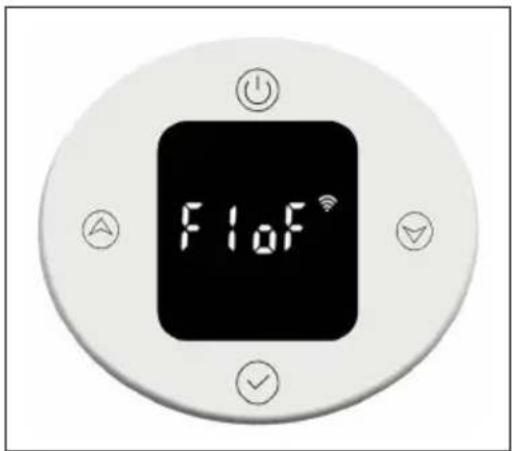
F0 - 2°F1: Open window detection function
Briefly press the up 📊 down button to enter open window detection settings. There are 3 options: oF > 30 > 60 > 90 (default is oF).
text_image
F1oFF2: Surface temperature of the radiator
Briefly press the up ▲ down ▼ button to set the temperature in the range of 40-80 °C (default is 80 °C).

text_image
F280°F3: Surface temperature of the radiator (economy mode)
Briefly press the up ▲ down ▼ button to set the temperature in the range of 40-60 °C (default is 60 °C).
text_image
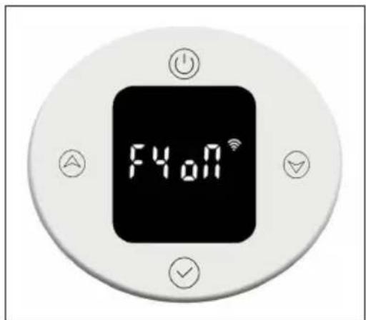
F3.60°F4: WiFi
Briefly press the up ▲ down button to enter WiFi settings. "on" means WiFi is on, "oF" means it is off (default is "on"). After successfully connecting to the network in the app, the network time will be synchronised automatically.
text_image
F4.0NRestoring the factory settings
When the device is on, press and hold the on/off button for 10 seconds, the system will automatically boot and restore the factory settings. This will be shown on the display for 3 seconds before the device turns off.
Pressing the on/off button restores the following factory settings: The temperature in comfort mode is set to 22 °C and in economy mode to 20 °C. The time is displayed as "00:00" and the day of the week as "1". Default settings are set for P1-P7. The heating mode timer is set to 80 °C for 2 hours heating. The temperature compensation is set to 0. The open window detection function will be turned off. The radiator surface temperature is set to "80" for comfort mode and "60" for economy mode. The WiFi will be switched on.
Error description
| Display Appearance Problem | |
| Err Interface not functional Temperature sensor | defective |
PRODUCT DATA SHEET
| Model identifier(s): | 10045588 | |||||
| Item Symbol Value Unit Item Unit | ||||||
| Heat output Type of heat input, for electric storage local space heaters only | ||||||
| Nominal heat output P | nom | 0.6 | kW manual heat charge control, with integrated thermostat | N/A | ||
| Minimum heat output (indicative) | Pmin | 0.6 | kW manual heat charge control with room and/or outdoor temperature feedback | N/A | ||
| Maximum continuous heat output | Pmax,c | 0.6 | kW electronic heat charge control with room and/or outdoor temperature feedback | N/A | ||
| Auxiliary electricity consumption fan assisted heat output N/A | ||||||
| At nominal heat output (fan motor) | elmax | N/A kW | Type of heat output/room temperature control | |||
| At minimum heat output (fan motor) | elmin | N/A kW | single stage | heat output and no room temperature control | no | |
| In standby mode el | SB | 0.5 | W | Two or more manual stages, no room temperature control | no | |
| with mechanic thermostat room temperature control | no | |||||
| with electronic room temperature control | no | |||||
| electronic room temperature control plus day timer | no | |||||
| electronic room temperature control plus week timer | yes | |||||
| Other control options (multiple selections possible) | ||||||
| room temperature control, with presence detection | no | |||||
| room temperature control, with open window detection | yes | |||||
| with distance control option | no | |||||
| with adaptive start control | no | |||||
| with working time limitation | no | |||||
| with black bulb sensor | no | |||||
| Contact details | Chal-Tec GmbH, Wallstraße 16, 10179, Berlin, Germany | |||||
| Model identifier(s): | 10045589 | |||||
| Item | Symbol | Value Unit | tem Unit | |||
| Heat output Type of heat input, for electric storage local space heaters only | ||||||
| Nominal heat output P | nom | 0.8 | kW manual heat charge control, with integrated thermostat | N/A | ||
| Minimum heat output (indicative) | Pmin | 0.8 | kW manual heat charge control with room and/or outdoor temperature feedback | N/A | ||
| Maximum continuous heat output | Pmax,c | 0.8 | kW electronic heat charge control with room and/or outdoor temperature feedback | N/A | ||
| Auxiliary electricity consumption fan assisted heat output N/A | ||||||
| At nominal heat output (fan motor) | elmax | N/A kW | Type of heat output/room temperature control | |||
| At minimum heat output (fan motor) | elmin | N/A kW | single stage heat output and no room temperature control | no | ||
| In standby mode el | SB | 0.5 W | Two or more manual stages, no room temperature control | no | ||
| with mechanic thermostat room temperature control | no | |||||
| with electronic room temperature control no | ||||||
| electronic room temperature control plus day timer | no | |||||
| electronic room temperature control plus week timer | yes | |||||
| Other control options (multiple selections possible) | ||||||
| room temperature control, with presence detection | no | |||||
| room temperature control, with open window detection | yes | |||||
| with distance control option | no | |||||
| with adaptive start control | no | |||||
| with working time limitation | no | |||||
| with black bulb sensor | no | |||||
| Contact details | Chal-Tec GmbH, Wallstraße 16, 10179, Berlin, Germany | |||||
DISPOSAL CONSIDERATIONS

natural_image
Symbol of a trash bin crossed with a diagonal line, no text or numbers presentIf there is a legal regulation for the disposal of electrical and electronic devices in your country, this symbol on the product or on the packaging indicates that this product must not be disposed of with household waste. Instead, it must be taken to a collection point for the recycling of electrical and electronic equipment. By disposing of it in accordance with the rules, you are protecting the environment and the health of your fellow human beings from negative consequences. For information about the recycling and disposal of this product, please contact your local authority or your household waste disposal service.
This product contains batteries. If there is a legal regulation for the disposal of batteries in your country, the batteries must not be disposed of with household waste. Find out about local regulations for disposing of batteries. By disposing of them in accordance with the rules, you are protecting the environment and the health of your fellow human beings from negative consequences.
DECLARATION OF CONFORMITY

text_image
CE UK CAManufacturer:
Chal-Tec GmbH, Wallstrasse 16, 10179 Berlin, Germany.
Importer for Great Britain:
Berlin Brands Group UK Limited PO Box 42
272 Kensington High Street
London, W8 6ND
United Kingdom
Hereby, Chal-Tec GmbH declares that the radio equipment type Fairmont Smart is in compliance with Directive 2014/53/EU. The full text of the EU declaration of conformity is available at the following internet address: use.berlin/10045588
For Great Britain: Hereby, Chal-Tec GmbH declares that the radio equipment type Fairmont Smart is in compliance with the relevant statutory requirements. The full text of the declaration of conformity is available at the following internet address: use.berlin/10045588
Cher client, chère cliente,
text_image
QR code image containing encoded data, no visible human-readable textSOMMAIRE
text_image
Diagram illustrating a drill bit setup with labeled components and directional arrows, including a magnified inset showing the drill bit path.flowchart
graph TD
    A["Left panel: Lateral structure"] --> B["Top view of mechanical assembly"]
    B --> C["Downward arrow to right panel"]
    C --> D["Bottom view of mechanical assembly"]
    style A fill:#f9f,stroke:#333
    style B fill:#ccf,stroke:#333
    style C fill:#cfc,stroke:#333
    style D fill:#fcc,stroke:#333
natural_image
Black square icon with white icons for Wi-Fi, a clock, and signal waves (no text or symbols)text_image
80.00° 500VFICHE DE DONNÉES PRODUIT
natural_image
Symbol of a trash bin crossed with a diagonal line, no text or labels presentDÉCLARATION DE CONFORMITÉ

text_image
CE UK CAFabricant :
Chal-Tec GmbH, Wallstraße 16, 10179 Berlin, Allemagne.
Berlin Brands Group UK Ltd PO Box 42 272 Kensington High Street London, W8 6ND United Kingdom
flowchart
graph TD
    A["Tool with 2000s"] --> B["Adder"]
    B --> C["Adder to 2000s"]
    C --> D["Adder to 2000s"]
    D --> E["Adder to 2000s"]
    E --> F["Adder to 2000s"]
    F --> G["Adder to 2000s"]
    G --> H["Adder to 2000s"]
    H --> I["Adder to 2000s"]
    I --> J["Adder to 2000s"]
    J --> K["Adder to 2000s"]
    K --> L["Adder to 2000s"]
    L --> M["Adder to 2000s"]
    M --> N["Adder to 2000s"]
    N --> O["Adder to 2000s"]
    O --> P["Adder to 2000s"]
    P --> Q["Adder to 2000s"]
    Q --> R["Adder to 2000s"]
    R --> S["Adder to 2000s"]
    S --> T["Adder to 2000s"]
    T --> U["Adder to 2000s"]
    U --> V["Adder to 2000s"]
    V --> W["Adder to 2000s"]
    W --> X["Adder to 2000s"]
    X --> Y["Adder to 2000s"]
    Y --> Z["Adder to 2000s"]
flowchart
graph TD
    A["Left panel: Lateral structure"] --> B["Top view of mechanical assembly"]
    B --> C["Downward arrow to right, indicating assembly direction"]
    C --> D["Bottom view of mechanical assembly with screw and shaft"]
text_image
1.00° 1.00°natural_image
Black rounded square icon with white icons for time, Wi-Fi, and alarm (no text or symbols)natural_image
Symbol of a trash bin crossed with a diagonal line, no text or labels presentBerlin Brands Group UK Limited PO Box 42
272 Kensington High Street
London, W8 6ND
United Kingdom
text_image
QR code image containing encoded data, no visible human-readable textÍNDICE
text_image
Diagram illustrating a drill bit setup with labeled components and directional arrows, including a magnified inset showing the drill bit path.- Perfore la pared e inserte los tacos.
flowchart
graph TD
    A["Left panel: L-shaped structure"] --> B["Top view of mechanical assembly"]
    B --> C["Downward arrow indicating assembly direction"]
    C --> D["Bottom view of mechanical assembly with screw and nut"]
natural_image
Black rounded square icon with white icons for time, Wi-Fi, and alarm (no text or symbols)text_image
QR code with a green logo in the center, likely linking to a digital service or website.
text_image
QR code with a green logo in the center, likely linking to a digital service or website.natural_image
Symbol of a trash bin crossed with a diagonal line, no text or labels presentBerlin Brands Group UK Limited PO Box 42
272 Kensington High Street
London, W8 6ND
Reino Unido