
PTH - Hand tool Panduit - Free user manual and instructions
Find the device manual for free PTH Panduit in PDF.


| Product Type | Pneumatic cable tie installation tool |
| Brand | Panduit |
| Model | PTH |
| Application | Installation of standard (S), heavy standard (HS), light-heavy (LH), and heavy (H) cable ties |
| Power Source | Compressed air (max pressure 6.9 bar / 100 PSIG) |
| Recommended Pressure | 5.2 bar (75 PSIG) |
| Dimensions (L x H) | 284 mm x 173 mm (approximate) |
| Weight | 907 g (32 oz) |
| Tie Capacity (Width) | S: 4.8 mm; HS: 6.4 mm; LH and H: 7.6 mm; H: 8.9 mm |
| Tension Adjustment | Scale 0-8 with matching tie types |
| Cutting Function | Automatic cut-off of excess tie length |
| Blade Life | 100,000 cycles (normal conditions) |
| Sound Level | 73 dB (per ISO 15744) |
| Vibration Level | 1.8 m/s² (per ISO 20643) |
| Air Consumption | 0.157 scfm @ 75 PSIG (0.074 l/s ANR @ 5.2 bar) at 30 cycles/min |
| Recommended Maintenance | Daily check of blade/gripper area, clean residue |
| Replacement Parts | Blade (KPTHBLD), protection cover (KPTSTL), blade guard (WH25007C01) |
| Accessories | Filter regulator with gauge MK-06, air hose PPH10G |
| Safety | Safety glasses, hearing protection, do not use on live circuits, disconnect air before maintenance |
| Operating Environment | Do not use in explosive atmosphere |
Frequently Asked Questions - PTH Panduit
User questions about PTH Panduit
0 question about this device. Answer the ones you know or ask your own.
Ask a new question about this device
Download the instructions for your Hand tool in PDF format for free! Find your manual PTH - Panduit and take your electronic device back in hand. On this page are published all the documents necessary for the use of your device. PTH by Panduit.
USER MANUAL PTH Panduit
natural_image
Icon of a person reading a document inside a black circle (no text or symbols)WARNING
- TO REDUCE THE RISK OF INJURY, USER MUST READ AND UNDERSTAND THE SAFETY INSTRUCTIONS BEFORE INSTALLING, OPERATING, REPAIRING, MAINTAINING OR CHANGING ACCESSORIES ON THIS TOOL. FAILURE TO DO SO CAN RESULT IN SERIOUS BODILY INJURY.
• RETAIN THIS MANUAL FOR FUTURE REFERENCE
U.S.A. Email:
U.S.A. Technical Support
Panduit Electrical Headquarters
16530 W. 163rd Street, Lockport, IL 60441
Tel: 1-800-777-3300
Panduit Europe • EMEA Service Center
Almelo, Netherlands
Tel: +31 546 580 452
Fax: +31 546 580 441
Guadalajara, Jalisco, Mexico
Tel: 52 (333) 666 2501
Fax: 52 (333) 666 2510
The PTH Tool installs Panduit Standard (S), Heavy-Standard (HS), Light-Heavy (LH) and Heavy (H) cross section cable ties. The tool pneumatically tensions the cable tie to a tool-controlled tension and cuts off the tip.
TOOL SPECIFICATIONS
Weight: 32 oz. (907 gr.)
Dimensions*: 11.18" (284mm) Long X 6.81" (173mm) High
* Dimensions in parentheses are metric; all dimensions are approximate, and for reference only.

GENERAL SAFETY PRACTICES
- For multiple hazards, read and understand the safety instructions before installing, operating, repairing, maintaining, changing accessories on, or working near the pneumatic tool. Failure to do so can result in serious bodily injury.
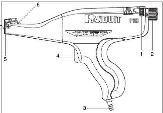
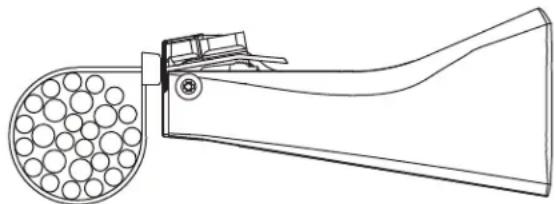
PTH Pneumatic Tool
- Tension Indicator 4. Trigger
- Selector Knob 5. Nose
-
Quick Disconnect Fitting 6. Gripper
-
Only qualified and trained operators should install, adjust or use the pneumatic tool
- DO NOT modify this pneumatic tool. Modifications can reduce the effectiveness of safety measures and increase the risks to the operator
- DO NOT discard the safety instructions; give them to the operator
• DO NOT use the pneumatic tool if it has been damaged - Tools shall be inspected periodically to verify that the ratings and markings required by this part of ISO 11148 are legibly marked on the tool. The employer/user shall contact the manufacturer to obtain replacement marking labels when necessary
• DO NOT use tool for purposes not intended. Unexpected tool movement or breakage of tool may cause injuries to hand
• Unsuitable postures may not allow counteracting of normal or unexpected movement of the tool
 | For multiple hazards, read and understand the safety instructions before installing, operating, repairing, maintaining, changing accessories on, or working near the pneumatic tool. |
 | Safety glasses must be worn at all times by all persons within ten (10) feet of any part of the system.CAUTION: Be aware of the ejection of cable tie scrap from tool. |
 | DO NOT use tool on live electrical sources. |
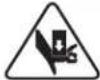 | CAUTION! Pinch Point. Keep hands and fingers clear. |
 | DO NOT use tool in an explosive atmosphere. |
 | Ear protection should be worn when operating the tool. |
Projectile Hazards:
- Disconnect the pneumatic tool from the energy source when changing inserted tools or accessories
- Always wear impact-resistant eye protection during operation of the tool. The grade of protection required should be assessed for each use
- Ensure that the workpiece is securely fixed
- Be aware that working on brittle material can cause harmful splinters
Operating Hazards:
- Use of the tool may expose the operator's hands to hazards, including impacts, cuts, abrasions and heat; wear suitable gloves to protect hands
- Operators and maintenance personnel shall be physically able to handle the bulk, weight and power of the tool
- Hold the tool correctly; re ready to counteract normal or sudden movements and have both hands available
- Maintain a balanced body position and secure footing; avoid awkward or off-balanced postures, change posture during extended tasks; this can help avoid discomfort and fatigue
- Use only lubricants recommended by the manufacturer
- Be aware of the risk of a whipping compressed air hose
Repetitive Motion Hazards:
- When using a pneumatic tool to perform work-related activities, the operator can experience discomfort in the hands, arms shoulders, neck or other parts of the body
- While using a pneumatic tool, the operator should adopt a comfortable posture while maintaining secure footing and avoiding awkward or off-balance postures. The operator should change posture during extended tasks; this can help avoid discomfort and fatigue
- If the operator experiences symptoms such as persistent or recurring discomfort, pain, throbbing, aching, tingling, numbness, burning sensations or stiffness; these warning signs should not be ignored. The operator should tell the employer and consult a qualified health professional
Workplace Hazards:
- Slips, trips and falls are major causes of workplace injury. Be aware of slippery surfaces caused by use of the tool and also of trip hazards caused by the air line or hydraulic hose
• Proceed with care in unfamiliar surroundings. There can be hidden hazards, such as electricity or other utility lines - Ensure that there are no electrical cables, gas pipes, etc., which can cause a hazard if damaged by use of the tool
Additional Safety Instructions:
- Air under pressure can cause severe injury. Always shut off air supply, drain hose of air pressure and disconnect tool from air supply when not in use, before changing accessories or when making repairs
- Whipping hoses can cause severe injury. Always check for damaged or loose hoses and fittings
- DO NOT exceed the maximum air pressure stated on the tool
- Never carry a pneumatic tool by the hose
Periodic Maintenance:
Make sure tool is clean before each use.

NOTE: In the interest of higher quality and value, Panduit products are continually being improved and updated. Consequently, pictures may vary from the enclosed product.
SETUP
- Connect 1/8" NPT male fitting of PPH10 Air Supply Hose to 1/8" NPT female port of PL289N1 Filter/Regulator.
- Connect 1/8" female quick disconnect socket end of Air Supply Hose to 1/8" male quick disconnect fitting at end of PTH Tool.
- Connect filter/regulator to main NON-LUBRICATED air supply and set regulator at 75 PSIG (5.2 bar). See Air Supply specifications on next page.
OPERATION
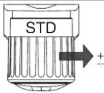
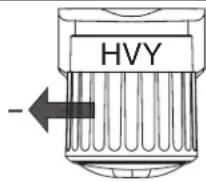
- Reading the tension knob from the top of the tool, rotate the knob to select the cross section of cable ties to be installed.
STD – S: Approx. .190" (4.8mm) wide cable ties HVY – HS: Approx. .250" (6.4mm) wide cable ties LH: Approx. .300" (7.6mm) wide cable ties H: Approx. .300" (7.6mm) wide cable ties Approx. .350" (8.9mm) wide cable ties
If necessary, further adjust tension per Tension Adjustment instructions below.
- Loop cable tie around bundle and insert the tip through the head. Pull the tie up snug on the bundle by hand.
- Insert the strap of the cable tie into the side of the tool. With the nose of the tool flush to the cable tie head, squeeze the trigger to tighten the cable tie. Typically, only one depression of trigger is necessary for cable tie cut-off.
natural_image
Technical line drawing of a mechanical device with circular components and a handle (no text or symbols)TENSION ADJUSTMENT
There is a tension indicator on the top of the tool. The tens setting can be changed by turning the fine adjustment knob:
0-4 for Standard
4-6 for Heavy-Standard
5-6 for Light-Heavy
5-8 for Heavy
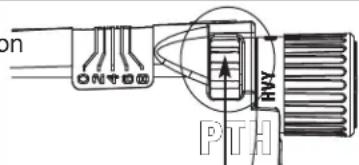
Fine Adjustment Knob
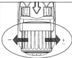
DAILY TOOL INSPECTION
- Visually inspect nose area for foreign matter and cable tie scrap. Keep this area clear of foreign matter.
- Visually inspect applied cable ties for correct tension and cut-off to verify the working condition of the blade and gripper.
| PTH Replacement Kits and Accessories Available • Contact Panduit for more information | |
| KPTHBLD | Blade Replacement Kit - For replacement of a worn blade |
| KPTSTL | Tool Tension Locking Kit - May be installed to prevent adjustment of the tension knob |
| PHCAQ | Adapter Fitting for Hose (PPH10) - 1/4" Male Quick Disconnect (to regulator). |
| PHCAT | Adapter Fitting for Hose (PPH10) - 1/4" NPT Male Connection (to regulator). |
| WH25007C01 | Blade Guard Housing - For replacement of a worn blade guard |
TECHNICAL SPECIFICATIONS - Air Supply
| ITEM | DESCRIPTION |
| Recommended regulated air pressure supplied to tool (pressures other than recommended may result in unsatisfactory operation): | Regulator settings: 75 PSIG (5,2 bar) with a max. 10 PSI (0,7 bar) drop.MAXIMUM 100 PSIG (6,9 bar). |
| Air consumption at 30 cycles per minute: | .157 scfm @ 75 PSIG (0,074 l/sec ANR @ 5,2 bar) |
| Line pressure supplied to regulator: | Minimum 70 PSIG (4,8 bar), Maximum 100 PSIG (6,9 bar) |
| Filter/regulator requirements: | 5 micron maximum element rating, 5 PSI (0,3 bar) maximum pressure drop @ 70 PSIG (4,8 bar) inlet pressure and 12 cfm (5,7 l/sec) flow minimum. |
| Lubrication for air supply: | Air line lubricators are NOT to be used. |
| Filter / Regulator 0.5 micron element, regulated range 3-100 psig., features 1/8" NPT female output port (to Hose, PPH10) and 1/4" male quick disconnect to source air line. Use with PTS and PTH | Recommended source: Panduit Part Number PL289N1EU Panduit Part Number:MK-06 |
| Recommended main air supply hose (10 ft.), (supplied by user) from filter/regulator to tool (supplied by user); includes a 1/8" NPT male connector (to regulator) and a 1/8" quick disconnect socket (to tool): | Recommended source: Panduit Part Number PPH10EU Panduit Part Number:PPH10G |
OTHER SPECIFICATIONS
| DESCRIPTION VALUE | |
| Life cycle of the blade under normal operating conditions 100,000 cycles | |
| Sound Level:Measured sound level per ISO 15744 | 73 dB |
| Vibration Level:Measured vibration level per ISO 20643 | 1.8 m/s^2 |
TROUBLESHOOTING
| SYMPTOM POSSIBLE CAUSE CORRECTIVE ACTION | ||
| Tool will not operate. | No air pressure at tool. Verify that air supply is “on”, and that connections are good,to be sure that tool is receiving air. | |
| Tool will not cut off cable tie. | A. Air pressure too low.B. Tool has reached end of stroke.C. Tool cutter blade is broken or dull. | A. Check air supply regulator for proper adjustment.Increase air pressure if necessary.B. Release trigger and squeeze again.C. Replace blade using KPTHBLD Blade Replacement Kit. |
| Gripper will not return to forward position. | Material wedged in nose area. • Depress and hold the trigger to actuate the tool.• The gripper should remain in it's back position.• Once actuated, carefully remove the material from the nose area.• Once your hand is clear from the nose and gripper, you may safely release trigger. | |
| Cable tie is slipping in gripper. | Gripper is worn or damaged. Contact Panduit | |
| Cable tie is too loose on bundle. | A. Tool tension setting is too low.B. Operator holding tool at angle to bundle.C. Tool is held away from bundle by previously installed cable tie, harness support, or other object on bundle.D. Tool is pulled on as tie is being tensioned. | A. Check tension knob for proper setting for specific cable tie being applied (See Tension Adjustment).B. Hold tool perpendicular to bundle in both directions.C. Do not install cable ties too close to other cable ties, harness supports or other objects on bundle.D. Allow tool to seek its own position as the tie is being tensioned. |
| Cable tie is too tight on bundle. | Tool tension setting is too high. Check tension knob for proper setting for specific cable tie being applied (See Tension Adjustment). | |
| Cable ties will not stay on bundle. | Wire bundle exceeds maximum diameter for specific cable tie being applied. | Operator should dress the wires to result in a more compact bundle. |
| Air leaks from tool. A. | Loose or bad fittings.B. Worn or bad hoses.C. Worn or bad air cylinder assembly. | Contact Panduit |
natural_image
Line drawing of a mechanical device with circular components and a handle (no text or symbols)FEINEINSTELLUNG
natural_image
Technical diagram of a mechanical component with internal channels and directional arrows (no text or symbols)TÄGLICHE WERKZEUGKONTROLLE
natural_image
Technical line drawing of a mechanical device with circular components and a handle (no text or symbols)AJUSTAGE FIN
natural_image
Diagram of a mechanical component with directional arrows and polarity signs (no text or symbols)CONTROLE JOURNALIER DE L'OUTIL
Attrezzo pneumatica PTH
natural_image
Line drawing of a mechanical device with circular components and a handle (no text or symbols)natural_image
Line drawing of a mechanical device with circular components and a handle (no text or symbols)AJUSTE DE PRECISION
natural_image
Technical diagram of a mechanical component with directional arrows and polarity indicators (no text or symbols)


- WARNING
- TOOL SPECIFICATIONS
- GENERAL SAFETY PRACTICES
- Projectile Hazards:
- Operating Hazards:
- Repetitive Motion Hazards:
- Workplace Hazards:
- Additional Safety Instructions:
- Periodic Maintenance:
- SETUP
- OPERATION
- TENSION ADJUSTMENT
- DAILY TOOL INSPECTION
- FEINEINSTELLUNG
- TÄGLICHE WERKZEUGKONTROLLE
- AJUSTAGE FIN
- CONTROLE JOURNALIER DE L'OUTIL
- AJUSTE DE PRECISION
Brand : Panduit
Model : PTH
Category : Hand tool