
EWADC15C-PS - Air Conditioning DAIKIN - Free user manual and instructions
Find the device manual for free EWADC15C-PS DAIKIN in PDF.

| Brand | Daikin |
| Model | EWADC15C-PS |
| Product Type | Air-cooled chiller (chilled water unit) |
| Use | Industrial/commercial air conditioning - cooling of water or water-glycol mixture |
| Refrigerant | R134a (GWP = 1430) |
| Compressor | Screw type |
| Condenser | Air-cooled, finned coils |
| Evaporator | Plate or tubular heat exchanger (not specified) |
| Anti-freeze protection | Electric heater with thermostat (up to -25°C) |
| Power supply | Three-phase (voltage per nameplate) |
| Ambient temperature limits | Storage: -20°C to 57°C; Operation: according to Figure 2 in the manual |
| Nominal water flow | Between 50% and 140% of nominal flow |
| Sound pressure | Level according to commercial documentation (not specified in manual) |
| Sound level | Sound emission does not require special protection under normal use |
| Safety | Safety valves, emergency stop, main switch, flow switch |
| Installation | Outdoor, on concrete slab or beams, minimum ventilation distances |
| Maintenance | Periodic cleaning of coils, leak check, oil analysis |
| Warranty | 12 months after commissioning or 18 months after delivery |
| Country of origin | Not specified (manufacturer Daikin) |
| Weight | According to model (not provided in manual) |
| Dimensions | According to model (not provided in manual) |
Frequently Asked Questions - EWADC15C-PS DAIKIN
User questions about EWADC15C-PS DAIKIN
0 question about this device. Answer the ones you know or ask your own.
Ask a new question about this device
Download the instructions for your Air Conditioning in PDF format for free! Find your manual EWADC15C-PS - DAIKIN and take your electronic device back in hand. On this page are published all the documents necessary for the use of your device. EWADC15C-PS by DAIKIN.
USER MANUAL EWADC15C-PS DAIKIN
Installation, Operation and Maintenance Manu Installation, Operation and Maintenance Manual
D-EIMAC00608-16EU
Air cooled screw chillers
EWAD~C-SS EWAD~C-XS EWAD~C-PS
EWAD~C-XL EWAD~C-SL EWAD~C-PL
EWAD~C-SR EWAD~C-XR EWAD~C-PR
Refrigerant: R-134a
Cooling capacity from 619 to 2008 kW

| English | 9 |
| Deutsch | 20 |
| Français | 30 |
| Nederlands | 42 |
| Espanol | 53 |
| Italiano | 64 |
| Ελληνικά | 75 |
| Português | 87 |
| Yüccský | 98 |
| Swedish | 109 |
| Norsk | 120 |
| Finnish (Suomi) | 131 |
| Polski | 142 |
| Čech | 153 |
| Hrvat | 164 |
| Magyar | 175 |
| Român | 186 |
| Slovenski | 198 |
| Бълар检n | 209 |
| Slovenský | 220 |
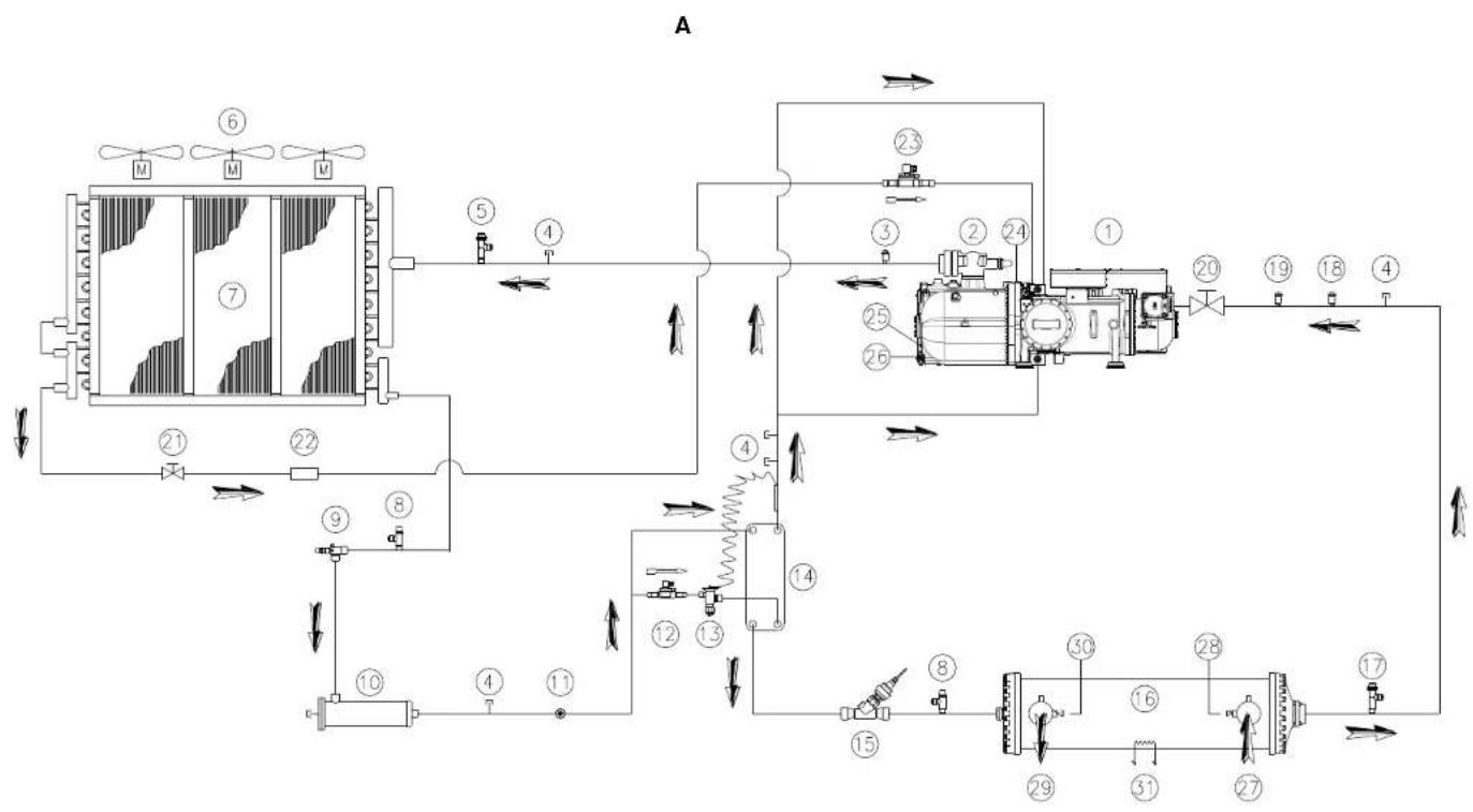
A - Typical refrigerant circuit - Water inlet and outlet are indicative. Please refer to the machine dimensional diagrams for exact water connections.
A - Typischer Kuhlkreislauf - Wasser-Ein- und Ausgang sind unverbindlich.itte beziehen Sie sich auf die Gerateabmessungs-Diagramme fur genaue Wasseranschlusse.
A - Circuit de refroidissement typique - L'arrivee et la sortie d'eau sont reportes a titre indicatif. Veuillez you reporter aux schemas dimensionnels de la machine pour identiter les raccordements exacts de I'eau.
A - Typisch koelmiddelcircuit - Wateriataat en -uitaat zijn indicatief. Zie de dimensionele diagrams van de machine voor de juiste wateraansluitingen.
A - Circuito de refrigeracion típico - la entrada y la calidad de agua son indicativas. Consulte los diagramas de dimensiones de laquina para poder las conexiones de agua exactas.
A - Tipico circuito refrigerante - L'ingresso e l'uscita dell'acqua sono indicativi. Consultare i diagrammi dimensionali delle machine per i collegamenti伊拉ici esatti.
A - TUTKIO KUKLWJU YUKTKIOU JEAOU-H TAPOXI EIOOBOU KAI EIOBOV VPOU EIAV ESEIKIKN. AvatpE TE Oa diaypapmaia diaotaeuw Tou nXavHnatoC iaTc AkiPeic auvSeaeic vepo.
A-Circuito típico refrigerante- Entrada e saida de agua sao indicativas.Consultar os diagramas dimensionais da macquina para as conexoes certas da agua.
A-CTaHaprBTHo KHTpyAaHepBHTa HApNcHbIy HmNcyKbHbY BoDopOBoBHe bOeBpTcN oK3aHbI ynnbI pynmpEpa. IJnaOpeneHn npKaIOuOeHn BODopOBtChcEytayUHbTaBbTaDaHbeRabapnTHbX cHepTeckx OobpyOaBHn
A - Typisk kylkrets - Vattenledningens inlopp och utlopp ar ungefärliga. Se maskinens dimensionsdiagram for exakta vattenansluttingar.
A - Typisk kjolemiediekrets - vanninntak og -uttak er kun antydninger. Se maskinens maltegnninger for noyaktige vanntilkoblinger
A-Typpillinen jaahdytyspiiri - Vedentulo- ja poistoaukot ovat viitteelliset. Katso tarkat vesilitiannat koneen mittakaavioista.
A - Typow obw odcznna chlodniczego - wskazane.), odpwyu i odplywu wody ma ekakter poglady. Dokladne.), wodnej wskazano na rysunkh wymiariowanych.
A-Typicky chladici obvod - Privod a odrov dvoudy jsou Jednoznaene. Pfnny postup priopojeni vody viz nakresy stroje.
A - Tipčni rashladni krug - ulaz i izlaz za vodu su samo za indikaciju. Pogledajte mjerne skice stroja akоŽelte točan pošćaj pričljučaka za vodu.
A - Tipikus húto áramkor - A vizbeomlo-és kiomlonyllas jelezesszeru. A pontos összekottetesekert lásd a berendezés szerkezeti rajzát.
A-Circuit de racire tipic-Intrarea siesirea pursuant apau rol indicativ.Va rugam sa consultat diagramele masini cu dimensiunile penta conexiunile exacte la ap
A - Tipicen tokokrog hladilnegaa sredsta - vodni dovod in odvod sta indikativna. Za natanene vodne povezave glejte diagrame dimenzij naprave.
A-TinuHnOxIaIeTIbepRHa-BoHNITeBXOIOBcN3XoDcyaK3aTeHH. MoJI, Hapabete CnpBaKc cIaNRpaMNTe Cp3MePHTe Ha MaINIHATA 3a TOHTHE BoHN Bp3KN
A - Typicky obvod chladiacej zmesi. Vstup a vystup vody su indikativne.. Presná poloha pripojakov dje yvznačena na Rozmerovych vykresoch zariadenia.
D-EIMAC00608-16EU -2/234
D-EIMAC00608-16EU-3/234
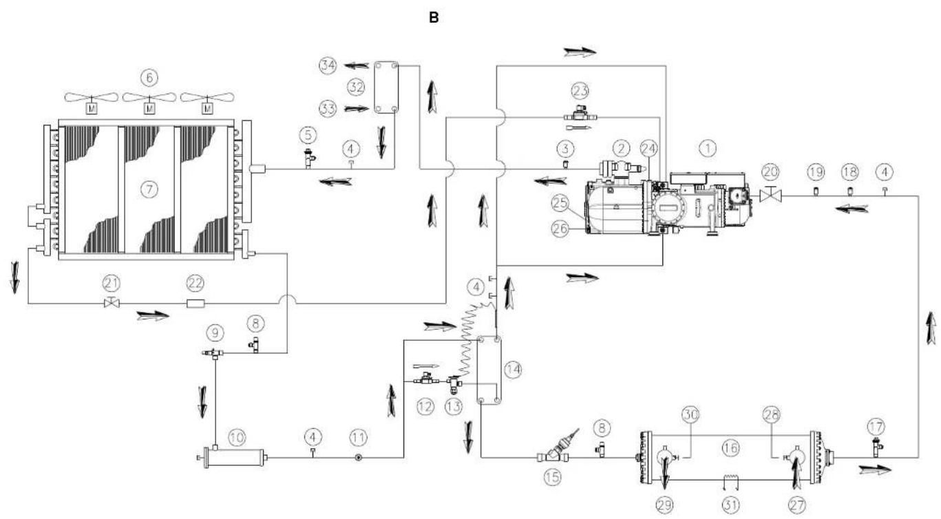
B - Typical refrigerant circuit with heat recovery - Water inlet and outlet are indicative. Please refer to the machine dimensional diagrams for exact water connections.
B - Typischer Kuhlkreislauf mit Wärmerückgewinnung - Wasser-Ein- und Ausgang sind unverbindlich.itte beziehen sie sich auf die Gerateabmessungs-Diagramme fur genaue Wasseranschluse
B - Circuit de refroidissement typique avec récapuration de chaleur - L'arrivée et la sortie d'eau sont reportés à titre indicatif. Veuillez vous reporter aux schémas dimensionnels de la machine pour identifier les raccordements exacts de l'eau.
B - Typisch koelmiddelcircuit - Wateripltaat en -uitlaut aan indicatief. Zie de dimensionele diagrams van de machine voor de juiste wateraansluitingen.
B - Cine t i a i i i i i i i i i i i i i i i i i i i i i i i i i i i i
Idraulic esatti.
B-TUTIKO KUKU OJAKTOKU MEOU OEVAKNTN OEPPTNAC-H TAPOXI EIOAOKAI EIOAO VEPOU EIVAI EVDEIKTKAVATPEGTE OTA DIAYPAPMATA DIAOTAeWTO UXANVAMOTCVAI TIC AKIPJIKAOWU VSEOEIEVEPO
B - Circuito típico refrigerante com recuperação de calor -- Entrada e��a de agua são indicativas. Consultar os diagramas dimensionais da其间ina para as conexoes certas da agua.
B-CTaHApTnKoTHyPknAeHnTa c pernyepaHnn Tnnna-BynCkHbNue bOaONpOBoDhne OTbEPcTn NOKaAHnPiuIbn pynmepa. IAn onpeJeHnA HApamETpoNkIOHEn BODAPoDHO CneJeTy uHTbBaTb DaheBraapOHNtXe qpeTeXe6OpBOHaHn
B -Typiskykelrets medvarteatverinening - Vattenledingnengins inlopp och utloppar er ungefargla. Se maskinen dimensionsdiagram for exakta vattenansluttinger. B -Typiskjolemediekrets medvarmejgrenvinening - Vannintank og -uttak er kun antydngner. Se maskinen maltagneiger for noyaktige vanvollklogger.
B-Typpillinen jaahdytyspiir lammon talleenototta - Vedentulo- ja poistoaukot ovat vitteelliset. Katso tarkat vesilitannat koneen mittakaavioista.
B - Typow obwod czynnka chlondniczego z odzyskiem ciepla. Wskazane.), doplywu i odplywu wody ma charakter poglady. Dokladne.), podlaczen instalacji wodnej wskazano na rysunkach wymiarowych.
B - Typciky chladici obvod s rekuperaci teplat - Privod a odvod vody jsou prukazne. Presne zapojeni viz nakresy stroje.
B - Tipčni rashladni krug s povratom topline - ulaz i izlaz za vodu su samo za indikaciju. Pogledajte mjme skice stroja ak o Želite točan pošžaj pričljučaka za vodu.
B - Tipikus húto áramkor hóviassanyerö berendezéssel - A vizbeomó-és kiomiñnylas jelésszerü. A起点 összekötteteşektér lásd a berendezes szerkezeti rajzt. B-Circuit de ràcire tipic cu recuperare de caldurá. Intrarea si iesirea pentru apa au rol indicativ. Vă rugam sa consultati diagrame masinii cu dimensiunile pentru conexiunile exacte la apà.
B - Tipicen tokokrog hladilnegra sredstva z obnavlanjem toploe - vodni dovod in odvod sta indikativna. Za natancne vodne povezave gleje diagrame dimenzij naprave.
B-TMnHvOxNAdTeHNb BeprC b3cTahOBBaHe Ha ToPnIHATA -BoDHnBe BXoDBe HxOOna Ca yka3AteTNH. MoJI, HapABete cnpabKa c dmApamite c p3mePHTe HA MauHHa 3a ToOHnB BoDHnBPb3Kn.
B - Typicky obvod chadiacej zmesi regeneraciou tepla. Vstup a vystup vody su indikativne. Presna poloha pripojok vody je vyznacena na rozmerovych vykresoch zariadenia.
D-EIMAC00608-16EU-5/234
| English | Deutsch | Français | Nederlands | Espanol | Italien | |
| 1 | Compressor | Vendhior | Compresseur | Compressor | Compressor | Compressor |
| 2 | Discharge shut off valve | Vorlaubaspermantil | Robnei de refoulement | Persolafuter | Grö. de saldo | Rubinetto di mandato |
| 3 | High-pressure transducer | Hochinsenkssensor | Transducertueur haute pression | Oerzotner hoge druk | Transducer du alte presinie | Transducertoe ala pressione |
| 4 | Servo port | Wartungsklappe | Port de maintenance | Dienstulke | Portillo para asistenda | Valvola di servizio |
| 5 | High-pressure safety valve | Hochruck-Sicherheitsanteil | Sousape de secuire haute pression | Vallighedeklede hoge druk | Valvula de segudce da alte presinie | Valvola di sicurezza alla pressione |
| 6 | Axial ventilator | Axialventilator | Ventilateur axial | Axiale ventilator | Ventilator axial | Ventilatore assalo |
| 7 | Condorsor coil | Vorflussorgermost | Battero a condorsatoren | Condonsorogroup | Batoria condonsorata | Batoria condonsantio |
| 8 | Load Valve | Levalvoll | Valve do change | Laackop | valvula do carga | Valvola di carcanoamento |
| 9 | Liquid line isolating valve | Absorbervintil Flüssigkeitsleitung | Valve d'isolenie de la ligne du liquide | Atalutier voestrotlin | Valvula de corfe de la line del liquido | Valvola isolante lines del liquido |
| 10 | Dehydration filter | Enwidlasseurgasfliter | Filtre deshydrateur | Dehydratatefelter | Filtro deshidraltater | Filtro derivatazione |
| 11 | Liquid und humidity indicator | Flüssigkeits- und Feuchigkeitsanlage | Indicatuer de liquide et humidite | Voestost- en vochtighektindicatior | Indicatuer da liquide y humedad | Indicatuer di liquide o umidade |
| 12 | Economiser solenoid valve | Sclerosidentill Economiser | Valve solenoide economiser | Magniekechkopf economizer | Valvula solenoide economizator | Valvola solenoide economizzator |
| 13 | Economiser thermastatic expansion valve | Thermastatsches Expansionventilator Economiser | Delteurer thermastatique economiser | Thermastastisch expansivilemele economizer | Valvula de expansion termatolalica del economizer | Valvola di expansione termatolalica economizatior |
| 14 | Economiser (not available for EWAD650C SSSL/SR) | Economiser (nicht verfügbar für EWAD650C SSSL/SR) | Economiser (non disponiblen pour EWAD650C SSSL/SR) | Economiser (niet besonkhalbar vor EWAD650C SSSL/SR) | Economiser (no disponiblen par EWAD650C SSSL/SR) | Economiser (nicht disponiblen par EWAD650C SSSL/SR) |
| 15 | Electronic expansion valve | Elektronisches Expansionventilator | Delteurer elektronische | Elektronisch expansiventeil | Valvula de expansione electrònica | Valvola di expansione electrònica |
| 16 | Evaporator | Verdampler | Evaporateur | Verdamper | Evaporator | Evaporatore |
| 17 | Low pressure safety valve | Niederechtuck Sicherheitsventil | Soupepe de sécurité à basse pression | Veilghediskleapage druk | Valvula de segudce da base presinie | Valvola di sicurezza a bassa pressione |
| 18 (ST) | Suction temperature probe | Ansaugluemattururliner | Sonde de temperature aspiration | Temperaturisende anzuigung | Sonde de temperatura en aspiracion | Sonde temperatura aspirazione |
| 19 (EP) | Low pressure transducer | Niederechnkssensor | Transducerlause basse pression | Onzeher lage druk | Transducer du base presinie | Transducerlause bassa pressione |
| 20 | Suction shut off valve | Aboservontill Saupotting | Robnet d'aspiration | Aanzugering alsuitifiktion | Grö do aspiration | Rubinetto di asprazione |
| 21 | Liquid injection shut off valve | Aperventur der Russigprotsconspitzung | Valme d'arret de Injection du liquide | Atalustipiek voor Vblistotijnective | Grö de inyecidn de liquido | Valva di chusura iniezione liquida |
| 22 | Liquid injection mesh filter | Gewerbefor der Füssigkeitsconspitzung | Filtre a melles pour l'Injection du liquide | Filter met miszen voor Vblistotijnective | Filtro de mals de inyecidn de liquido | Filtro in mesh a iniezione liquida |
| 23 | Liquid injection solenoid valve | Sclerosidentull zur Füssigkeitsconspitzung | Valve solenoide pour injection du liquides | Magniekechkapf voostestohjnequote | Valvula solenoide para injection de liquido | Valvola solenoide per iniezione di liquido |
| 24 (F13) | High-pressure switch | Maximum Druodenster | Prussestat haut geasto pression | Drupeopolar der hoge druk | Prussobato da stia provision | Prussovato alla provision |
| 25 (DT) | Discharge temperatouse sensor | Ausbau-Temperatur-Sensor | Captor de la temperaturé de refoulement | Portermatusriscensor | Sensor de temperatura de saldo | Sensorte di temperaturi di sastico |
| 26 (OP) | Oil pressure transducer | Okkrounster | Transducerlause dispensation de l'huile | Onzeher dliluk | Transducer du pesinie del aciree | Transducer pressure dilso |
| 27 | Water inlet connection | Anschluss Wasserraulauf | Raccordement de l'arriete d'eau | Aansluting ingang water | Consoience de la entrada de agua | Collegamento di ingresso acqua |
| 28 (EEWT) | Water erlingering temperature probe | Temperaturifahr Wasserraulauf | Sonde de temperature entevee du eau | Temperaturisende waterfoxygen | Sonde de temperatura de entada de agua | Sonde temperatura ingresso acqua |
| 29 | Water outlet connection | Anschluss Wasserraulauf | Raccordement de la sortie d'eau | Aansluting uigang water | Consoience de la saldo de agua | Connessione uscita acqua |
| 30 (ELWT) | Water leaving temperature probe | Temperaturifahr Wasserraulauf | Sonde de temperature sortie cau | Temperaturisende watercuttaat | Sonde de temperatura de saldo del aqua | Sonde temperatura uscita acqua |
| 31 (RS) | Evaporator heater | Vendrainer Heiler | Réchaufeur de l'évaporateur | Vermowring verdamp | Calentaler du evaporator | Racicladoro con evaporatore |
| 32 | Host recovery | Warmonlogogwmung | Récoupuration de chaleur | Wamntotorugwinning | Roccuporation do calor | Rocupero del calvo |
| 33 | Water inlet connection | Anschluss Wasserraulauf | Racordement de l'enviee d'eau | Wastirvorssansluting | Consoience de la entrada de agua | Collegamenti di ingresso dell'acqua |
| 34 | Water outlet connection | Verchodir | Racordement de la sortie d'eau | Wastruilvorssansluting | Consoience de la saldo de agua | Collegamenti di uscita dell'acqua |
D-EIMAC00608-16EU-6/234
| EALynikov | Portugues | Pyccm | Swedish | Norsk | Finnish | Polski | Ceski | |
| 1 | Kunming | Compressor | Kunming | Kcompressor | Kcompressor | Kcompressor | Sprezanka | Kcompressor |
| 2 | Zyzygomirr | Tolalil | Otrochryl klenny na konny | Trykavstangringveni | Avestngringsentil pa ulpod | Pavelon lyhjennyveetill | Zawkr liceany | Vitalev johouleik |
| 3 | Mekarotelio, umnilicn | Tradeculator de alla pressa | Dafni kswokoro daasienkem | Hogryckssarkvandla | Hoylykksaunformer | Korkspareanlari | Przestworny wyscklgogo cirmenia | Transduktor yaskoleho bilku |
| 4 | Napoi bonyluc | Porla para asseletione | Otoe peacu | Sedulecka | Seduleka | Hutlotoku | Drzozko terejlova | Servend volhia |
| 5 | Bolilboc ovoatolac, umnilicn | Valula de segurapa de alla pressa | Плелхандддддддддддддддддддддддддддддддддддддддддддддддддддддддддддддддддддддддддддддддддддддддддддддддддддд� | Hogrycks saksamatavilen | Siskerhovsenti for haytryk | Korksparean turvaventil | Zawbeczusrisika wyscklgogo dlatriona | Bepezochristin veil yaskoleho bilku |
| 6 | Avzuziprnc | Verlster | Osoe e nien hauop | Asifali | Asaivalterlor | Akeiaalulaksti | Wervolarion ostory | Axaniil ventilator |
| 7 | Mekarotel yumnuwant | Rotaia condansante | Kojukanato | Kondorsar | Kondorsar-botar | Jazdytsykocuka | Wyzownica sprozpanca | Kondensat ralba |
| 8 | Bolilboc ouytyng | Valula de corga | Haryukya Valvo | Laddningsvoril | Lcd Valvo | Latasvoril | Zawrory | Zaitzii stervity |
| 9 | Bolilboc amuwrnnv, yungay | Torola de isolanta coa linha co liquido | Osoe k kainar ngarnanl krenk | Isalangvntiv viisokoding | Avzongningsentil pflytnda inje | Nestelenjan crszyventyll | Zawod ondajny litny plny. | Ixtalak koholeu linkkapailiy |
| 10 | Qvnoa aquyvaync | Filro cacsditer | Фигур acyrtan | Avkrlingoft | Avkrlingoft | Kuvzuzudal | Firral adrodizaca | Firral dehydration |
| 11 | Evzoyl vceu na uygana | Induding de laqitar a hurnada | Vnyknot knaenocs | Vatska: ach kuevara | Vaske og kafkhetsaglass | Naste je kastusumhar | Wakachny pny fihgidi | Ukarzalt kagalay v vikstaik |
| 12 | Mekarotel (n) | Valula saloon'da por c axonimdar | Coefomodhnda thn anf | Magnetventil | Magnetventil for davtevanmier | Ssadykocskon selovnventil | Elestronmagnyzny zawkr akonomizeris | Selonovd varill ekonomizatoris |
| 13 | Oekpomertel (n) | Valula de asponza termonsticta para e concomitant | Toxotactat expansion | Toxotactat expansionventil | Toxotactat expansionventil | Toxotactat expansion | Temostatalny zawr rozgady ekonomizeris | Tezayl nyexpansar varill ekonomizatoris |
| 14 | Ecoromener (ev de illocrta va EWAID850C-SS/SL/SR) | Ecoromater (trn de disperse para EWAD850C-SS/SL/SR) | Zaunomabat (hecnycyrnna dme EWAD850C-SS/SL/SR) | Kyrting (ile litgngil (for EWAD850C-SS/SL/SR) | Ferdovnarmvarmer (kkto litgengel for EWAD850C-SS/SL/SR) | Ssadykocskod (ek kylteiytsb) | Ecoromater (indlespere dea EWAD850C-SS/SL/SR) | Ecoromater (nonl k diqoslpi pro EWAID850C-SS/SL/SR) |
| 15 | Mekarotel (n) | Valula de asponta eleletionar | Zaunomabat (hecnycyrnna do kuevara) | Elektoniknak expansionsventil | Elektoniknak expansionsventil | Elektonien palunveril | Elektonikny zawr rozgny | Ezaranl elektronikny varill |
| 16 | Ecoromener | Ecoromater | Fosnapara | Fosnapara | Evaporator | Hyvnylin | Paravorn | Evaporator |
| 17 | Bolilboc amuwrnnv, xungay, nizcan | Valula de asponza a baba pressa | Dafni kneprk kenei kanei no kuneyk gassene | Lagnykcs alvehentil | Siderhenventil for lavvyk | Matlapane turvaventil | Zawr bezienzwerbsa masega citrenia | Bepezochristin varill nizkehn bilku |
| 18 (ST) | Avzuziprnc | Senda de temperatura de asupragra | Dafni kneprk kenei kanei no kuneyk gassene | Sond suplementar | Temperaturiler imrp | Imun familita-anlar | Senda temperature assaycn | Tezgelni sordsa masayran |
| 19 (EP) | Mekarotel (n) | Tradeculator de baiva pressa | Dafni kneprk kenei kanei no kuneyk gassene | Lagnykcs ampliar | Lavtyksonlarmar | Matlapane anreurs | Przostworny otstogo citrenia | Transduktor nizkado bilku |
| 20 | Xyzygomirr (n) | Torola de asponza | Osoe k kainar no kuney | Sugavstangnveintil | Avzongningsentil pflytnda inje | Imaizona | Zawr sasnny | Naszawa koholeu |
| 21 | Xyzygomirr (n) | Valula de corto de injecção de liquido | Buryzko kneprk kenei kanei no kuney | Avzongningsentil for valskianjingering | Fytanda injakson stangventil | Neston ruskutskon skovontil | Zawr zamykajny vitrysk plny | Vistkovan' zurevatr aml |
| 22 | Qvnoa milyarv | Filro de malina para inegyda | Xyzyko kneprk kenei kanei no kuney | Kurztor for valskianjingering | Fytanda injakson mesh litor | Neston ruskutskon skovontil | Elektronzwar zamykajny vitrysplny | Vistkovan' snykny litny |
| 23 | Mekarotel (n) | Valula saloon'da por inegyda | Compojubny kanei no kuney | Magnetventil for valskianjingering | Magnetventil for valskykoyen | Socredamnlll nizsntalukkuten | Zawr dichmatnny zhykowsky | Zawr dichsvan prs varlkiy kalyalny |
| 24 (F13) | Avzuziprnc (n) | Prozessate ata pressa | Pena buvovno kanei no kuney | Hogrycksnaktno | Hoylyksonkssassat | Korksparean kypin | Presostat yosidogogo citrenia | Presostat yosidogogo taku |
| 25 (DT) | Avzuziprnc (n) | Tradeculator de ata pressa | Dafni kneprk kenei kanei no kuney | Temperatundor for utörning | Uslap temperature sensor | Vazvupuws lamplonsa antui | Dzujnk temperature na wvjzru | Voyli leptori dlbu |
| 26 (OP) | Mekarotel (n) | Tradeculator de presso de ale | Dafni kneprk kenei kanei no kuney | Oligycksonnondar | Oligycksonnondar | Oligycksonnondar | Przostworrk citrenie oletu | Transduktor kiu oletu |
| 27 | Zvzykom (n) | Consoa de enteda de agua | Bovokdoa | Anuluring vallerinopp | Forbindelse for vanminnp | Veden elskernnerollits | Podcezzonie depuyu wody | Zaojenn' sordu vady |
| 28 | Avzuziprnc (n) | Sonda de temperatura da enteda de agua | Dafni kneprk kenei kanei no kuney | Temperatundor intoppenvalen | Temperatundor for van i ingang | Veden elskernnerlsmplila-anlar | Senda temperature depuyu wody | Tezgelni sordsa varluy vady |
| 29 | Zvzykom (n) | Consoa de saldea de agua | Bovokdoa | Anuluring vallerinattol | Forbindelse for vanminnp | Veden ulsulukolits | Podcezzonie depuyu wody | Zaojenn' snykny |
| 30 | Avzuziprnc (n) | Sonda de temperatura da enteda de agua | Dafni kneprk kenei kanei no kuney | Temperatundor intoppenvalen | Temperatundor for van i ingang | Ulssulevan vden valkmnpp | Senda temperature depuyu wody | Tezgelni sordsa varluy vady |
| 31 (R5) | Qvnoa (n) | Aqueodor do evapender | Kovaportn. kanei no kuney | Fordinggarvamrc | Varnovekod nad vamgevemngering | Haishurman larnittin | Podzgrzovar parnivko | Vjaarnik |
| 32 | Avzuziprnc (n) | Hocuparacdo Cahr | Yvukkayla kanei no kuney | Vamkevemngering | Vamkevemngering | Lammi tskoennato | Ozdyk slepde | Hakperpaan taepia |
| 33 | Xvzykom (n) | Consoa de enteda de agua | Poykanovnna kanei no kuney | Anuluring for vanminnp | Forbindelse for vanminnp | Vedanotpurkstan litani | Podcezzonie depuyu wody | Vekovkhy hdo |
| 34 | Xvzykom (n) | Consoa de salda de agua | Poykanovnna kanei no kuney | Anuluring for vanminnp | Forbindelse for vanminnp | Vedopostapisskitanliti | Podcezzonie depuyu wody | Odpodzni hrel |
D-EIMAC00608-16EU-7/234
| Hrvalski | Magyar | Roman | Slovenski | Бulgáriass | Slovenský | |
| 1 | Kompessor | Kompessor | Kompessor | Kompessor | Kompessor | Kompessor |
| 2 | Zaporni ventil je prazjinje | Bctolyó ozirac csap | Robinet evocuri | Irgustj zaporn ventil | Kpářa za podáveh | Viljakovć kuklak |
| 3 | Vizskolobni rjerni prevaž | Nagy nyomla transzuklar | Trudator năhlé presture | Visickolataj prestavljac | Kojebrag aksoxo harnáte | Transdutator yaskoviško liku |
| 4 | Servisi prinkluk | Szerníz júlt | Uglá penta anstjá | Servisi vod | Obovnávoi nok | Servisté dvoce |
| 5 | Sigurnosi ventil vičnili pritsk | Bztonagá zaseop nagy nyomá | Valva de siguranta năhlá presture | Visickolataj vamostn ventil | Prépaşné kranan bacoçno harnáte | Bezepnostrovi ventil yaskoviško liku |
| 6 | Akšali ventilator | Tongoyiányá ventilator | Ventilator axal | Akšali ventilator | Bentovná strá na bočkáne | Axialny ventilátor |
| 7 | Spiralu ukaplivača | Kondonzál ogyas | Bastó do condonsore | Tulova condonsorita | Kojebrag kuzma bæterne | Kondenzába batrini |
| 8 | Verilzi zu punjenje | Tóllóselepe | Supapá de admise | Vetil zu poljence | Khanat zha harnopavlenko | Veniliz zafěženia |
| 9 | Izolacjski ventil linja tekučine | Folyadóx izoláš zoilep | Valva izolare line de lichid | Izolacjski ventil tekodinke linje | Izolacjski kranan dináho harnékhovot | Izolacnjý kuklid linie kvapaliny |
| 10 | Filter ze odžantrjanovi yago | Viztelenitó sztó | Filtu desinitor | Suzilin bilfer | Дулдурахуфпг | Filter cohydrotora |
| 11 | Indikator tekuklini i viznocieti | Folyadóx es nadrevtesig mutuš | Indicator de lichid Ž umidrate | Indikator teteine in dio | Индikатор зетноюн H blankоот | Ukazovastef kavpalny a vikcoket |
| 12 | Verilisi solenid ekonomizator | Eixihüð (econominer) szedlenod szelep | Valva selyotižá economizor | Magnetolemničn ventil grehika | Khanat zha kovojne tomskobemnien | Solenoidny ventil ekonomizatoria |
| 13 | Verilzi termostabócu ekspansjiu ekonomizatora | Eixihüð (econominer) hăszabalyaró szelep | Valva de expansune temostatica economizor | Termoszlaki ekspansjki ventil grehika | Khanat termostatruho ropatrpene tomskobemnien | Teplny exparyná ventil ekonomizatoria |
| 14 | Elconomizator (njo dostupna za EWAD650C SS/SL/SR) | Eixihüð (econominer) (nem allendekkerzeiye EWAD650C SS/SL/SR) | Economizer (nu este disponibil pentru EwAD650C SS/SL/SR) | Grecnik (ni voljo za EWAD650C-SS/SL/SR) | Toptnoobemnien (njo ce projezna za EWAD650C SS/SL/SR) | Economizer (njo k dispostovi pe EWAD650C SS/SL/SR) |
| 15 | Elektroniki ekspansjki ventil | Elektronics zabalyozsczeleop | Valva de expansune electronica | Elektroniki ekspansjki ventil | Khanat zha eletropno harnopavlenko | Expansory elektronicny ventil |
| 16 | Isparvára | Paropogétí | Vezoporator | Ispárilin | Ispolarn | Evaporator |
| 17 | Niskolačni signosni ventil | Bzirnosá agree szeple anstony nyomá | Valva de signurá joass presture | Nizcolátni vamostn ventil | Pridgazdné kranan zh ncko harnéhane | Bepeznostrny ventil nizkó haku |
| 18 (ST) | Temperaturna sonda usina | Eszlvaši homerskietneri szona | Sondii de temperaturu aspijne | Sonda temperaturu v soalaon tokokrou | Tempepatураčna coŋdu za zacchynne | Teplná sonda nasivania |
| 19 (EP) | Transdutitor nizak pritskas | Ks nyomá transdutör | Trudator presture joass | Nizcolátni prevolnir | Kojebrag nizco harnapane | Transdutitor nizkó flako |
| 20 | Verilzi za zalvananje ulsia | Eszlvo zahrac | Robinet de aspiraje | Vetil zu zizop lavessia | Kpářa za zaczkovne | Naslaváč trikalik |
| 21 | Vontilon na ubrzgavanjem tekuklini | Polyadóx boforskionozos ozirz szolop | Suapá obturanoire injecy du lichid | Izkelnji ventil tekógoa vortzgavanja | Kpářa za nizkovprnene H tenhoct | Uzvlavárnov ventil pro vystrokovno kavpallay |
| 22 | Mrežaš titera za ubrzgavanjem tekuklini | Polyadóx boforskionozos hǎn szoló | Filtu cu sita metalo injecy du lichid | Mirenz titer tekógoa vortzgavanja | Мерешел дулглару зу kinovprnene H tenhoct | Slovcev filter pro vystrokovano kavpallay |
| 23 | Verilzi zu prekld ubrzgavanja tekuklini | Polyadóx boforskionozos szolovod szolope | Valva selyotižá penru mbly adjece lychodulai | Elektromagneti ventil tekógoa vortzgavania | Канату zarepoğdne 33 nizkovkrupno H tenhoct | Solenoidny ventil pre vystrokovano kavpallay |
| 24 (F13) | Mjařač pritska vasko pritskis | Nagy nyomá nyomskaskopoi | Presostat inata presnue | Vázokotladi preospat | Kojebrag protovapelné anstóvo harnéhane | Presostat yaskáho flako |
| 25 (DT) | Servor temperature na istpuhu | Kmeneti hòrnésklet ezekékö | Servor zhitrodne temperature | Servor zhitrodne temperature | Izhodgen tempepatуpen cenosp | Servor lepolly na odvoje |
| 26 (OP) | Mjerni prevaž flaka ulja | Oágnomynx transdutör | Trudator presture ulú | Pressavljevec oljne ilkxa | Kojebrag harnopavne harnopovno | Transdutitor flako oleja |
| 27 | Prikjùskaz zu ulaz vode | Viz berenneli cshalkazvas | Conexiune intrare apá | Povezova dovoda vode | Bpářа bčk σоа | Zapojenie vslupu vody |
| 28 (EEWT) | Temperaturna sonda ulaz vode | Bemenič vīzhémískelé měž uSZona | Sondii stenerlajne apítre | Sonda temperaturu vhrdne vode | Tempepatураčna coŋdu zh ncko hənda | Teplná sonda vislupu vody |
| 29 | Prikjùskaz ze ulaz vode | Vizlerouzh cshalkazvas | Conexiune lejgre apá | Prikjùkod zao odved vode | Bpářа hčk σоа | Zapojenic vystupu vody |
| 30 (ELWT) | Temperaturna sonda ulaz vode | Kmeneti vīzhémískelé měž uSZona | Sondii stenerlajne apítre | Sonda temperaturu zhodno vode | Tempepatураčna coŋdu zh ncko hənda | Teplný smnal' yustupnej vody |
| 31 (R5) | Grjáč isparivalca | Evaprorator megegli | Radlar evaprorator | Grelec izpalinka | Otrocenren na hyaparatere | Ohneváč evaporatora |
| 32 | Povrat topino | Hovisszanyariyes | Recuperare de caldaru | Prvidovanyo teplice | Blastovobrayne ha tonninketa | Hogonorska topla |
| 33 | Prikjùskaz zu ulaz vodes | Viz berenneli cshalkazvas | Conexiune allentare cu apá | Povezava dovoda vode | Bpářа bčk σоа | Zapojenic vystupu vody |
| 34 | Prikjùskaz zu ulaz vode | Vizlerouzh cshalkazvas | Conexiune evacute apá | Povezava odvoda vode | Bpářа bčk σоа | Zapojenic vystupu vody |
D-EIMAC00608-16EU-8/234
This manual is an important supporting document for qualified personnel but it is not intended to replace such personnel.
Thank you for purchasing this chiller

READ THIS MANUAL CAREFULLY BEFORE INSTALLING AND STARTING UP THE UNIT. IMPROPER INSTALLATION COULD RESULT IN ELECTRIC SHOCK, SHORT-CIRCUIT, LEAKS, FIRE OR OTHER DAMAGE TO THE EQUIPMENT OR INJURE TO PEOPLE. THE UNIT MUST BE INSTALLED BY A PROFESSIONAL OPERATOR/TECHNICIAN UNIT STARTUP HAS TO BE PERFORMED BY AUTHORIZATED AND TRAINED PROFESSIONAL ALL ACTIVITIES HAVE TO BE PERFORMED ACCORDING TO LOCAL LAWS AND REGULATION. UNIT INSTALLATION AND START UP IS ABOSOLUTELY FORBIDDEN IF ALL INSTRUCTION CONTAINED IN THIS MANUAL ARE NOT CLEAR. IF CASE OF DOUBT CONTACT THE MANUFACTURER REPRESENTATIVE FOR ADVICE AND INFORMATION.
Description
The unit you bought is an "air cooled chiller", a machine aimed to cool water (or water-glycol mixture) within the limits described in the following. The unit operation is based on vapour compression, condensation and evaporation according to reverse Carnot cycle. The main components are:
- Screw compressor to rise the refrigerant vapour pressure from evaporation pressure to condensation pressure
Evaporator, where the low pressure liquid refrigerant evaporates so cooling the water - Condenser, where high pressure vapour condensate rejecting heat removed from the chilled water in the atmosphere thanks to an air cooled heat exchanger.
- Expansion valve allowing to reduced the pressure of condensed liquid from coinsensation pressure to evaporation pressure
General Information

(The electrical panel can be of two different heights)
All units are delivered with wiring diagrams, certified drawings, nameplate; and DOC (Declaration Of Conformity); these documents show all technical data for the unit you have bought and they MUST BE CONSIDERED ESSENTIAL DOCUMENTS OF THIS MANUAL
In case of any discrepancy between this manual and the equipment's documents please refer to on board documents. In case of any doubt contact the manufacturer representative..
The purpose of this manual is to allow the installer and the qualified operator to ensure proper installation, commissioning and maintenance of the unit, without any risk to people, animals and/or objects.
Receiving the unit
The unit must be inspected for any possible damage immediately upon reaching final place of installation. All components described in the delivery note must be inspected and checked.
Should the unit be damaged, do not remove the damaged material and immediately report the damage to the transportation company and request they inspect the unit.. Immediately report the damage to the manufacturer representative, a set of photographs are helpful in recognizing responsibility
Damage must not be repaired before the inspection of the transportation company representative.
Before installing the unit, check that the model and power supply voltage shown on the nameplate are correct. Responsibility for any damage after acceptance of the unit cannot be attributed to the manufacturer.
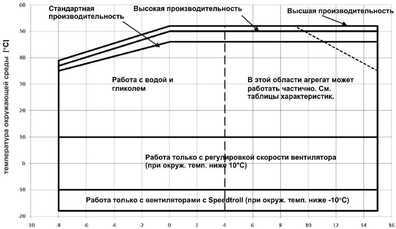
Operating limits
Storing
Environmental conditions must be within the following limits:
Minimum ambient temperature : -20°C
Maximum ambient temperature : 57°C
Maximum R.H. 95% not condensing
Storing below the minimum temperature may cause damage to components. Storing above the maximum temperature causes opening of safety valves. Storing in condensing atmosphere may damage electronic components.
Operation
Operation is allowed within the limits mentioned in Figure 2. The unit must be operated with an evaporator water flow rate between 50% and 140% of nominal flow rate (at standard operating conditions).
Operation out of the mentioned limits may damage the unit. In case of doubts contact manufacturer representative.
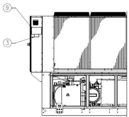
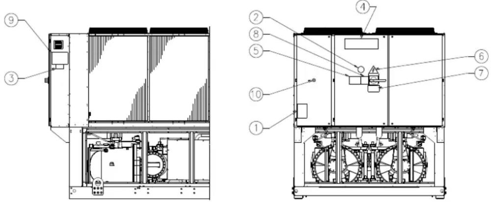
Figure 1 - Description of the labels applied to the electrical panel
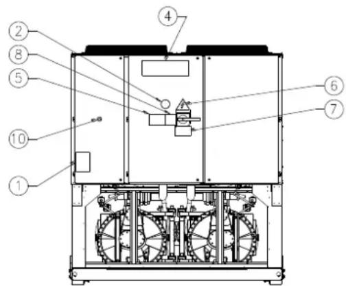
Label Identification
| 1 – Non flammable gas symbol | 6 – Electrical hazard symbol |
| 2 – Gas type | 7 – Hazardous Voltage warning |
| 3 – Unit nameplate data | 8 – Cable tightening warning |
| 4 – Manufacturer's logo | 9 – Lifting instructions |
| 5 – Water circuit filling warning | 10 - Emergency stop |
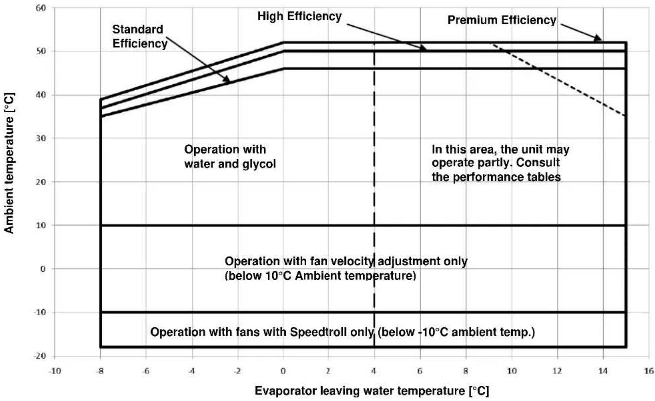
Figure 2 - Operating limits
Safety
The unit must be firmly secured to the soil.
It is essential to observe the following instructions:
- The unit can only be lifted using the lifting points marked in yellow fixed to its base.
- It is forbidden to access the electrical components without having opened the unit main switch and switched off the power supply.
- It is forbidden to access the electrical components without using an insulating platform. Do not access the electrical components if water and/or moisture are present.
Sharp edges and the surface of the condenser section could cause injury. Avoid direct contact and use adequate protection device
- Switch off power supply, by opening the main switch, before servicing the cooling fans and/or compressors. Failure to observe this rule could result in serious personal injury.
- Do not introduce solid objects into the water pipes while the unit is connected to the system.
- A mechanical filter must be installed on the water pipe connected to the heat exchanger inlet.
- The unit is supplied with safety valves, that are installed both on the high-pressure and on the low-pressure sides of the refrigerant circuit.
It is absolutely forbidden to remove all protections of moving parts.
In case of sudden stop of the unit, follow the instructions on the Control Panel Operating Manual which is part of the onboard documentation delivered to the end user.
It is strongly recommended to perform installation and maintenance with other people. In case of accidental injury or unease, it is necessary to:
-keep calm
- press the alarm button if present in the installation site
- move the injured person in a warm place far from the unit and in rest position
- contact immediately emergency rescue personnel of the building or the Health Emergency Service
- wait without leaving the injured person alone until the rescue operators come
- give all necessary information to the rescue operators

Avoid installing the chiller in areas that could be dangerous during maintenance operations, such as platforms without parapets or railings or areas not complying with the clearance requirements around the chiller.
Noise
The unit is a source of noise mainly due to rotation of compressors and fans.
The noise level for each model size is listed in sales documentation.
If the unit is correctly installed, operated and maintained the noise emission level do not require any special protection device to operate continuously close to the unit without any risk. In case of installation with special noise requirements it could be necessary to install additional sound attenuation devices.
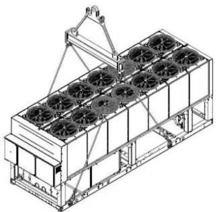
Moving and lifting
Avoid bumping and/or jolting during loading/unloading unit from the truck and moving it. Do not push or pull the unit from any part other than the base frame. Secure the unit inside the truck to prevent it from moving and causing damages. Do not allow any part of the unit to fall during transportation or loading/unloading.
All units of the series are supplied with lifting points marked in yellow. Only these points may be used for lifting the unit, as shown in the following.
Use spacing bars to prevent damage to the condensation bank. Position these above the fan grills at a distance of at least 2.5 metres.

Both the lifting ropes and the spacing bars must be strong enough to support the unit safely. Please check the unit's weight on the unit nameplate.
The unit must be lifted with the utmost attention and care following lifting label instructions; lift unit very slowly, keeping it perfectly level..
Positioning and assembly
All units are designed for installation outdoors, either on balconies or on the ground, provided that the installation area is free of obstacles that could reduce air flow to the condensers coil.
The unit must be installed on a robust and perfectly level foundation; should the unit be installed on balconies or roofs, it might be necessary to use weight distribution beams.
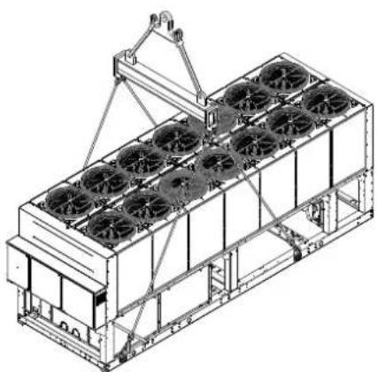
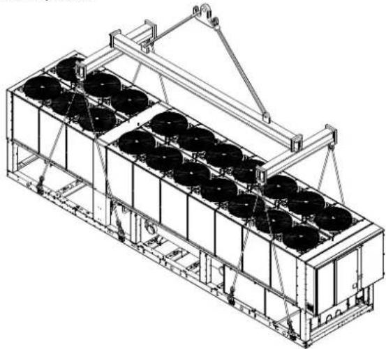
Figure 3 - Lifting the unit
2 compressors unit
For installation on the ground, a strong concrete base, at least 250~mm thickness and wider than the unit must be provided. This base must be able to support the weight of the unit. If the uni is installed in places that are easily accessible to people and animals, it is advisable to install protection grids for the condenser and compressor sections. To ensure best performance on the installation site, the following precautions and instructions must be followed:
- Avoid air flow recirculation.
- Make sure that there are no obstacles to hamper air flow.
- Make sure to provide a strong and solid foundation to reduce noise and vibrations.
- Avoid installation in particularly dusty environments, in order to reduce soiling of condensers coils.
- The water in the system must be particularly clean and all traces of oil and rust must be removed. A mechanical water filter must be installed on the unit's inlet piping.
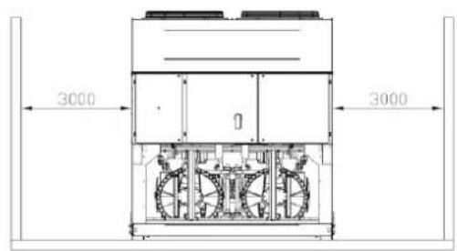
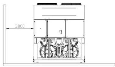
Minimum space requirements
It is fundamental to respect minimum distances on all units in order to ensure optimum ventilation to the condenser coils. When deciding where to position the unit and to ensure a proper air flow, the following factors must be taken into consideration:
- avoid any warm air recirculation
- avoid insufficient air supply to the air-cooled condenser.
Both these conditions can cause an increase of condensing pressure, which leads to a reduction in energy efficiency and refrigerating capacity.
Any side of the unit must be accessible for post-installation maintenance operations. Figure 3 shows the minimum space required.
Vertical air discharge must not be obstructed.
If the unit is surrounded by walls or obstacles of the same height as the unit, this must be installed at a distance no lower than 2500mm . If these obstacles are higher, the unit must be installed at a distance no lower than 3000mm .
Should the unit be installed without observing the recommended minimum distances from walls and/or vertical obstacles, there could be a combination of warm air
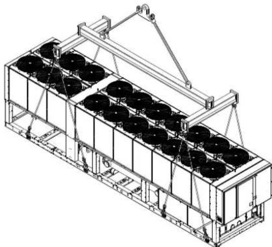
3 compressors unit
recirculation and/or insufficient supply to the air-cooled condenser which could cause a reduction of capacity and efficiency.
In any case, the microprocessor will allow the unit to adapt itself to new operating conditions and deliver the maximum available capacity under any given circumstances, even if the lateral distance is lower than recommended, unless the operating conditions should affect personnel safety or unit reliability.
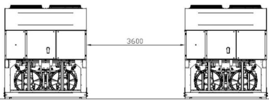
When two or more units are positioned side by side, a distance of at least 3600 mm between condenser banks is recommended.
For further solutions, please consult manufacturer representative.
Sound protection
When sound levels require special control, great care must be exercised to isolate the unit from its base by appropriately applying anti-vibration elements (supplied as an option). Flexible joints must be installed on the water connections, as well.
Water piping
Piping must be designed with the lowest number of elbows and the lowest number of vertical changes of direction. In this way, installation costs are reduced considerably and system performance is improved.
The water system must have:
- Anti-vibration mountings in order to reduce transmission of vibrations to the structures.
- Isolating valves to isolate the unit from the water system during maintenance.
- Flow switch
- Manual or automatic air venting device at the system's highest point.; drain device at the system's lowest point.
- Neither the evaporator nor the heat recovery device must be positioned at the system's highest point.
- A suitable device that can maintain the water system under pressure (expansion tank, etc.).
- Water temperature and pressure indicators to assist the operator during service and maintenance.
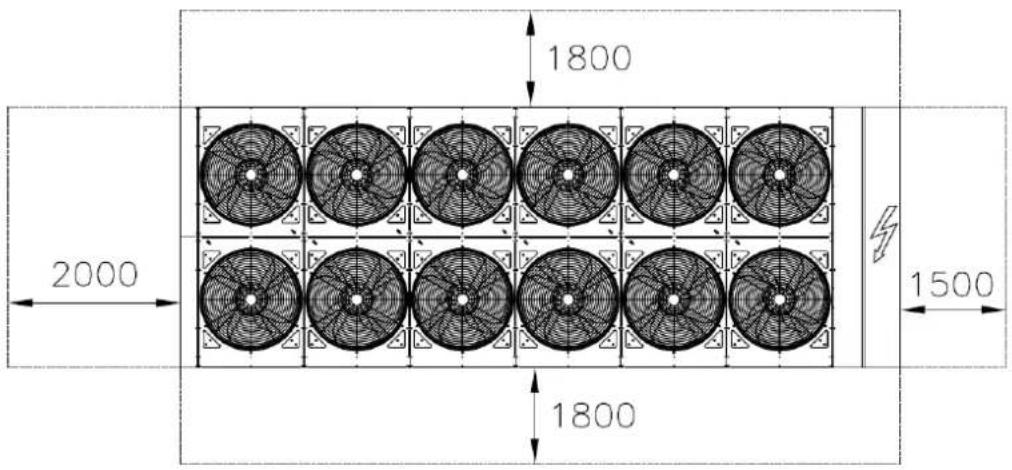
Figure 4 - Minimum clearance requirements
- A filter or device that can remove particles from the fluid. The use of a filter extends the life of the evaporator and pump and helps to keep the water system in a better condition.
- Evaporator has an electrical resistance with a thermostat that ensures protection against water freezing at ambient temperatures as low as -25^ . All the other water piping/devices outside the unit must therefore be protected against freezing.
-
The heat recovery device must be emptied of water during the winter season, unless an ethylene glycol mixture in appropriate percentage is added to the water circuit.
-
If case of unit substitution, the entire water system must be emptied and cleaned before the new unit is installed. Regular tests and proper chemical treatment of water are recommended before starting up the new unit.
- In the event that glycol is added to the water system as anti-freeze protection, pay attention to the fact that suction pressure will be lower, the unit's performance will be lower and water pressure drops will be greater. All unit-protection systems, such as anti-freeze, and low-pressure protection will need to be readjusted.
- Before insulating water piping, check that there are no leaks.
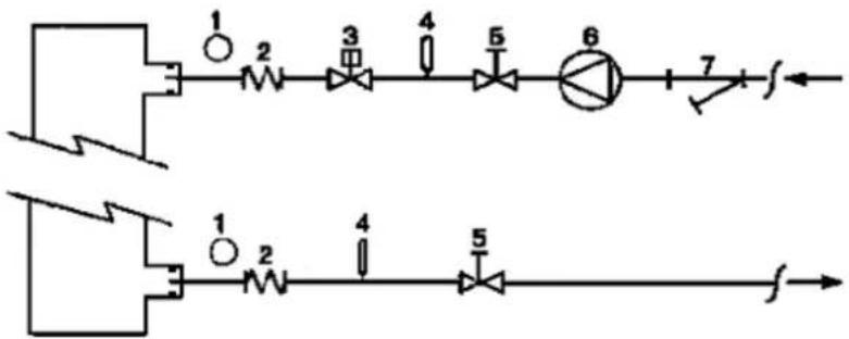
Figure 5 - Water piping connection for evaporator
EVAP
- Pressure Gauge
- Flexible connector
- Flow switch
-
Temperature probe
-
Isolation Valve
- Pump
7.Filter
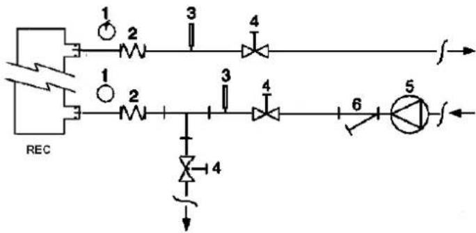
Figure 6 - Water piping connection for heat recovery exchangers
- Pressure Gauge
- Flexible connector
-
Temperature probe
-
Isolation Valve
- Pump
6.Filter
Water treatment
Before putting the unit into operation, clean the water circuit. Dirt, scales, corrosion debriets and other other material can accumulate inside the heat exchanger and reduce its heat exchanging capacity. Pressure drop can increase as well, thus reducing water flow. Proper water treatment therefore reduces
the risk of corrosion, erosion, scaling, etc. The most appropriate water treatment must be determined locally, according to the type of system and water characteristics. The manufacturer is not responsible for damage to or malfunctioning of equipment caused by failure to treat water or by improperly treated water.
Table 1 - Acceptable water quality limits
| pH (25°C) | 6,8÷8,0 | Total Hardness (mg CaCO3 / l) | < 200 | |
| Electrical conductivity μS/cm (25°C) | <800 | Iron (mg Fe / l) | < 1.0 | |
| Chloride ion (mg Cl- / l) | <200 | Sulphide ion (mg S2- / l) | None | |
| Sulphate ion (mg SO4- / l) | <200 | Ammonium ion (mg NH4+ / l) | < 1.0 | |
| Alkalinity (mg CaCO3 / l) | <100 | Silica (mg SiO2 / l) | < 50 |
Evaporator and recovery exchangers anti-freeze protection
All evaporators are supplied with a thermostatically controlled anti-freeze electrical resistance, which provides adequate anti-freeze protection at temperatures as low as -25^ . However, unless the heat exchangers are completely empty and cleaned with anti-freeze solution, additional methods should also be used against freezing.
Two or more of below protection methods should be considered when designing the system as a whole:
Continuous water flow circulation inside piping and exchangers
- Addition of an appropriate amount of glycol inside the water circuit
- Additional heat insulation and heating of exposed piping
- Emptying and cleaning of the heat exchanger during the winter season
It is the responsibility of the installer and/or of local maintenance personnel to ensure that described anti-freeze methods are used. Make sure that appropriate anti-freeze protection is maintained at all times. Failing to follow the instructions above could result in unit damage. Damage caused by freezing is not covered by the warranty.
Installing the flow switch
To ensure sufficient water flow through the evaporator, it is essential that a flow switch be installed on the water circuit.
The flow switch can be installed either on the inlet or outlet water piping. The purpose of the flow switch is to stop the unit in the event of interrupted water flow, thus protecting the evaporator from freezing.
The manufacturer offers, as optional, a flow switch that has been selected for this purpose.
This paddle-type flow switch is suitable for heavy-duty outdoor applications (IP67) and pipe diameters in the range of 1" to 6".
The flow switch is provided with a clean contact which must be electrically connected to terminals shown in the wiring diagram.
Flow switch has to be tune to intervene when the evaporator water flow is lower than 50% of nomila flow rate.
Heat recovery
Units may be optionally equipped with heat recovery system. This system in made by a water cooled heat exchanger located on the compressors discharge pipe and a dedicated management of condensing pressure.
To guarantee compressor operation within its envelope, units with heat recovery cannot operate with water temperature of the heat recovery water lower than 28^ .
It is a responsibility of plant designer and chiller installer to grantee the respect of this value (e.g. using recirculating bypass valve)
Electrical Installation
General specifications

All electrical connections to the unit must be carried out in compliance with laws and regulations in force.
All installation, management and maintenance activities must be carried out by qualified personnel.
Refer to the specific wiring diagram for the unit you have bough. Should the wiring diagram not be on the unit or should it have been lost, please contact your manufacturer representative, who will send you a copy. In case of discrepancy between wiring diagram and electrical panel/cables please contact the manufacturer representative.
Only use copper conductors. Failure to use copper conductors could result in overheating or corrosion at connection points and could damage the unit.
To avoid interference, all control wires must be connected separately from the power cables. Use different electrical passage ducts for this purpose.
Before servicing the unit in any way, open the general disconnecting switch on the unit's main power supply.
When the unit is off but the disconnecting switch is in the closed position, unused circuits are live, as well.
Never open the terminal board box of the compressors before having opened the unit's general disconnecting switch.
Contemporaneity of single-phase and three-phase loads and unbalance between phases could cause leakages towards ground up to 150mA , during the normal operation of the units of the series.
If the unit includes devices that cause superior harmonics (like VFD and phase cut), the leakage towards ground could increase to very higher values (about 2 Ampere).
The protections for the power supply system have to be designed according to the above mentioned values.
Operation
Operator's responsibilities
It is essential that the operator is appropriately trained and becomes familiar with the system before operating the unit. In addition to reading this manual, the operator must study the microprocessor operating manual and the wiring diagram in order to understand start-up sequence, operation, shutdown sequence and operation of all the safety devices.
During the unit's initial start-up phase, a technician authorized by the manufacturer is available to answer any questions and to give instructions as to the correct operating procedures.
The operator must keep a record of operating data for every installed unit. Another record should also be kept of all the periodical maintenance and servicing activities.
If the operator notes abnormal or unusual operating conditions, he is advised to consult the technical service authorized by the manufacturer.
Routine maintenance
Minimum maintenance activities are listed in Table 2
Service and limited warranty
All units are factory-tested and guaranteed for 12 months as of the first start-up or 18 months as of delivery.
These units have been developed and constructed according to high quality standards ensuring years of failure-free operation. It is important, however, to ensure proper and periodical maintenance in accordance with all the procedures listed in this manual and with good practice of machines maintenance.
We strongly advise stipulating a maintenance contract with a service authorized by the manufacturer in order to ensure efficient and problem-free service, thanks to the expertise and experience of our personnel.
It must also be taken into consideration that the unit requires maintenance also during the warranty period.
It must be borne in mind that operating the unit in an inappropriate manner, beyond its operating limits or not performing proper maintenance according to this manual can void the warranty.
Observe the following points in particular, in order to conform to warranty limits:
- The unit cannot function beyond the specified limits
- The electrical power supply must be within the voltage limits and without voltage harmonics or sudden changes.
- The three-phase power supply must not have unbalance between phases exceeding 3% . The unit must stay turned off until the electrical problem has been solved.
- No safety device, either mechanical, electrical or electronic must be disabled or overridden.
- The water used for filling the water circuit must be clean and suitably treated. A mechanical filter must be installed at the point closest to the evaporator inlet.
- Unless there is a specific agreement at the time of ordering, the evaporator water flow rate must never be above 120% and below 80% of the nominal flow rate.
Periodic obligatory checks and starting up of appliances under pressure
The units are included in category IV of the classification established by the European Directive PED2014/68EU.
For chillers belonging to this category, some local regulations require a periodic inspection by an authorized agency. Please check with your local requirements.
Table 2 - Routine maintenance programme
| List of Activities | Weekly | Monthly (Note 1) | Yearly/Seas onal (Note 2) |
| General: | |||
| Reading of operating data (Note 3) | X | ||
| Visual inspection of unit for any damage and/or loosening | X | ||
| Verification of thermal insulation integrity | X | ||
| Clean and paint where necessary | X | ||
| Analysis of water (6) | X | ||
| Check of flow switch operation | X | ||
| Electrical: | |||
| Verification of control sequence | X | ||
| Verify contactor wear - Replace if necessary | X | ||
| Verify that all electrical terminals are tight - Tighten if necessary | X | ||
| Clean inside the electrical control board | X | ||
| Visual inspection of components for any signs of overheating | X | ||
| Verify operation of compressor and electrical resistance | X | ||
| Measure compressor motor insulation using the Megger | X | ||
| Refrigeration circuit: | |||
| Check for any refrigerant leakage | X | ||
| Verify refrigerant flow using the liquid sight glass - Sight glass full | X | ||
| Verify filter dryer pressure drop | X | ||
| Verify oil filter pressure drop (Note 5) | X | ||
| Analyse compressor vibrations | X | ||
| Analyse compressor oil acidity (7) | X | ||
| Condenser section: | |||
| Clean condenser banks (Note 4) | X | ||
| Verify that fans are well tightened | X | ||
| Verify condenser bank fins - Comb if necessary | X |
Notes:
1. Monthly activities include all the weekly ones.
2. The annual (or early season) activities include all weekly and monthly activities.
3. Unit operating values should be read on a daily basis thus keeping high observation standards.
4. In environments with a high concentration of air-borne particles, it might be necessary to clean the condenser bank more often.
5. Replace the oil filter when the pressure drop across it reaches 2.0 bar.
6. Check for any dissolved metals.
7. TAN (Total Acid Number): ≤0,10: No action
Between 0.10 and 0.19 : Replace anti-acid filters and re-check after 1000 running hours. Continue to replace filters
until the TAN is lower than 0.10.
0,19 : Replace oil, oil filter and filter dryer. Verify at regular intervals.
Important information regarding the refrigerant used
This product contains fluorinated greenhouse gases. Do not vent gases into the atmosphere.
Refrigerant type: R134a
GWP(1) value: 1430
(1)GWP = Global Warming Potential
The refrigerant quantity necessary for standard operation is indicated on the unit name plate.
Real refrigerant quantity charged in the unit is listed on a silver sticker inside the electrical panel.
Periodical inspections for refrigerant leaks may be required depending on European or local legislation.
Please contact your local dealer for more information.
Factory and Field charged units instructions
(Important information regarding the refrigerant used)
The refrigerant system will be charged with fluorinated greenhouse gases.
Do not vent gases into the atmosphere.
1 Fill in with indelible ink the refrigerant charge label supplied with the product as following instructions:
- the refrigerant charge for each circuit (1; 2; 3)
- the total refrigerant charge (1 + 2 + 3)
- calculate the greenhouse gas emission with the following formula:
GWP value of the refrigerant x Total refrigerant charge (in kg) / 1000
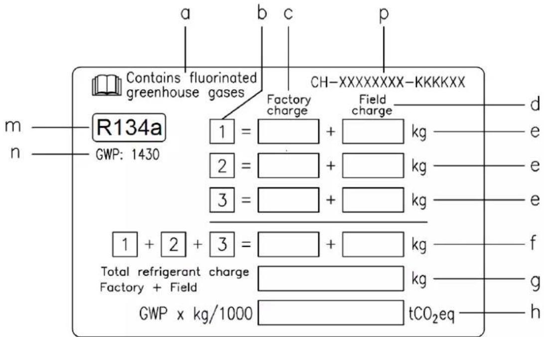
a Contains fluorinated greenhouse gases
b Circuit number
c Factory charge
d Field charge
e Refrigerant charge for each circuit (according to the number of circuits)
Total refrigerant charge
g Total refrigerant charge (Factory + Field)
h Greenhouse gas emission of the total refrigerant charge expressed as tonnes of CO2 equivalent
m Refrigerant type
n GWP = Global Warming Potential
p Unit serial number
2 The filled out label must be adhered inside the electrical panel.
Periodical inspections for refrigerant leaks may be required depending on European or local legislation. Please contact your local dealer for more information.
NOTICE
In Europe, the greenhouse gas emission of the total refrigerant charge in the system (expressed as tonnes CO_2 equivalent) is used to determine the maintenance intervals.
Follow the applicable legislation.
Formula to calculate the greenhouse gas emission:
GWP value of the refrigerant x Total refrigerant charge (in kg) / 1000
Use the GWP value mentioned on the greenhouse gases label. This GWP value is
based on the 4th IPCC Assessment Report. The GWP value mentioned in the manual might be outdated (i.e. based on the 3rd IPCC Assessment Report)
Disposal
The unit is made of metal, plastic and electronic parts. All these parts must be disposed of in accordance with the local regulations in terms of disposal.
Lead batteries must be collected and sent to specific refuse collection centres.
Oil must be collected and sent to specific refuse collection centres.
This man is a technical aid and does not represent a binding offer. The content cannot be held as explicitly or implicitly guaranteed as complete, precise or reliable. All data and specifications contained herein may be modified without notice. The data communicated at the moment of the order shall hold firm.
The manufacturer shall assume no liability whatsoever for any direct or indirect damage, in the widest sense of the term, ensuing from or connected with the use and/or interpretation of this manual.
We reserve the right to make changes in design and construction at any time without notice, thus the cover picture is not binding.
Freecooling Unit Version
Freecooling units have additional coils used to pre-cool the fluid coming from the building and increase the overall efficiency by unloading the compressors until their completely stop if the environments conditions allow it. The water flow can be diverted to the additional coils in case the outside ambient temperature drops below the return water temperature by three way valve (or two single way valves. It depends from chiller size).
Freecooling operation can be enable by QFC switch installed in the control section of the electrical panel. Once the Freecooling function is enabled, the unit controller manages automatically the operation of the water valves. The system controls, also, the operation of fans maximizing the freecooling effect.
ATTENTION
The water system MUST be filled with the proper percentage of Water and Glycol.
It is responsibility of end user to ensure to appropriate amount of Water/Glycol percentage.
Damage of Freecooling coils caused by freezing is not covered by the warranty.
ATTENTION
Install field-provided flow switches with water pump interlock to sense the system water flow.
ATTENTION
To prevent damage to the freecooling coils and evaporator tubes, install a strainer in the unit water inlet piping.
Strainer must have maximum 0,5 mm mesh.
There are two types of freecooling control system:
Freecooling system with 3 Way Valve
EWAD640CF-XS/XL ÷ EWADC11CF-XS/XL - EWAD600CF-XR ÷ EWADC10CF-XR
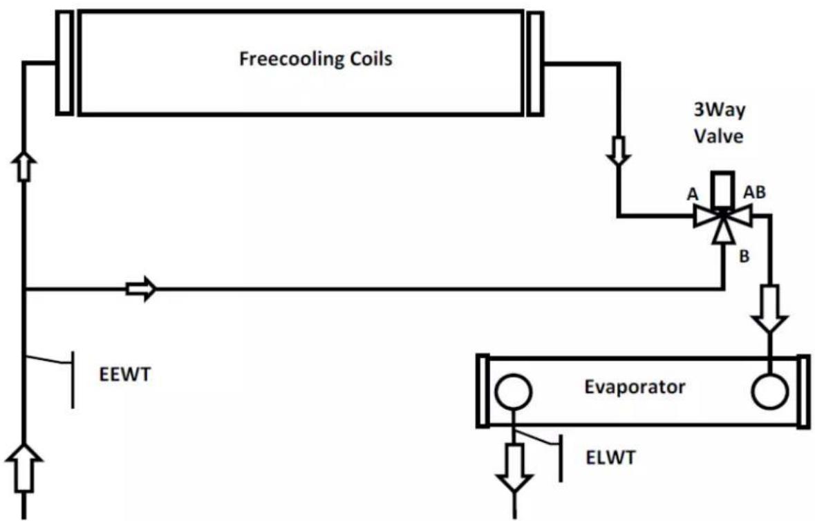
EEWT = Water entering temperature probe
ELWT = Water leaving temperature probe
Freecooling system with 2 Way valves
EWADC12CF-XS/XL ÷ EWADC16CF-XS/XL - EWADC11CF-XR ÷ EWADC15CF-XR
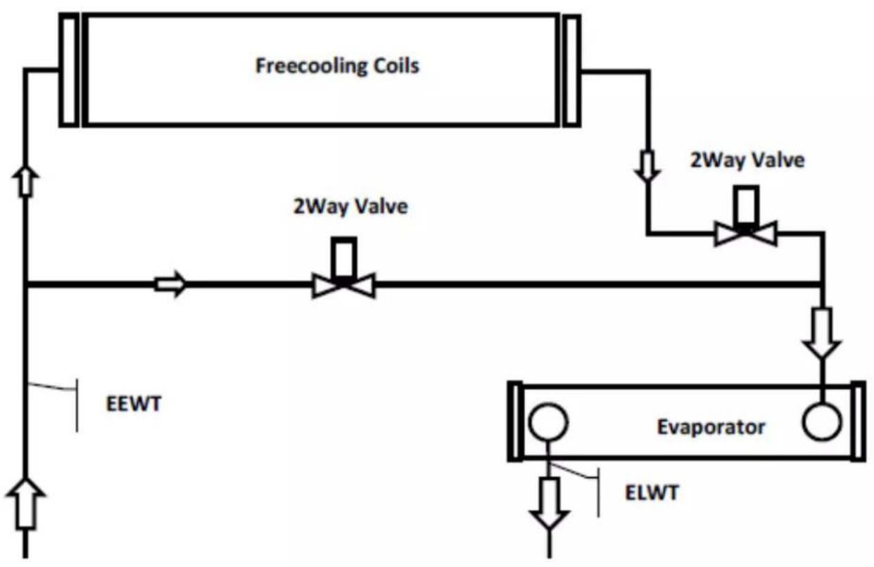
EEWT = Water entering temperature probe
ELWT = Water leaving temperature probe
System change over is controlled by embedded unit controller, depending from operating conditions and unit setpoint. Between winter and summer operation the water side pressure drops are different, consequently the chiller water flow could be different. Evaluate that the minimum and maximum water flow, between summer and winter operation, are inside the water flow limits (see product manual).
(1) GWP = Global Warming Potential (Treibhauspotential)
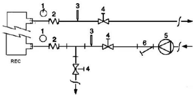
Figure 6 - Water piping connection for heat recovery exchangers
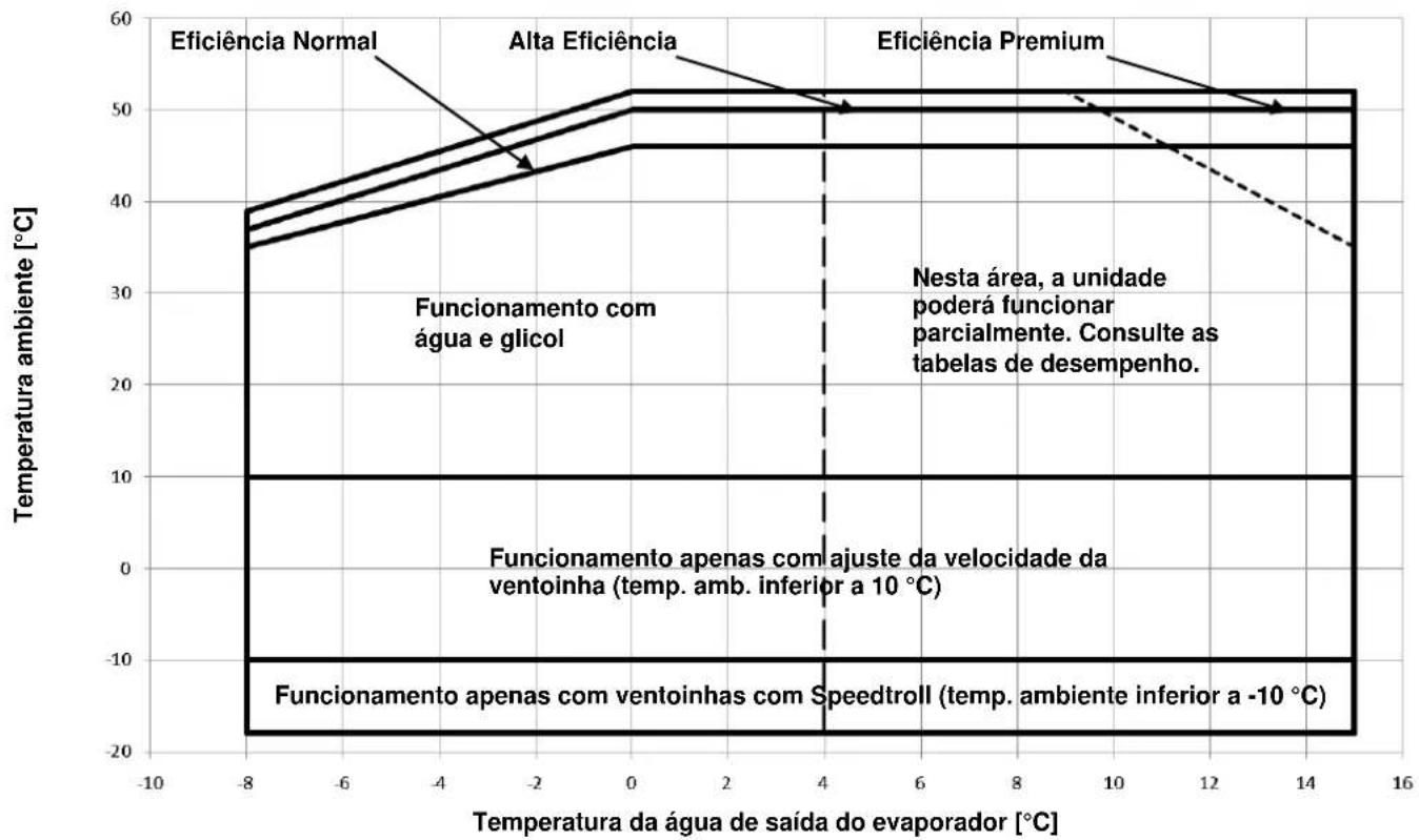
Figura 2-Limits operatives
Seguranca
Enyae paCXOXJENH MEXdy daHHbIMN, COpeKpaUIMMCA H BactoAeM pyKOBOCTB TaHbIMN DOkMeHTOB arperata, npeMuceCTBO IMeHOT DOkMeHTbl, cOpBOXdaIOuHN MaHInHy. B cnyae comHeHn o6pTTeCb K ppeCTabntenIO n3rOToBteIa.
LJIb HactoJue pmyopoe Ta - npocctabHm MOHTAHMy nKanmpupeHOMy nepcoHany Bc0 VnDopmaUHO, He6xOpMnO Dn TpabMbHor O Beconachoro
HIOHNHeYcTaHOBKN,nyckaB3KcnIpyaTaunIO TeXnHyeCKoRO 6CnyKBaHnArpera
Pn noJyueHn arperata
Iocne DocTabn arperata do Mecta OKOHnatelbHOYCTAHOBKn erO Heo6xOIMMO npOBeH Hannme nopeKpHm. POpBepn DnHb npePbaBc Bce KOMnoHbI, nepeuNCleHHbe BOTrp30CHN HaKJIaHNOH.
B cnyae nobpejdeHn arperata He nepemecnte nobpejdeHn maepma, a cpoH Coo6uHTe 0b 3OM TpaHCnopTHoK oMnahanC Tpe6oBaHmE OcMOrpeTb arperat.
HeaewmtnenbHO ncectme npectabnter KOMnHnHPOBQDTER O BbRnBHHbx
NOBpeXdEHHxH, NO Mepe Bo3MOXHOCTn, pniuINTE FOtorpaFm, KOtOpBle MOrTn 6bl RomOy bYcTaHOBNTb OTBeTcBEHOCTh 3a NOpeXdEHH.
PogpenHe He DnHb 6bIb YcPaeHNO Do npoepeHn PnpctaHTenm HHCnOpTHoKOMNaHmOcmToPa arperata.
PpeKd cem npctynb K yctaHOBKe arperata npobepTe, YTO moeJIb H yka3aHHe H TaBnue HOMMHaNbHbIX DaHbIX HanpRjEHN He NtAHHRA BnHOTc npabNtBbIMn. Tocf PnEMKn arperata OTBcTBeHNbOCTb 3a IIObIe NOBpeJedHr He MOKe 6bITb BO3IOKe HA KOMNaHIO-H3rTOBtNEb.
Oncanhe
PnO6pTeHbBnBAM arperat npctCTaRnBt co60y"uNnep C B03dyuHbM OXnAeJeHMeKoHdEHCaTOpA, npDHa3NaueHbI dNn OXnAeHHeNBObl (BoBn BOOrnIKoBeBOH) Hbte bpoOye yCNOBAHnKeyka3AHbIX npDeJELX TEMpePAtpBy. PnpHUn paboTb arperata oChOBBaTaCHa
Inpouce Cxatna, KOndecnun n paacunpeHn IArperat coctoNT H3 cneDyoux OCHOBbIX y3IOB:
-BuHTOBO KOMPpeccop nIIOBbUeHnIaBHeHnIcnapeHnXnadareHTaN, daBHeHnKoHDeHcaun.
- Icnapntenb, B KOTOPOM npoCXOHTN CnapeHne XnKOrO XnaIaReHtA, 3a cyeco6CTBeHHNO npocxOHT OXnJaKeHne BObl.
KoHcHcTOpB, B ToPOM np TpBbXoHMM DaIeHHeM HcHbOpyTeO, oBeIeYnBaBA ydaJIeHHe B aTMocΦepy TeNJa, OTBeHHO rno 13 BoNb, OxN KOTOpO pIPOncxOaNDt B TEINoo6MeMHnke C BO3dyUhBM OxNaXdHeHm.
- PacuPteBbI KJIaHAn DnI NOHKeHn DaBHeHn KOHeHCaun XnKoCTN daBHeHn IcnapenHn.
InΦopmaunouoouxapaktepa

Bce arperatbI noctabnIOCTcB KOMeKHeCKmM CXeMaMn cepTuHnUpoBaHHbIMu YpeTeaHmUkOH HmHaNbHbIX daHHbIX
EknapauneoCOOTBeCByyka3aHHbIeDOKyMeHTbl COepKAT BCETexHueckne daHHbIe npno6peTeHHor
KAPENWE
yBIOBMA xpaHeHnI MMeRt CJIeDyUOuNne oPaHnueHnI:
MHHHBAHTEMNepetaOOKpyKaIouJeroBCpyx :20C
MaKcHmAbHae TempeaTypo OkpyKaioJero B03dyxa :57
OTHOHTBHHBAHIOHOCTb 95%(6e3KHeHcalu)
XpaHHeHne npT TemnepaType HnKHe MNHMmaIbHOJ MOKe TcTaB pNpMHNO IOBpeJeHN KOMNoHEHTOB arperata. XpaHHeHne npT TemnepaType Bblse MaKcMmaJIbHOJ MOKeT
PvBecnK O TpBIOI nppeoepaehnHbK KnaHOB XpaHHe KOHeCPOyLaeX
CPOE MOXET CTaTb npuHNOH NOBpeKJeHnA JAEKTPnueCKNX KOMNoHEHTOB.
Babota
IpeelbHbIe pa6oue ycnoBn arperaTa noka3aHbHa PucyHke 2.
Pn3KcNpyataun arperata paXoD B0dyB NcnapTeNe DOnKeH CoCTaBnTb He MeHe 50% Hne 6oee 140% OT HOMHaIbHorO paXoDa (pnpctanapThbIX pa6OuX ycNoBm
Pa6ota arperata BHe yka3aHHbIX ppeJeIOB MoKeT npNBecTn K ero NOBpeKDeHIO.
B cnyuae comHenm 6paTnTeCb K npedctabntEnIO n3rotobnteIa
Pncyho1-Onncahne Ta6nuek,ycTaHOBneHHbIX Ha 3NeKtpuecko PaHei arperaTa (3neKtpueckar naHeJIb MOKeT 6bITb DByx pa3HbIX BicOTax)
NdeHTnФнkaUra Ta6nueK
| 1-CsMbON "HeBocTnAmeHauMcyra" | 6-CsMbON OToaCCTn IoparKeHbA 3eKeTpIeKHM ToKOM |
| 2-TmIraZa | 7-П overdурждение OHarIMM OToaCHor OHaPRAHbEeHb |
| 3-TaBIMHa HOMMHaJIbIXdAnHbIX apererata | 8-П overdурждение OHeCbXoDmOCTN KOHpTnBaTlBaHbNkAbTei |
| 4-JIorotm KOMnAHmHProVbOvIeRЯ | 9-YkaZaHnO no PtoBemy apererata |
| 5-П overdурждениe OHeCbXoDmOCTN 3aOpIHbHbWBoDAHrO KoHtypa | 10-AbapmHbI ocTaHOB |
PucyHok 2 - PpeJeIbHbIe pa6oOne 3NaueHn
Temnepatypa BoDbHa BbIXOe nCnapntTej [°C]
TexHnka 6e3oNaCHOCTN
Arperat donjken 6bItb hAdexKho 3aФнкupoban Ha nony.
HnKepeueCnEHHbIe HNCTpyKUIN NOJnEJaT HeyKoCHHTbHOMy BblOnHeHIO:
Iopbem aperata MoHET 6ttb ccyueCTBnH TOnbO C NOnb0BaHEM
PpeDyCMToeHHbIX DnA 30I TcN TaeJaXHbIX ToeK Ha OChOBaHN arperata
OTMeueHHbIX XeJIbIM LBeTOM.
-Bo n36exaHHe TpaBmI He CneJeYeT npKacaTbC K OcTpBIM Kpaam N NobepxFepccOPOB IN BHTnIaTOPOB.
- Pn npOBeHnn paobc 3neKtpueckm KOMnoHeHTamn npedBapnten o6ecToHTb arperat,pa3OMKHyB pyuNBHK.
-3aPpeaaeTcnpoBOntpa0bToC 3JKeTpUwecknM KOMNoHETaMn 6e3 M0JIaIOHOHbIX NOCTabOK.He DOnyCkaTeT npOBoiNb pa0bTo C 3JKeTpUwecknM KOMNoHETaMn PnHaNmMn MOKpbIX ININ BnAxBX NOBepxHOCTeN.
KOHHeHcTopa, a TaKKe Heo6xOIMO nCnOlb30BaTb HaIeKaIe 3aIyRyBb Mya THepyEmoTO OTeBbM MmoEEMN yKaab H TeXHHeCO
CpeCTBa. DOKyMeHTaUIM
- Peped npoBeHem pa6ot no TexHueckomy 06cnyKBAHIO BEHTnIaTopoB 1PabibbOM BnonHeH yTahOBu, KcNpyatauM I TexHoeO
KOHdHcTopa n(IIIN) KOMnpeccopOB Heo6xOIMO NOJHOCTbIO OeCTBQyKBAHN, Wym, pOn3BOIMbI arperaTOM He Tpebyet npImHeHn CneunAJIb arperaT, PaoMkhvB VpMbHk. HeBbIpONHeHne DaHHOrTOpe6BaHn MHTbIX CpeCTB PPn PPOJOKNTeHbHO paObe PraDM C Hm.
CTaB PnHmHO CepHe3HO TpABMn Ipi HnHmCneunalbHex Tpe6oAHm K ypoBHIO Wyma MoKet BO3HKNHYb
HIOIOIOHOHNOOIOHOHOHOHOHOHOHOHOHOHOHOHOHOHOHOHOHOHOHOHOHOHOHOHOHOHOHOHOHOHOHOHOHOHOHOHOHOHOHOHOHOHOHOHOHOHOHOHOHOHOHOHOHOHOHOHOHOHOHOHOHOHOHOHOHOHOHOHOHOHOHOHOHOHOHOHOHOHOHOHOHOHOHOHOHOHOHOHOHOHOHOHOHOHOHOHOHOHOHOHO HO HO HO HO HO HO HO HO HO HO HO HO HO HO HO HO HO HO HO HO HO HO HO HO HO HO HO HO HO HO HO HO HO HO HO HO HO HO HO HO HO HO HO HO HO HO HO HO HO HO HO HO HO HO HO HO HO HO HO HO HO HO HO HO HO HO HO HO HO HO HO HO HO HO HO HO HO HO HO HO HO HO HO HO HO HO HO HO HO HO HO HO HO HO HO HO HO HO HO HO HOOHOOHOOHOOHOOHOOHOOHOOHOOHOOHOOHOOHOOHOOHOOHOOHOOHOOHOOHOOHOOHOOHOOHOOHOOHOOHOOHOOHOOHOOHOOHOOHOOHOOHOOHOOHOOHOOHOOHOOHOOHOOHOOHOOHOOHOOHOOHOOHOOHOOHOO
- Pn noCoeHHeHn arperata K mdpabHuecko cnCTeMe Heo6xo
IpeoTbpaTb nonaHaHe NoCTOpOHnX npEMeTOB B NHHIO BObl.
- Ha JINHIN BOJBI NEpeB BXODOM B TeNIOOMeHHNK peKOMeHNyETcY cTAR
MexAHuecknФЛьТР.
- Arperat ochaaetcnpedoxpahnteHbHMKnanaHAMn,ycTaHaBnBaembHbHBAHIO. Ptp TaHcnopTpOBke arperata Heo6xOIMMo 3a6NoKpObaT bero
KoHTy XnadaTeHa cTOpOHax BbICOKOr N H3KOr DaBHeHr. TpaHCnOtpTHOM CpeCTBe BO n36eKaHMe BO3MOXHO r CKOnJbKeHn I NOBpeXJIeHI
Kateropnueckn 3anpeaaetc nHt b 3aunthbte orpaxdeHn noBx6xOJIMO taKke coBIOdaTb octOpoxHOCT, yTObI BO BPEM daHHbIX Oepauin
opraHOB.
B cnyuae Bhe3anHoi octaHOBKn arperata cneDyRyKoepoepoepno no
3Kcnnyataaun naneyn npabnneo B coCTaB DOkyMeHTaUN, KOtopa
NocTabnEeTcBMeTe C arperaTOM.
yEeHnBHO pKoHmOHyETor npBQyIb pAbOtI no yCTaHoBe N TeKHeXcM
06cnykuaHIOB pncyTCTBnDpynx IHOeI. PnHecuactHom Cnyae p
BbINHHTcEduOuue DeICTBIA:
CoXpaHrTb CnOKoNCTBne
HawatbKnYyabapmHoiMnHaMzJN (npie HnHaMeCTe MoTaKa)
PepenecmnoctpapabBbEBOBTEINOEMeTcNOaBbEOTarperata
HemepenHcBbTaC npcoHOM HeTOnHn nOou 3aogda Vm Bbl3BaTbCKopyIO NMOU.
A0: DkDgBcBnnpbBnncnepuBnncBocpOnnmouPnnpcmCnocpabllmm.
PepocctabimBBOHeoOxQmMVOHcpmaIIO.
He cneJeYcTaHaBnBaTb YInNep B MecTax, KoToPbIe MOrY 6blTb NOTEHnJIbHO OAnChbl Iy npOBEdHnI TexOBCJyXJBAHnI, HApNIpep, H nIaTfOpMax 63 nepnI nnHa INoUaAdkax C HeIOCTaTOHyBM CBO6oDhIM npocTpaCTBOM BOKpyr YInNepa.
Ulym
ArperaTraTcHcyHOMyMa,ReHeppyemoro,naBbIMo6pa30m,pao
XeepccopoB IN BENTNATOPOB.
ypeh b LyMa THeepmyo OTeBbM MOpEPMY, yaaH B TexHaeON
DOKyMeHTaUIM
PnnpabNbHm BnonHeHm yctahOEM, 3nnyatauM nTexHedoro
TQKBAHNA, WYM, PON3BODIMbI arperaTOM He Tpe6yET npMHeHn CneluaJIb
JauHbX CpeCTB pRn npoDJIKHeJbHO pa6Ote PAOMC
Tprn HauuHn CneuaHbHx Tpe6oBaHm K yPoBnO Wyma MoXeT BO3HKnHytB
Hc06xDmOCTbYCTAHOBDMONHNTeBbX3yBNOMPOMyOLXyCPToCTB.
Iopbem m npepemeuenhe arperata
BbBbBbBbBbBbBbBbBbBbBbBbBbBbBbBbBbBbBbBbBbBbBbBbBbBbBbBbBbBbBbBbBbBbBbBbBbBbBbBbBbBbBbBbBbBbBbBbBbBbB
Ibberb tonho n Tpam aperaT. ynnn Dnwn Hn npnnabbaBc0r tonko
BbAHIO. Pn TpaHcnopTnpOBKe arperaTa Heo6xOIMo 3a6JOKIpOBaTb er0
TpaHCnOpTHOM CpeCDtBe BO n36eXahme Bo3MOxHOro cKoJIbXeHnI N NOBpeXdHI
6xOIOMO TAKKE COBNOaTb OCToPoxHOCTb, YTObI BO BpMa DaHbIX Opeauin
MeTPOB Dpyr OT dpyra
DyTbemHbI TpoCbI TpaBepcbIOJXHbIMeTb IpOuHocTb, HeoXoDmyIO
BbIePKNBaHnBeCa n 6e3onachoro noDbema arperata. Bec arperata
PnBedeH Ha COOTBeTCTByIOUeI NDeHTNΦKauNOHHo TabnueKe.
Apereat cneNyet noHNMaTb OeHb octopoxHo npCobIOdeHn HcTpyAperaT DOnJKe YCTaHABINBaTcRa Ha npOCHM n pacnoIooKHeHOM CToPO npBedeHHo HA COBTBeTcTBouOe Ta6nue. N36eTaB BCTpXuBAHn, n CTpaTaTalBO OCHOBAHm. B Cnyae yCTaHOBKn Ha bAlKOHX mN qepdaKax, To CnOCyUeCTBnTb NoBem MeMeHHo n POBHO. NCNoJIb3OBaTc NeuaNaHbHe BAnKn dnn pabunbHorO paCnppeJeHn BEca.
MOHTaXHaNo3n
Aperatbl npepnneHbI nna HapynHou yctanBm - Ha Teppace mnn HenoepdTeHHo HA 3emne - B Mecax, dpe oceeneBaetor GeonpenrTcBeHHb I DOCTyN BO3dyxa K KOHeHcaTopam.
PcyHok 3-NoDbem arperata
YcTaHOBka c 2 KOMnPeccopamu
YcTaHOBKa c 3 KOMnPpeccopamn
IpyyctahOBKe Ha 3eMnIO DOJXKeH 6bITb 3aJoxKe H6ToHHbI yHdAmEHMe He MeHe, daxe B cnyae ecn paCCTOHIN Do 6OKOBxippeTCTBn He TOnuHHO He MeHee 250 MM, BbICTyaHouin no uInpHHe 3a OCHOBAtBeTcByOT peKOMeHdyEMbIM, MmPonpoUeCOOPHarO CTema
Unnnepa. FyHdAmEHT DoJxKe H6bAaTb DOCTaTOHNO HeCyuey UpaBHeNna IOBOBnTb OBMOH My
Cnooc6hoCTbIO, YTObbl BbIDepkAteBecarperata. npOM3BOJNTeNBHOCTb arperata B daHHbx AHOMaJIbHx ycNoBnx paBoTI b63
Ecni arperat yCTaHaBnBaTeCB N IERKO DOCTyHOM DnI NODei N XJBOTyB3bl DnI Be3oNaChOEtN 6cbNyKBauOero nepcoHana n
MeCeT, To Heo6xOIMO orpaDITb TENIOoMeHHNK IN KOMnPecccop pa6otocno6hOCTn Yrllnpa.
3aUTHbIMn ORApKaDeHnMM. KoDa Pda Nm Boee aperata paoTIOKeHbI qDIN prDCOM C DpyMM,
DnI oBeceNeHn Tpe6yEmbIX 3cKnIpyaTaIOHHbx XapaKTEpNCtIK arperppeoHMeYETc, TIObI paCToHHe MEky TEIOOOMeHHNAMM
Heo6xOIMO CO6NIOaTb CneDyUoine Tpe6oBAnH: KOHDcHATopa CoCTABNlHO He MeHee 3600 MM.
- Bcayx, BbODAuM IN BEHTTNTOPOBHEoTKeHpeLpKynIpOBaTb. B clyae DpyrNx BapnaHTOB yCTaHOBKn ObpaauTeCb 3a KOHCytBaTuueN K
- HanytnBOOduHOro Notka He DoTHNO 6bITppeTCTBn. PpeCTaBntELHO fIPMbI-N3TOTOBNTeJIra.
XnaaareHT coepknt fTopnpoBaHHhe. He cneyet ocuieCTbBbIbpc ra30B b aTMocpepy.
Tn xnaaereHTa: R134a
Ioka3aTeNbGWP(1): 1430
(1)GWP = ΠoTeHuaJΓIo6aIbHoro
IotenJIeHnIa
Heo6xOIMoe KOJInueCTBO XJaadareHt aYka3aHO Ha IeHTnФKauuOHHo Ta6NHyKe arperata.
KoHnEeBc0 cOepkauerocB aperate xnaaereHTa nkaaHO h cepepcTOn JInHeKe, yctahOBHeHHo BHytpnHaenmynpaBHeHr.
BoaMoxHa HeoXOIMocTb npOBeHnI npOBepok Ha HAnHMe yTeHek XnapareHt (noEBpOneKmIM nDpyMM MeCTbIM 3aKaOHAM).
Hnctpykunno o6paueHHo c arperaTamn, 3apxkeHHbIMn Ha 3aBode n Ha 06BeKeTe
(BaxHaa INΦopMaIg OTHOCTeIbHo IcNoJIb3yEmOro XnaIaIareHTa)
Cnctema xlaaareHt 6ydt 3apxkeHa fTopnpoBaHHbIMn napHKOBbIMn ra3amN.
He donyckaTb Bbl6poca ra30B b aTMocfepy.
1 INcno3y HeCMBiBaEMbIe cepHnla, 3aONHnTb 3TNKETky 3apraXnaIaIeHTa B COOTBETCTBm CO CneNyUoien HNCTpykUnei:
- yka3aTb 3apd xnaDareHtda nla KaKdOro KoHTypa (1;2;3);
- yka3aTb 6oBn 3apd xnaDareHa (1 + 2 + 3).
- BBIHCINITb BbIOpocbl npHnKOBbIX ra3OB no φoPMyJe:
3NaueHne IITI xJaIaIeHTa X o6uN 3apd xJaIaIeHTa (B KINorpaMMax) / 1000

aIpncytCTBneΦTOpnpoBaHHbIX npHnKOBbIX ra3OB
b Homep KOHTypa
c 3aBOdcko3apn
d 3apnHa o6bekTe
e 3apxnaaareHTa JnKkDoro KOHtpya (B COOTBETCTBNC CYNCLOM KOHTyOB)
f O6uH 3apd XlaDareHTa
g O6uH 3apJxHaIaIareHTa (3apJ Ha 3aBoe+ 3apJ Ha o6bKeTe)
h Bb6pocbl napHkoBbix ra3OB nIy oIe 0eTo 3apJe xnaIaIeHTa, BbipaxKeHHbIe
B ToHHax B nepeceTe Ha CO2
m Tn XnaIaIareHtA
n GWP = noteHuaan rno6aBho ro nToenHeHH (nT)
p CepnHbI Homep arperata
2 3anonHeHHyO 3nKeTky npNKneNtB BHyTpN 3NeKtpueckoro uHaTa.
COrnacHO eBponeNcKOMy nH MeCTHOMy 3aKoHOnaTeJIbCTBy, Ha 3OT arperat MoryT pacPiocptpaHrTbcra Tpe6obAHnO npEpoNDmueckOn npOBepKe Ha OTCyTCTBne yTeuek XnaDareHTa. DononHInTeIbHyO INΦopMaunIO MOXHO NOnyHTb y MeCTHOrO dInepa.

DPMMEYAHNE
3NaueHHe Bb6pocOB napHKOBbIX ra3OB, 3aBncaJee O oBJeO 3apJa XlaIaReHTa B CnCTeMe
N BbipapaKaemoe B ToHHax B nepeChTe Ha CO 2, NcNoIb3yETcB Ebpone npn OnpeJeHm INTepBaIOB TEXHueCKOrO obcyKmbAHn.
Co6HIOaTb npIMeHMbIe 3aKoHOaTeIbHbIe HOpMbI.
Opmyla dny BbIHCNEHNA BbIbpcOB napHKOBbIX ra3OB:
3NaueHHe IIT XnadaReHTa x 06uI 3apJxnaadaReHTa (B KINorpaMmax) / 1000
Heo6xOIMO nCNoJIb3OBaTb 3aueHHe NII, yka3aHHoe Ha 3tNKeTke npHkoBbIX rA3OB. DAnHoe 3aueHne IINI NOJyueHO Ha OCHOBE MaTePnAIOB 4-TO 3KcNEpTHOrO OTeTA MExKnPaBnteNbCTBeHHoN KOmCCNn No N3MeHeHIO KImMaTa. Yka3aHHoe B pyKoBOdCTBe 3aueHHe NII MoKET Oka3aTbCyaCTapeBwIM (HaNPIMep, NOnyueHHbIM Ha OCHOBE MaTePnAIOB 3-TO 3KcNEpTHOrO OTeTA MExKnPaBnteNbCTBeHHoN KOmCCNn No N3MeHeHIO KImMaTa).
IJIIOJUeyHINIOJIObHOINHOpMaUNO6paauTeKMeCTOMHy IpeCTaBtEnIOIOCTaBUNka.
YTNIN3aUN
Arperat VrotoBneH IV MetaIIHeckix, nactMaccoBbIX 3eKtpoHHbIX KOMIOHEHTOB. KOMIOHEHTbI DOnXbI 6bITyTINNIPoBaHbIB COOTBETCTBM C MecTHbIMnpabuJAMn HOpMaMn.
CBNIOBbIe AKKMyJrTObpI DOJIKNHbI yTNJIN3nPOBaTcR OTeJIbHO.
Macno Heo6xOIMO 06mpaTb B cneuunabHbIe EMKCTN OTTPaBtB CneuunabHbIe IeHTpbIO6pa60TN OTxOIOE.
Installing the flow switch
Installation av flodesmataren
Periodic obligatory checks and starting up of appliances under pressure
The units are included in category IV of the classification established by the European Directive PED 2014/68/EU.