FWG05AT - Air Conditioning DAIKIN - Free user manual and instructions
Find the device manual for free FWG05AT DAIKIN in PDF.

User questions about FWG05AT DAIKIN
0 question about this device. Answer the ones you know or ask your own.
Ask a new question about this device
Download the instructions for your Air Conditioning in PDF format for free! Find your manual FWG05AT - DAIKIN and take your electronic device back in hand. On this page are published all the documents necessary for the use of your device. FWG05AT by DAIKIN.
USER MANUAL FWG05AT DAIKIN
Operating Manual Handset Wireless
1) Type: AAA.R03
2) Quantity: 2 pieces
Disposal Requirements (For European Union (EU) only)

The batteries supplied with the controller are marked with this symbol
This means that the batteries shall not be mixed with unsorted household waste.
If a chemical symbol is printed beneath the symbol, this chemical symbol means that the battery contains a heavy metal above a certain concentration.
Possible chemical symbols are:
■ Pb: lead (>0,004%)
Waste batteries must be treated at a specialized treatment facility for re-use. By ensuring correct disposal, you will help to prevent potential negative consequences for the environment and human health. Please contact your local authority for more information.
Pile
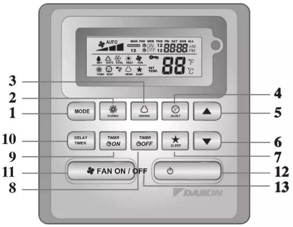
BRC51A61/62 Controller Indication
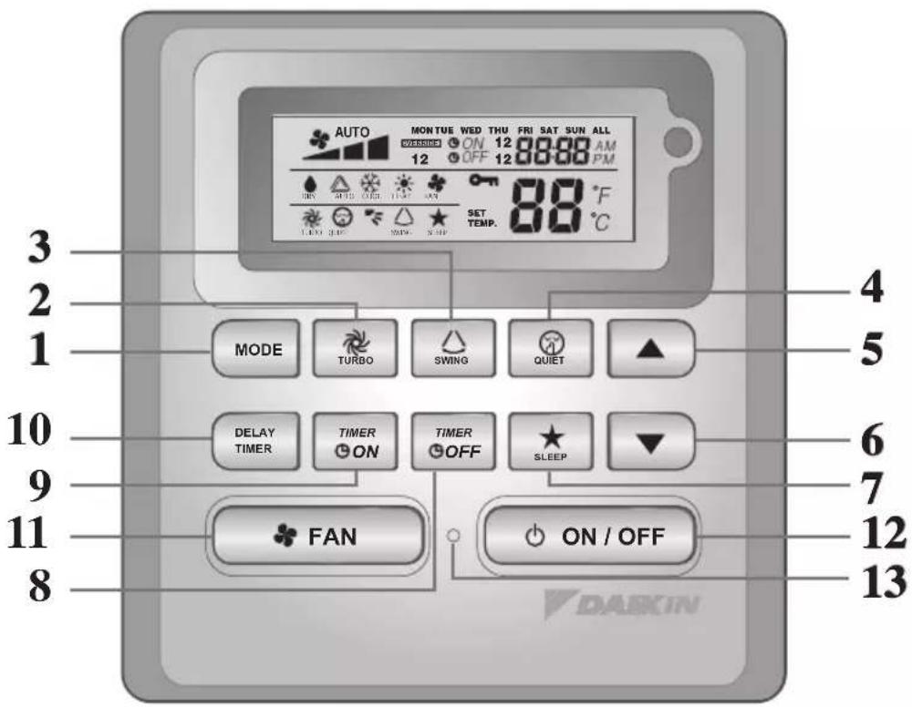
text_image
AUTO MONTUE WED THU FRI SAT SUN ALL OVERSIDE ON 12 88:88 AM 12 OFF 12 PM SET TEMP. 88 °F TOLER SWEET SWEET MODE TURBO SWING QUIET ▲ DELAY TIMER TIMER ON TIMER OFF SLEEP ▼ FAN ON / OFF 4 5 6 7 12 13 3 2 1 10 9 11 8 DAIKIN| NO | KEY FUNCTION | |
| 1. | MODE Select operating Modes control (Cool/ Heat/ Auto/ Dry/ Fan) | |
| 2. | TURBO Activate/deactivate Turbo function | |
| 3. | SWING Activate/deactivate Swing controlHold Key to change Swing Mode | |
| 4. | QUIET Activate/deactivate Quiet function | |
| 5. | SET TEMP UP Increase set temperature in °C or °F | |
| 6. | SET TEMP DOWN Decrease set temperature in °C or °F | |
| 7. | SLEEP Activate/deactivate Sleep function | |
| 8. | OFF TIMER Enable/disable the Event 1 and 2 OFF TIMER setting mode | |
| 9. | ON TIMER Enable/disable the Event 1 and 2 ON TIMER setting mode | |
| 10. | DELAY TIMER Activate/deactivate delay timer | |
| 11. | FAN | Select Fan speeds control (Auto/ High/ Med/ Low) |
| 12. | ON/OFF | On/Off the unit with overriding all the timer settings |
| 13. | REAL TIME CLOCK (RTC) | Enable/disable the Real Time Clock (RTC) setting mode |
NOTE:
Turbo and quiet function are for selected models only.
Press the MODE button to switch operation from COOL, HEAT*, AUTO*, DRY*, FAN. Check the display to see in which mode the control is set. *HEAT, AUTO and DRY are available for selected models only.
1.2 TURBO Fan Speed
Press the TURBO key once to activate Turbo fan speed. Turbo symbol will be shown. To disable Turbo fan speed and back to previous fan speed, press the Turbo key once again. If user presses the FAN button or QUIET button or turn off the unit, the turbo speed will be disabled. This speed is only valid during COOL and HEAT mode for selected models.
1.3 Automatic air swing
- Press the SWING button to activate the automatic air swing function.
- To distribute the air to a specific direction, press the SWING △ button and wait until the louver move to the desired direction and press the button once again.
Swing mode selection method (model dependent)
- Press SWING (☐) button for 4 seconds to enter field setting mode. While in field setting mode, it will only show SWING MODE (✗)
- Press temperature ▲ and ▼ button to select SWING MODE (◀) rotation from Swing Mode 1 to Swing Mode 3.
• There are 3 different SWING MODE, which are:


Swing mode 1 Swing mode 2 Swing mode 3
SWING MODE will not activate unless SWING is activated.
Swing is indicated by the logo:
- If no mode changes within 4 seconds, unit will operate according to the selected SWING MODE (◀).
1.4 QUIET Fan Speed
Press the QUIET key once to activate Quiet fan speed. QUIET symbol will be shown. To disable Quiet fan speed and back to previous fan speed, press the QUIET key again. If user presses the FAN button or TURBO button or turn off the unit, the quiet speed will be disabled. This speed is only valid during COOL and HEAT mode for selected models.
1.5 “▲” or ▼” Set Temperature Button
Press the temperature button and set the temperature of your choice by pressing “▲” or “▼button once, temperature changes by 1°C or 1°F. The default temperature setting range is from 16°C to 30°C (60°F to 86°F). When the Option 20 - 30°C is set, the temperature range limit is set to 20°C to 30°C (68°F to 86°F). Pressing both keys simultaneously will toggle the temperature setting between °C and °F. No temperature setting is allowed during FAN mode (No set temp display). There is no room temperature display.
1.6 SLEEP Function
Press the SLEEP button to activate the sleep mode. SLEEP function is not available in DRY mode and FAN mode.
1.7 "ON TIMER" and "OFF TIMER"
The unit has 2-event timer, namely Timer 1 and Timer 2, each event has an ON TIMER and an OFF TIMER. The key press activity for Timer ON and Timer OFF is shown on Table 1.1
Table 1.1: Timer ON and Timer OFF key press and event sequence.
| TIMER ON KEY TIMER OFF | KEY | ||
| ON Timer 1 ON | Timer 2 OFF Timer 1 OFF Timer 2 | ||
| Deactivated Deactivated | Deactivated Deactivated Deactivated | ||
| Activated Deactivated | Activated Activated Deactivated | ||
| Deactivated Activated | Deactivated Deactivated Activated | ||
| Activated Activated | Activated Activated Activated | ||
All timers are event-triggered timers and can be overridden by the ON/OFF button and Override function.
Set Event 1 and Event 2 Timers
Process for Timer ON and Timer OFF is the same.
- Press and hold Timer ON/OFF key for 3 seconds to go into timer setting mode.
(Icon ON 1 or OFF 1 will blink) - Press UP or DOWN to select Timer 1 or Timer 2 to set.
('1' blinking indicate that Timer 1 is currently selected, '2' blinking indicate that Timer 2 is currently selected) - Press Timer ON/OFF key again to confirm. (Day will blink next)
- Press UP or DOWN to select the day.
- Press Timer ON/OFF key again to confirm the day. (Hour will blink next)
- Press UP or DOWN to change the hour.
- Press Timer ON/OFF key again to confirm the hour. (Minute will blink next)
- Press UP or DOWN to change the minute.
- Press Timer ON/OFF key again to confirm the minute.
Each timer (Timer 1 ON or Timer 1 OFF or Timer 2 ON or Timer 2 OFF) will only be set separately after all 7 steps, if there is no key operation for 5 seconds during setting the timer, it will automatically exits from setting mode and no changes will be made.
ON/OFF timer will be checked every 1 minute.
It is not advisable to set ON TIMER and OFF TIMER to have same values. Shall these occur, the effective timer will be treated with priority as stated in Table 1.2.
Example:
ON TMR 2 settings: DAY - TUE, TIMER - 5.00pm
OFF TMR 1 settings: DAY - TUE, TIMER - 5.00pm
Outcome when RTC reaches 5.00pm on TUE:
- when unit is on, no respond.
- when unit is off, unit will trigger to on.
Table 1.2: Timer Priority
| Priority Timer | |
| 1 (Highest) ONTMR2 | |
| 2 OFFTMR2 | |
| 3 ONTMR1 | |
| 4 (Lowest) OFFTMR1 | |
Upon IR reception, IR wireless remote controller will override ON TIMER 2 and OFF TIMER 2 settings.
1.8 DELAY TIMER Function
Press the DELAY TIMER key once will activate the delay timer function for 1 hour. An indicator “OVERRIDE” will show on the LCD. Press the same key again will increase the setting to 2 hours. An indicator “OVERRIDE” will be shown. Subsequent press will deactivate the delay timer function. After the delay timer is completed, the delay timer function is deactivated and the logo is OFF. All other timers will be resumed.
1.9 FAN Speed Function
Fan speed can be changed via pressing the FAN key:
$$ \text { Low } > \text { Med } > \text { High } > \text { Auto } > $$
*FAN speed is not available in DRY mode.
1.10 ON/OFF Button
Starting Operation:
- Press the ON/OFF button, the LCD will show full display and the unit is turned on.
Stopping Operation:
- Press the ON/OFF button, the LCD will show real time clock only and the unit is turn off.
1.11 Power up Settings
The unit will start up with main board's last state setting during power up. If last state information is not available, the unit will use the default settings. The default settings are as below:
Unit: Off
Mode: Cool
Fan Speed: High
RTC: 12:00AM, MONDAY
Swing: Off
Swing Mode: Standard
Timers: Disable
Turbo: Disable
Quiet: Off
Sleep: Off
Override: Disable
1.12 Real-time Clock (RTC) Display
RTC is shown on screen during the unit ON or OFF except for power failure or error code.
Set RTC Setting
- Press RTC key one time will activate RTC setting mode. (Day will blink)
- Press UP or DOWN to select the day.
- Press RTC again to confirm the day. (Hour will blink next)
- Press UP or DOWN to change the hour.
- Press RTC again to confirm the hour. (Minute will blink next)
- Press UP or DOWN to change the minute.
- Press RTC again to confirm the minute.
RTC will only be set after all 7 steps, if there is no key operation for 5 seconds during setting the RTC, it will automatically exits from setting mode and no changes will be made on the setting.
1.13 Key Lock
These key lock function inhibits any setting change. Press and hold both TURBO and QUIET keys for 5 seconds will activate/deactivate the key lock function; "KEYLOCK" will be shown/disappear on LCD. Upon all the keys are locked, only ON/OFF, TURBO and QUIET (to unlock) can be pressed.
1.14 Battery Backup
Battery backup is used to retain the RTC and 7-days programmable timer settings during power down for a minimum of 1 month continuous for every new set of battery installed. For unit without battery backup, the default setting will be 12:00am on Monday and timer clear during power up.
1.15 Error Indicator
If any abnormal condition detected, an error code will be shown. Error code is displayed by using RTC segments (blink), which mean whenever there is error occur, RTC will not be shown instead of the error code. The format for the error code will be as following:
DX Error Code
| Error Description | |
| Room Sensor Open or Short E1 | |
| Indoor Coil Sensor Open E2 | |
| Outdoor Coil Sensor Open E3 | |
| Compressor Overload/Indoor Coil Sensor Short/Outdoor Coil Sensor Short E4 | |
| Low Refrigerant Charge/Gas Leak/Outdoor Abnormal E5 | |
| Water Pump Fault E6 | |
| Outdoor Coil Sensor Exist (MS model) E7 | |
| Hardware Error (Tact Switch Pin Short) E8 | |
| Indoor Fan Feedback Error E9 | |
| EEPROM Error EE |
CW Error Code
| Error Description | |
| Room Sensor Open or Short E1 | |
| Pipe Water Sensor Open or Short E2 | |
| Pipe Water Temperature Poor | E4 |
| Pipe Water Temperature Bad/Fault | E5 |
| Water Pump Error | E6 |
| Hardware Error (Tact Switch Pin Short) | E8 |
| Indoor Fan Feedback Error E9 |
Fault Diagnosis (for inverter only)
If there is any abnormal condition detected, SLM9 wired controller will blink the error code
| ERROR CODE | MEANING |
| 00 | NORMAL |
| A1 | INDOOR PCB ERROR |
| A3 | DRAIN PUMP ABNORMAL |
| A5 | ANTIFREEZE (COOLING)/HEAT EXCHANGER OVERHEAT (HEATING) |
| A6 | INDOOR FAN MOTOR ABNORMAL |
| AH | ELECTRICAL AIR CLEANER ABNORMAL |
| C4 | INDOOR HEAT EXCHANGER (1) THERMISTOR SHORT/OPEN |
| C5 | INDOOR HEAT EXCHANGER (2) THERMISTOR SHORT/OPEN |
| C7 | LOUVER LIMIT SWITCH ERROR |
| C9 | INDOOR ROOM THERMISTOR SHORT/OPEN |
| E1 OUTDOOR PCB ERROR | |
| E3 HIGH PRESSURE PROTECTION | |
| E4 LOW PRESSURE PROTECTION | |
| E5 COMPRESSOR MOTOR LOCK/COMPRESSOR OVERLOADED | |
| E6 COMPRESSOR START-UP ERROR | |
| E7 OUTDOOR DC FAN MOTOR LOCK | |
| E8 AC INPUT OVER CURRENT | |
| E9 EXV ERROR | |
| EA 4 WAY VALVE ERROR | |
| F3 DISCHARGE PIPE OVERHEAT | |
| F6 HEAT EXCHANGER OVERHEAT | |
| HO COMPRESSOR SENSOR SYSTEM ERROR | |
| H3 HIGH PRESSURE SWITCH ERROR | |
| H6 COMPRESSOR FEEDBACK DETECTION ERROR | |
| H7 FAN MOTOR OVERLOADED/OVERCURRENT/SENSOR ABNORMAL | |
| H8 AC CURRENT SENSOR ERROR | |
| H9 OUTDOOR AIR THERMISTOR SHORT/OPEN | |
| J1 PRESSURE SENSOR ERROR | |
| J3 | COMPRESSOR DISCHARGE PIPE THERMISTOR SHORT/OPEN/MISPLACED |
| J5 SUCTION PIPE THERMISTOR SHORT/OPEN | |
| J6 OUTDOOR HEAT EXCHANGER THERMISTOR SHORT/OPEN | |
| J7 SUBCOOLING HEAT EXCHANGER THERMISTOR SHORT/OPEN | |
| J8 LIQUID PIPE THERMISTOR SHORT/OPEN | |
| J9 GAS PIPE THERMISTOR SHORT/OPEN | |
| L1 INVERTER OUTDOOR PCB ERROR | |
| L3 OUTDOOR CONTROL BOX OVERHEAT | |
| L4 HEAT SINK OVERHEAT | |
| L5 IPM ERROR/IGBT ERROR | |
| L8 INVERTER COMPRESSOR OVERCURRENT | |
| L9 COMPRESSOR OVERCURRENT PREVENTION | |
| LC | COMMUNICATION ERROR (OUTDOOR CONTROL PCB AND INVERTER PCB) |
| P1 OPEN PHASE OR VOLTAGE UNBALANCE | |
| P4 HEAT SINK THERMISTOR SHORT/OPEN | |
| PJ CAPACITY SETTING ERROR | |
| U0 INSUFFICIENT GAS | |
| U2 DC VOLTAGE OUT OF RANGE | |
| U4 COMMUNICATION ERROR | |
| U7 COMMUNICATION ERROR (OUTDOOR CONTROL PCB AND IPM PCB) | |
| UA INSTALLATION ERROR | |
| UF | PIPING & WIRING INSTALLATION MISMATCH/WRONG WIRING/INSUFFICIENT GAS |
| UH ANTIFREEZE (OTHER ROOMS) | |
2.0 HARDWARE SETTING
The unit has 2 jumpers option to control the board function.
Table 2.0: Summary of Hardware Settings
| OPTION With | Jumper Without Jumper | |
| Set Temp. Range | Set temp. range from 20°C – 30°C | Set temp. range from 16°C – 30°C (Default) |
| TURBO_QUIET | Disable turbo and quiet fan speed (Default) | Enable turbo and quiet fan speed |
* Only applicable to model with built in Turbo or Quiet features.
3.0 INSTALLATION
3.1 Accessories
The following accessories are included together with this manual. If any part is missing, contact your dealer immediately.
- Remote controller
- Wooden screw (2 pieces) & machine screw (2 pieces)
- Instruction manual
- Battery
3.2 Step-by-step guide
I. Open the clip on the top of the controller first follow by the bottom clip. Remove the top case of the controller from the bottom case.
II. Fix the bottom case to the wall with the 2 screw provided. Then insert the connection wire through the slot on the upper center case as shown.
III. Insert back the bottom clip first then snap the upper part shut.
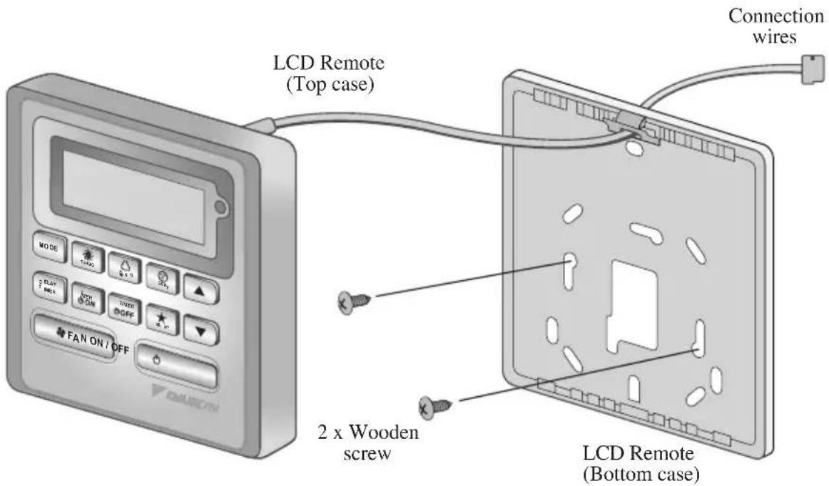
text_image
LCD Remote (Top case) Connection wires 2 x Wooden screw LCD Remote (Bottom case)MEMO
BRC51A61/62 Indication De Contrîleur
text_image
AUTO MON TUE WED THU FRI SAT SUN ALL ON 12 88:88 AM 12 OFF 12 PM DRY AUTO COOL HEAT FAN TURBO QUIET SWING SLEEP SET TEMP. 88 °C MODE TURBO SWING QUIET ▲ DELAY TIMER TIMER ON TIMER OFF SLEEP ▼ FAN ON / OFF 4 5 6 7 12 13 3 2 1 10 9 11 81.10 Bouton ON/OFF (MARCHE'/ARRÊT)
Mise en marche :
RTC: 12:00AM, MONDAY
Oscillation : Arrêt
RTC: 12:00AM, MONDAY
Luftschwenken (Swing): Aus
RTC: 12:00AM, MONDAY
RTC: 12:00AM, MONDAY
Oscilación: Apagado
RTC: 12:00AM, MONDAY
RTC: 12:00AM, MONDAY
Salınım: Kapalı
P.O.Box 18674, Galleries 4, 11th Floor, Downtown Jebel Ali, Dubai, UAE.
DAIKIN INDUSTRIES, LTD.
Head office:
Umeda Center Bldg., 2-4-12, Nakazaki-Nishi, Kita-ku, Osaka, 530-8323 Japan
Tokyo office:
JR Shinagawa East Bldg., 2-18-1, Konan, Minato-ku, Tokyo, 108-0075 Japan http://www.daikin.com/global/
Importer for Turkey
DAIKIN ISITMA ve SOĞUTMA SISTEMLERI SAN TIC A.Ş.
JR Shinagawa East Bldg., 2-18-1, Konan,
Minato-ku, Tokyo, 108-0075 Japan
http://www.daikin.com/global/
DAIKIN EUROPE N.V.
P.O.Box 18674, Galleries 4, 11th Floor,
Downtown Jebel Ali, Dubai, UAE.
Importer for Turkey
DAIKIN ISITMA ve SOĞUTMA SISTEMLERI SAN TIC A.Ş.