ARXP35M5V1B - Air Conditioning DAIKIN - Free user manual and instructions
Find the device manual for free ARXP35M5V1B DAIKIN in PDF.


User questions about ARXP35M5V1B DAIKIN
0 question about this device. Answer the ones you know or ask your own.
Ask a new question about this device
Download the instructions for your Air Conditioning in PDF format for free! Find your manual ARXP35M5V1B - DAIKIN and take your electronic device back in hand. On this page are published all the documents necessary for the use of your device. ARXP35M5V1B by DAIKIN.
USER MANUAL ARXP35M5V1B DAIKIN
text_image
THE KEY FOR SMART INFORMATION Scan and find out moreR32 split series
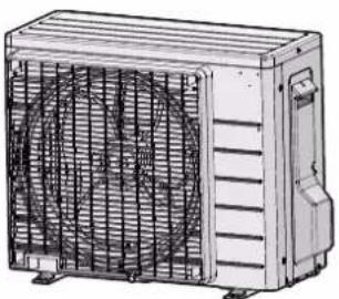
natural_image
Technical line drawing of a large industrial fan or air conditioning unit with visible blades and cooling fins (no text or symbols)RXP20M5V1B
RXP25M5V1B
RXP35M5V1B
ARXP20M5V1B
ARXP25M5V1B
ARXP35M5V1B
Installation manual R32 split series
RXP20M5V1B, RXP25M5V1B, RXP35M5V1B, ARXP20M5V1B, ARXP25M5V1B, ARXP35M5V1B,
| 01 | are in conformity with the following standard(s) or other normative document(s), provided that these are used in accordance with our instructions: | 08 | estão em conformidade com a(s) seguinte(s) norma(s) ou outro(s) documento(s) normativo(s), desde que esles sejam utilizados de acordo com as nossas instruções. | 16 | meglelehek az alaboi szabványtokrak vagy egyeb iranyado dokumentum(cknak, ha azokat előás szernil hasznájak: | 17 |
| 02 | dardan folgancen Komjorn/oder ahem ančaren Nomdkument oder -cokumentan entsorichtentsprachon, unter der Voraussatzung, daß sie gemäß unsaren Anweisungen eingesetzt werden: | 09 | contactsteyot следующим стандартam unii другим нормативным документам, при условим их использования согласно нашим инструкциям: | 17 | spalnajaj kryogni nastojujacych nom i imnyk dokumentiv normazacynych, pod warunkim za używana sa zgodnie z naszymi instrukçani: | 18 |
| 03 | sonri conformes a laux norm(s) ou autre(s) document(s) normat(s), pour autant quils so ent utilis conformément à nos instructions: | 10 | overhöer folgende standard(er) eller andetanore rebringsvende dokument(er), forutsat at disse anvendes i henhold til vore instrukser: | 18 | sunt in conformitate cu umržatoru (urmizotarele) standard(e) sau all(e) document(e) normativ(e), cu conditja ca aceosta sa fie utilizate in conformitate cu instrucjuntile noastre: | 19 |
| 04 | confirm ce voigance norm(er) of één of meer andere bindence documenten zijn op voorwaarde cial ze worden gebruikt overeenkomstig onze instruções: | 11 | respektive utrustring ar utford i övererstaßmelse med och filj főjande standard(er) eller andra normgivande dokument, under forutsättning att användning sker i övererstaßmelsa med vára instruktioner: | 19 | skladi z nasledrijni standard in drugmi normativi, pod popoyem, da sa uporabljao v skladu z našimi navodili: | 20 |
| 05 | están en conformidad con la(s) siguiente(s) norma(s) u otro(s) documento(s) normativo(s), siempre que sean utilizados de acuerdo con nuestras instruções: | 12 | respektive ubtyr er overersteimmelse med folgende standard(er) eller andre normgivende dokument(er), under forutsättning av at disse brukes lhenido til vare instrukser: | 20 | on vastauses ärgmes(y)je standard(tiega või teste normativese documenta dega, kui nald kasutakse vastavell meia juhendtate: | 21 |
| 06 | sono conformi at(i) seguente(i) standard(s) o altro(i) document(i) a carattere normativo, a patio che vengano usati in conformità alle nostre istruzioni; | 13 | vastaval seuravlen standardien ja muiden ohjellsten dokumentien vastimusia edellydan, että nilä käyteliän ohjeldenne mukaisesti: | 21 | scovestctat na cnednite standardini undru normativi pneumytiu, trip uysone ve ce kaupozteat cyšląsno hašinite instrukции: | 22 |
| 07 | ska ovupuva pa to(q) okoubou(a) portuota(s) i dojo tyssop(a) kuvocupauv, untó tvu troočtróšen óni yprouotrotóvtrai | 14 | za predpokladu, że jsou využivany v soulacu s našimi pokyny, odpovicaj nasledujcim normami nebo normativnim dokumentim: | 22 | allinka zerniu nurecylus standardis ir (artea) klius nominimus documentus su salyga, kad yra naudojami pagal műsü, nurodytus: | 23 |
| 08 | oupruva pu te oðnýles pocs: | 15 | u skladu sa sijedećim standardom(irma), il drugim normativnim dokumentom(irma), uz uyet da se oni korste u skladu s našim uputama: | 22 | lad, ja leolii altibisišo ražolja norătjurnem, alorist sekopšiem standardiem un ciliem normativiem dokumentiem: | 24 |
| 09 | following the provisions of: | 16 | Low Voltage 2014/35/EU Electromagnetic Compatibility 2014/30/EU Machinery 2006/42/EC | * | sú v znoce s nasledinovnú(ý)m normoulami aleco irým(í) normativnym(i) dokumentom(ami), za predocklasu. Ze sa použkaju v sülade s našim navodom: | 25 |
| 10 | gemás den Vorschriften der: | 17 | in unna prevederior: | 01 | dréclives, as amended. | 10 |
| 01 | conformément aux stipulations des: | 18 | according to the Certificate | 02 | Direktiver, gemáš Änderung. | 11 |
| 02 | overeenkomstig de beaplingen van: | 19 | glii i herindol it bestemmelsene i: | 03 | Direktives, telles cue modifiées. | 12 |
| 03 | siguendo las disposiciones de: | 20 | noudaltsen määrdysiä: | 04 | Richiljen, zoals geamerdeerd. | 13 |
| 04 | secondo le corso per: | 21 | za dodrženi ustanoveni precosu: | 05 | Oredivas, según lo emrendado. | 14 |
| 05 | pe trponjov tuw čordýciu vru: | 22 | kevěti aizp: | 06 | Oredive, come da modifica. | 15 |
| 06 | de acordo com o previsto em: | 23 | zgodnie z postanowieniam Dyrečiyu: | 07 | Obryčiv, omus ātvov protomaniči: | 16 |
| 07 | B counterfeit stam s положеники: | 24 | in unna prevederior: | 08 | Oredivas, conforme elleração em. | 17 |
| 08 | in unna prevederior: | 25 | in unna prevederior: | 09 | Direktives co osemi popravkami. | 18 |
| 01 | Note* | 06 | ad as set in <A> and judged positively by <B> according to the Certificate | 11 | Information* | 19 |
| 02 | Hinweis* | 07 | wie in <A> aufgelühnt und von <B> positiv beruell gemäß Zertifikat <C>. | 12 | Merk* | 20 |
| 03 | Remarque* | 08 | tel que defini dans <A> et évalué positivement par <B> 08 Nota*conformément au Certificat <C>. | 13 | Huom* | 21 |
| 04 | Bemerik* | 09 | zoals vermaid in <A> an postief ocorbeaid door <B> 09 Примечание*overeenkomstig Certificaat <C>. | 14 | Poznámka* | 22 |
| 05 | Nota* | 10 | como se estabelice en <A> y as valorado positivamente por <B> de acuerdo con el Certificato <C>. | 15 | Napomena* | 23 |
DAIKIN

Table of contents
1 About the documentation 3
1.1 About this document.... 3
2 About the box 3
2.1 Outdoor unit.... 3
2.1.1 To unpack the outdoor unit 3
2.1.2 To remove the accessories from the outdoor unit..... 4
3 Preparation 4
3.1 Preparing the installation site 4
3.1.1 Installation site requirements of the outdoor unit ..... 4
3.1.2 Additional installation site requirements of the outdoor unit in cold climates 4
3.2 Preparing refrigerant piping.... 5
3.2.1 Refrigerant piping requirements.... 5
3.2.2 Refrigerant piping length and height difference ..... 5
3.2.3 Refrigerant piping insulation 5
4 Installation 5
4.1 Opening the units 5
4.1.1 To open the outdoor unit.... 5
4.2 Mounting the outdoor unit.... 5
4.2.1 To provide the installation structure.... 5
4.2.2 To install the outdoor unit....6
4.2.3 To provide drainage....6
4.2.4 To prevent the outdoor unit from falling over 6
4.3 Connecting the refrigerant piping 6
4.3.1 About connecting the refrigerant piping 6
4.3.2 Precautions when connecting the refrigerant piping... 7
4.3.3 To connect the refrigerant piping to the outdoor unit .. 7
4.4 Checking the refrigerant piping 7
4.4.1 To check for leaks....7
4.4.2 To perform vacuum drying....7
4.5 Charging refrigerant .... 7 4.5.1 About charging refrigerant .... 7
4.5.2 About the refrigerant 8
4.5.3 To determine the additional refrigerant amount...... 8
4.5.4 To determine the complete recharge amount.... 8
4.5.5 To charge additional refrigerant.... 8
4.5.6 To fix the fluorinated greenhouse gases label ..... 9
4.6 Connecting the electrical wiring....9
4.6.1 Specifications of standard wiring components..... 9
4.6.2 To connect the electrical wiring on the outdoor unit.... 9
4.7 Finishing the outdoor unit installation 10
4.7.1 To finish the outdoor unit installation 10
4.7.2 To close the outdoor unit 10
5 Commissioning 10
5.1 Checklist before commissioning.... 10
5.2 Checklist during commissioning 10
5.3 To perform a test run.... 10
5.4 Starting up the outdoor unit 10
6 Disposal 11
6.1 Overview: Disposal.... 11
6.2 To pump down.... 11
6.3 To start and stop forced cooling 11
6.3.1 To start/stop forced cooling using the indoor unit ON/OFF switch.... 11
6.3.2 To start/stop forced cooling using the indoor unit user interface 11
7 Technical data 12
7.1 Wiring diagram 12
1 About the documentation
1.1 About this document

INFORMATION
Make sure that the user has the printed documentation and ask him/her to keep it for future reference.
Target audience
Authorised installers
Documentation set
This document is part of a documentation set. The complete set consists of:
- General safety precautions:
- Safety instructions that you MUST read before installing
- Format: Paper (in the box of the outdoor unit)
- Outdoor unit installation manual:
- Installation instructions
- Format: Paper (in the box of the outdoor unit)
- Installer reference guide:
- Preparation of the installation, reference data,...
- Format: Digital files on http://www.daikineurope.com/support-and-manuals/product-information/
Latest revisions of the supplied documentation may be available on the regional Daikin website or via your dealer.
The original documentation is written in English. All other languages are translations.
Technical engineering data
- A subset of the latest technical data is available on the regional Daikin website (publicly accessible).
- The full set of latest technical data is available on the Daikin extranet (authentication required).
2 About the box
2.1 Outdoor unit
2.1.1 To unpack the outdoor unit
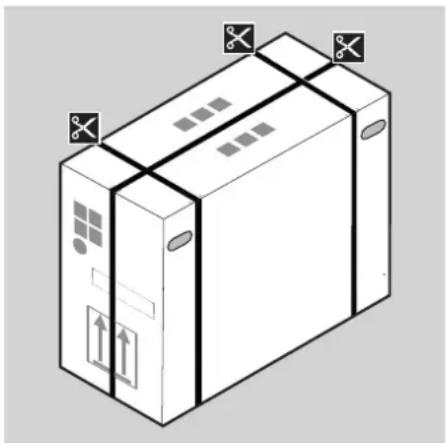
natural_image
Isometric illustration of a cardboard box with visible shipping containers and mounting features (no text or symbols)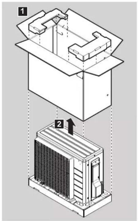
text_image
Technical diagram showing two views of a mechanical or electrical component with numbered annotations and directional arrows.2.1.2 To remove the accessories from the outdoor unit
1 Lift the outdoor unit.
2 Remove the accessories at the bottom of the package.
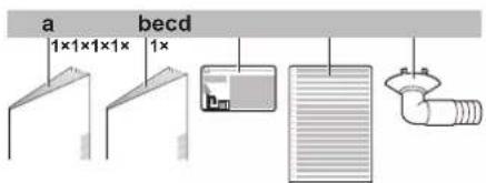
text_image
a 1×1×1×1× 1× becda General safety precautions
b Outdoor unit installation manual
c Fluorinated greenhouse gases label
d Multilingual fluorinated greenhouse gases label
e Drain plug (located on the bottom of the packing case)
3 Preparation
3.1 Preparing the installation site

WARNING
The appliance shall be stored in a room without continuously operating ignition sources (example: open flames, an operating gas appliance or an operating electric heater).
3.1.1 Installation site requirements of the outdoor unit
Mind the following spacing guidelines:
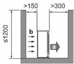
text_image
≤1200 b a >150 >300a Air outlet
b Air inlet
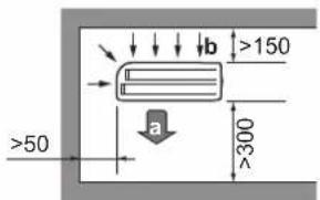
text_image
>b >150 a >50 >300(mm)(mm)
It is recommended to install a baffle plate when the air outlet is exposed to wind.
It is recommended to install the outdoor unit with the air inlet facing the wall and NOT directly exposed to the wind.
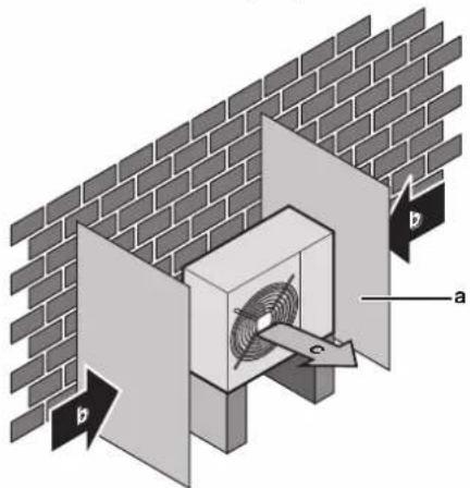
text_image
Technical diagram showing a brick wall with labeled components (a, b) and a coiled component inside a housing.a Baffle plate
b Prevailing wind direction
c Air outlet
3.1.2 Additional installation site requirements of the outdoor unit in cold climates
Protect the outdoor unit against direct snowfall and take care that the outdoor unit is NEVER snowed up.

text_image
Diagram of a brick wall structure with labeled components a, b, c and directional arrows indicating airflow or ventilation.a Snow cover or shed
b Pedestal
c Prevailing wind direction
d Air outlet
In any case, provide at least 300 mm of free space below the unit.
Additionally, make sure the unit is positioned at least 100 mm above the maximum expected level of snow. See "4.2 Mounting the outdoor unit" on page 5 for more details.
In heavy snowfall areas it is very important to select an installation site where the snow will NOT affect the unit. If lateral snowfall is possible, make sure that the heat exchanger coil is NOT affected by the snow. If necessary, install a snow cover or shed and a pedestal.
See also
4.2 Mounting the outdoor unit [▶ 5]
3.2 Preparing refrigerant piping
3.2.1 Refrigerant piping requirements
- Piping material: Phosphoric acid deoxidised seamless copper.
- Piping diameter:
| Liquid piping ∅6.4 mm (1/4") | |
| Gas piping ∅9.5 mm (3/8") |
- Piping temper grade and thickness:
| Outer diameter (∅) | Temper grade Thickness (t) (a) | |
| 6.4 mm (1/4") Annealed (O) ≥0.8 mm |  | |
| 9.5 mm (3/8") Annealed (O) |
(a) Depending on the applicable legislation and the unit's maximum working pressure (see "PS High" on the unit name plate), larger piping thickness might be required.
3.2.2 Refrigerant piping length and height difference
| What? Distance | |
| Maximum allowable pipe length | 15 m |
| Minimum allowable pipe length | 1.5 m |
| Maximum allowable height difference | 12 m |
3.2.3 Refrigerant piping insulation
| Pipe outer diameter ( _p ) | Insulation inner diameter ( _i ) | Insulation thickness (t) |
| 6.4 mm (1/4") | 8~10 mm | ≥10 mm |
| 9.5 mm (3/8") | 12~15 mm |
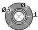
If the temperature is higher than 30^ C and the humidity is higher than RH 80%, the thickness of the insulation materials should be at least 20 mm to prevent condensation on the surface of the insulation.
4 Installation
4.1 Opening the units
4.1.1 To open the outdoor unit

text_image
DANGER: RISK OF ELECTROCUTION DANGER: RISK OF BURNING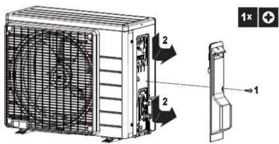
text_image
Technical diagram of an air conditioner unit with labeled components and a 1x magnified view showing part 1.4.2 Mounting the outdoor unit
4.2.1 To provide the installation structure
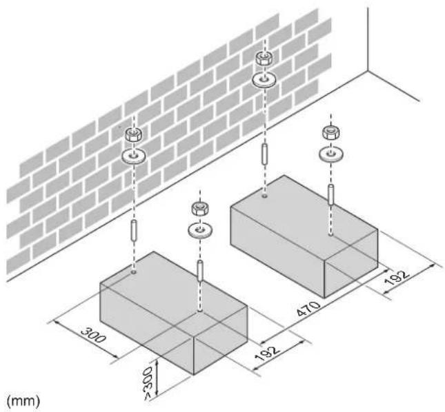
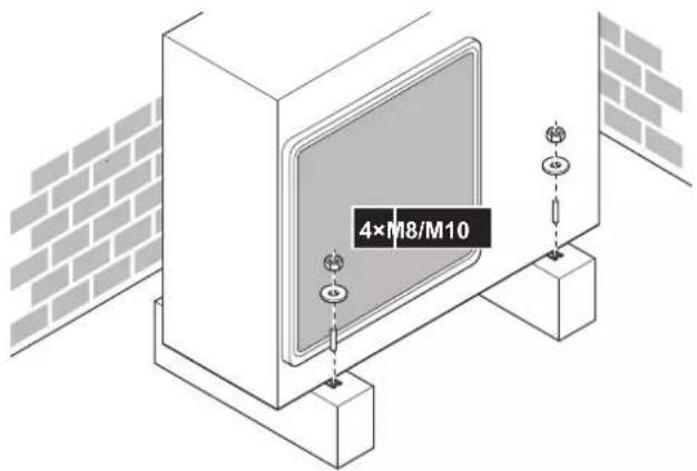
Prepare 4 sets of M8 or M10 anchor bolts, nuts and washers (field supply).
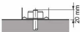
4 Installation
text_image
(mm)In any case, provide at least 300 mm of free space below the unit. Additionally, make sure the unit is positioned at least 100 mm above the maximum expected level of snow. In this case, it is recommended to construct a pedestal.
4.2.2 To install the outdoor unit
text_image
4×M8/M104.2.3 To provide drainage

NOTICE
If the unit is installed in a cold climate, take adequate measures so that the evacuated condensate CANNOT freeze.

INFORMATION
For information on the available options, contact your dealer.

NOTICE
Provide at least 300 mm of free space below the unit. Additionally, make sure the unit is positioned at least 100 mm above the expected level of snow.
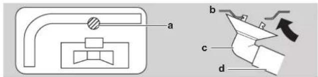
1 Use a drain plug for drainage.
2 Use a ∅16 mm hose (field supply).
text_image
a b c da Drain port
b Bottom frame
c Drain plug
d Hose (field supply)
4.2.4 To prevent the outdoor unit from falling over
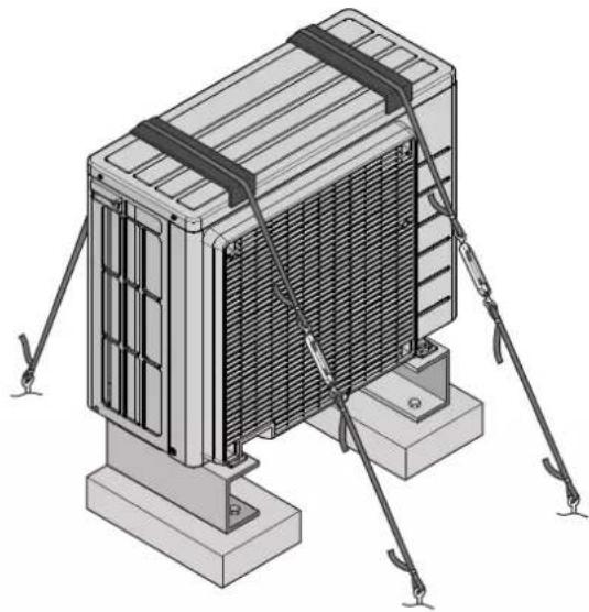
In case the unit is installed in places where strong wind can tilt the unit, take following measure:
1 Prepare 2 cables as indicated in the following illustration (field supply).
2 Place the 2 cables over the outdoor unit.
3 Insert a rubber sheet between the cables and the outdoor unit to prevent the cables from scratching the paint (field supply).
4 Attach the ends of the cables and tighten them.
natural_image
Isometric technical illustration of a heat exchanger or cooling unit with mounting base and support poles (no text or symbols)4.3 Connecting the refrigerant piping

DANGER: RISK OF BURNING
4.3.1 About connecting the refrigerant piping
Before connecting the refrigerant piping
Make sure the outdoor and indoor unit are mounted.
Typical workflow
Connecting the refrigerant piping involves:
- Connecting the refrigerant piping to the indoor unit
- Connecting the refrigerant piping to the outdoor unit
• Insulating the refrigerant piping - Keeping in mind the guidelines for:
- Pipe bending
- Flaring pipe ends
- Using the stop valves
4.3.2 Precautions when connecting the refrigerant piping

DANGER: RISK OF BURNING

CAUTION
- Use the flare nut fixed to the main unit.
- To prevent gas leakage, apply refrigeration oil only to the inside of the flare. Use refrigeration oil for R32.
- Do NOT reuse joints.

WARNING
Connect the refrigerant piping securely before running the compressor. If the refrigerant piping is NOT connected and the stop valve is open when the compressor is run, air will be sucked in. This will cause abnormal pressure in the refrigeration cycle, which may result in equipment damage and even injury.
4.3.3 To connect the refrigerant piping to the outdoor unit
- Piping length. Keep field piping as short as possible.
- Piping protection. Protect the field piping against physical damage.
1 Connect the liquid refrigerant connection from the indoor unit to the liquid stop valve of the outdoor unit.
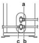
a Liquid stop valve
b Gas stop valve
c Service port
2 Connect the gas refrigerant connection from the indoor unit to the gas stop valve of the outdoor unit.

NOTICE
It is recommended that the refrigerant piping between indoor and outdoor unit is installed in a ducting or the refrigerant piping is wrapped with finishing tape.
4.4 Checking the refrigerant piping
4.4.1 To check for leaks

NOTICE
Do NOT exceed the unit's maximum working pressure (see "PS High" on the unit name plate).

NOTICE
Make sure to use a recommended bubble test solution from your wholesaler. Do not use soap water, which may cause cracking of flare nuts (soap water may contain salt, which absorbs moisture that will freeze when the piping gets cold), and/or lead to corrosion of flared joints (soap water may contain ammonia which causes a corrosive effect between the brass flare nut and the copper flare).
1 Charge the system with nitrogen gas up to a gauge pressure of at least 200 kPa (2 bar). It is recommended to pressurize to 3000 kPa (30 bar) in order to detect small leaks.
2 Check for leaks by applying the bubble test solution to all connections.
3 Discharge all nitrogen gas.
4.4.2 To perform vacuum drying
1 Vacuum the system until the pressure on the manifold indicates -0.1 MPa (-1 bar).
2 Leave as is for 4-5 minutes and check the pressure:
| If the pressure... Then.. | |
| Does not change There is no mo | moisture in the system. This procedure is finished. |
| Increases There is moisture in the system. Go to the next step. | |
3 Vacuum the system for at least 2 hours to a manifold pressure of -0.1 MPa (-1 bar).
4 After turning the pump OFF, check the pressure for at least 1 hour.
5 If you do NOT reach the target vacuum or CANNOT maintain the vacuum for 1 hour, do the following:
- Check for leaks again.
- Perform vacuum drying again.

NOTICE
Make sure to open the stop valves after installing the refrigerant piping and performing vacuum drying. Running the system with the stop valves closed may break the compressor.
4.5 Charging refrigerant
4.5.1 About charging refrigerant
The outdoor unit is factory charged with refrigerant, but in some cases the following might be necessary:
| What | When |
| Charging additional refrigerant | When the total liquid piping length is more than specified (see later). |
| Completely recharging refrigerant | Example: ·When relocating the system. ·After a leak. |
4 Installation
Charging additional refrigerant
Before charging additional refrigerant, make sure the outdoor unit's external refrigerant piping is checked (leak test, vacuum drying).

INFORMATION
Depending on the units and/or the installation conditions, it might be necessary to connect electrical wiring before you can charge refrigerant.
Typical workflow – Charging additional refrigerant typically consists of the following stages:
1 Determining if and how much you have to charge additionally.
2 If necessary, charging additional refrigerant.
3 Filling in the fluorinated greenhouse gases label, and fixing it to the inside of the outdoor unit.
Completely recharging refrigerant
Before completely recharging refrigerant, make sure the following is done:
1 All refrigerant is recovered from the system.
2 The outdoor unit's external refrigerant piping is checked (leak test, vacuum drying).
3 Vacuum drying on the outdoor unit's internal refrigerant piping is performed.

NOTICE
Before completely recharging, perform vacuum drying on the outdoor unit's internal refrigerant piping as well.
Typical workflow – Completely recharging refrigerant typically consists of the following stages:
1 Determining how much refrigerant to charge.
2 Charging refrigerant.
3 Filling in the fluorinated greenhouse gases label, and fixing it to the inside of the outdoor unit.
4.5.2 About the refrigerant
This product contains fluorinated greenhouse gases. Do NOT vent gases into the atmosphere.
Refrigerant type: R32
Global warming potential (GWP) value: 675

NOTICE
In Europe, the greenhouse gas emissions of the total refrigerant charge in the system (expressed as tonnes CO_2 equivalent) is used to determine the maintenance intervals. Follow the applicable legislation.
Formula to calculate the greenhouse gas emissions: GWP value of the refrigerant × Total refrigerant charge [in kg] / 1000
Please contact your installer for more information.

WARNING: FLAMMABLE MATERIAL
The refrigerant inside this unit is mildly flammable.

WARNING
The appliance shall be stored in a room without continuously operating ignition sources (example: open flames, an operating gas appliance or an operating electric heater).

WARNING
- Do NOT pierce or burn refrigerant cycle parts.
- Do NOT use cleaning materials or means to accelerate the defrosting process other than those recommended by the manufacturer.
- Be aware that the refrigerant inside the system is odourless.

WARNING
The refrigerant inside the unit is mildly flammable, but normally does NOT leak. If the refrigerant leaks in the room and comes in contact with fire from a burner, a heater, or a cooker, this may result in fire, or the formation of a harmful gas.
Turn off any combustible heating devices, ventilate the room, and contact the dealer where you purchased the unit.
Do NOT use the unit until a service person confirms that the part from which the refrigerant leaked has been repaired.
4.5.3 To determine the additional refrigerant amount
| If the total liquid piping length is... | Then... |
| ≤10 m Do NOT add additional refrigerant. | |
| >10 m | R=(total length (m) of liquid piping-10 m)×0.020R=Additional charge (kg) (rounded in units of 0.01 kg) |

INFORMATION
Piping length is the one-way length of liquid piping.
4.5.4 To determine the complete recharge amount

INFORMATION
If a complete recharge is necessary, the total refrigerant charge is: the factory refrigerant charge (see unit name plate) + the determined additional amount.
4.5.5 To charge additional refrigerant

WARNING
- Only use R32 as refrigerant. Other substances may cause explosions and accidents.
- R32 contains fluorinated greenhouse gases. Its global warming potential (GWP) value is 675. Do NOT vent these gases into the atmosphere.
- When charging refrigerant, ALWAYS use protective gloves and safety glasses.
Prerequisite: Before charging refrigerant, make sure the refrigerant piping is connected and checked (leak test and vacuum drying).
1 Connect the refrigerant cylinder to the service port.
2 Charge the additional refrigerant amount.
3 Open the gas stop valve.
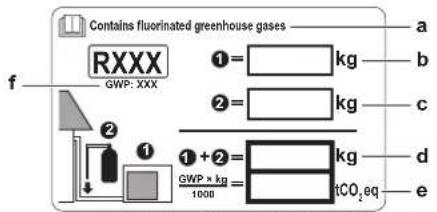
4.5.6 To fix the fluorinated greenhouse gases label
1 Fill in the label as follows:
text_image
Contains fluorinated greenhouse gases RXXX GWP: XXX ①= kg ②= kg ①+②= kg GWP × kg 1000 tCO₂eq a b c d ea If a multilingual fluorinated greenhouse gases label is delivered with the unit (see accessories), peel off the applicable language and stick it on top of a.
b Factory refrigerant charge: see unit name plate
c Additional refrigerant amount charged
d Total refrigerant charge
e Greenhouse gas emissions of the total refrigerant charge expressed as tonnes CO₂ equivalent
f GWP = Global warming potential

NOTICE
In Europe, the greenhouse gas emissions of the total refrigerant charge in the system (expressed as tonnes CO_2 equivalent) is used to determine the maintenance intervals. Follow the applicable legislation.
Formula to calculate the greenhouse gas emissions: GWP value of the refrigerant × Total refrigerant charge [in kg] / 1000
2 Fix the label on the inside of the outdoor unit near the gas and liquid stop valves.
4.6 Connecting the electrical wiring

DANGER: RISK OF ELECTROCUTION

WARNING
- All wiring MUST be performed by an authorised electrician and MUST comply with the applicable legislation.
- Make electrical connections to the fixed wiring.
- All components procured on-site and all electrical construction MUST comply with the applicable legislation.

WARNING
ALWAYS use multicore cable for power supply cables.

WARNING
If the supply cord is damaged, it MUST be replaced by the manufacturer, its service agent or similarly qualified persons in order to avoid a hazard.

WARNING
Do NOT connect the power supply to the indoor unit. This could result in electrical shock or fire.

WARNING
- Do NOT use locally purchased electrical parts inside the product.
- Do NOT branch the power supply for the drain pump, etc. from the terminal block. This could result in electrical shock or fire.

WARNING
Keep the interconnection wiring away from copper pipes without thermal insulation as such pipes will be very hot.
4.6.1 Specifications of standard wiring components
| Component | ||
| Power supply cable | Voltage 220~240 V | |
| Phase 1~ | ||
| Frequency | 50 Hz | |
| Wire sizes | MUST comply with applicable legislation | |
| Interconnection cable (indoor↔outdoor) | 4-core cable ≥1.5 mm ^2 and applicable for 220~240 V | |
| Recommended field fuse | 16 A | |
| Earth leakage circuit breaker | MUST comply with applicable legislation | |
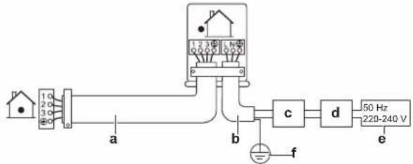
4.6.2 To connect the electrical wiring on the outdoor unit
1 Remove the service cover.
2 Open the wire clamp.
3 Connect the interconnection cable and power supply as follows:
flowchart
graph LR
    A["House"] --> B["1.0"]
    B --> C["2.0"]
    C --> D["3.0"]
    D --> E["+"]
    E --> F[" meters "]
    F --> G["1.325"]
    G --> H["2.5V"]
    H --> I["+"]
    I --> J[" meters "]
    J --> K["1.325"]
    K --> L["2.5V"]
    L --> M["+"]
    M --> N[" meters "]
    N --> O["1.325"]
    O --> P["2.5V"]
    P --> Q["+"]
    Q --> R[" meters "]
    R --> S["1.325"]
    S --> T["2.5V"]
    T --> U["+"]
    U --> V[" meters "]
    V --> W["1.325"]
    W --> X["2.5V"]
    X --> Y["+"]
    Y --> Z[" meters "]
    Z --> AA["1.325"]
    AA --> AB["2.5V"]
    AB --> AC["+"]
    AC --> AD[" meters "]
    AD --> AE["1.325"]
    AE --> AF["2.5V"]
    AF --> AG["+"]
    AG --> AH[" meters "]
    AH --> AI["1.325"]
    AI --> AJ["2.5V"]
    AJ --> AK["+"]
    AK --> AL[" meters "]
    AL --> AM["1.325"]
    AM --> AN["2.5V"]
a Interconnection cable
b Power supply cable
c Circuit breaker
d Earth leakage circuit breaker
e Power supply
f Earth
4 Tighten the terminal screws securely. We recommend using a Phillips screwdriver.
5 Commissioning
4.7 Finishing the outdoor unit installation
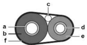
4.7.1 To finish the outdoor unit installation
1 Insulate and fix the refrigerant piping and interconnection cable as follows:
text_image
a b c d e fa Gas pipe
b Gas pipe insulation
c Interconnection cable
d Liquid pipe
e Liquid pipe insulation
f Finishing tape
2 Install the service cover.
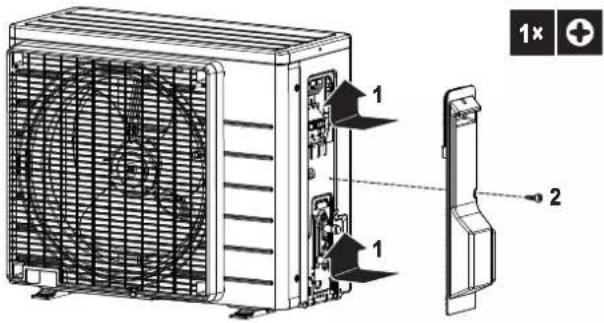
4.7.2 To close the outdoor unit

NOTICE
When closing the outdoor unit cover, make sure that the tightening torque does NOT exceed 1.3 N·m.
text_image
Technical diagram of an air conditioning unit with labeled components and a 1x magnified view indicator.5 Commissioning

NOTICE
NEVER operate the unit without thermistors and/or pressure sensors/switches. Burning of the compressor might result.
5.1 Checklist before commissioning
After the installation of the unit, first check the following items. Once all below checks are fulfilled, the unit MUST be closed, ONLY then can the unit be powered up.
| The indoor unit is properly mounted. | |
| The outdoor unit is properly mounted. | |
| The system is properly earthed and the earth terminals are tightened. | |
| The power supply voltage matches the voltage on the identification label of the unit. | |
| There are NO loose connections or damaged electrical components in the switch box. | |
| There are NO damaged components or squeezed pipes on the inside of the indoor and outdoor units. | |
| There are NO refrigerant leaks. |
| The refrigerant pipes (gas and liquid) are thermally insulated. | |
| The correct pipe size is installed and the pipes are properly insulated. | |
| The stop valves (gas and liquid) on the outdoor unit are fully open. | |
| The following field wiring has been carried out according to this document and the applicable legislation between the outdoor unit and the indoor unit. | |
| DrainageMake sure drainage flows smoothly.Possible consequence: Condensate water might drip. | |
| The indoor unit receives the signals of the user interface. | |
| The specified wires are used for the interconnection cable. | |
| The fuses, circuit breakers, or locally installed protection devices are installed according to this document, and have NOT been bypassed. |
5.2 Checklist during commissioning
| To perform an air purge. | |
| To perform a test run. |
5.3 To perform a test run
Prerequisite: Power supply MUST be in the specified range.
Prerequisite: Test run may be performed in cooling or heating mode.
Prerequisite: Test run should be performed in accordance with the operation manual of the indoor unit to make sure that all functions and parts are working properly.
1 In cooling mode, select the lowest programmable temperature. In heating mode, select the highest programmable temperature. Test run can be disabled if necessary.
2 When the test run is finished, set the temperature to a normal level. In cooling mode: 26\~28°C, in heating mode: 20\~24°C.
3 The system stops operating 3 minutes after the unit is turned OFF.

INFORMATION
- Even if the unit is turned OFF, it consumes electricity.
- When the power turns back on after a power break, the previously selected mode will be resumed.
5.4 Starting up the outdoor unit
See the indoor unit installation manual for configuration and commissioning of the system.
6 Disposal

NOTICE
Do NOT try to dismantle the system yourself: dismantling of the system, treatment of the refrigerant, oil and other parts MUST comply with applicable legislation. Units MUST be treated at a specialised treatment facility for reuse, recycling and recovery.
6.1 Overview: Disposal
Typical workflow
Disposing of the system typically consists of the following stages:
1 Pumping down the system.
2 Bringing the system to a specialized treatment facility.

INFORMATION
For more details, see the service manual.
6.2 To pump down

DANGER: RISK OF EXPLOSION
Pump down – Refrigerant leakage. If you want to pump down the system, and there is a leak in the refrigerant circuit:
- Do NOT use the unit's automatic pump down function, with which you can collect all refrigerant from the system into the outdoor unit. Possible consequence: Self-combustion and explosion of the compressor because of air going into the operating compressor.
- Use a separate recovery system so that the unit's compressor does NOT have to operate.

NOTICE
During pump down operation, stop the compressor before removing the refrigerant piping. If the compressor is still running and the stop valve is open during pump down, air will be sucked into the system. Compressor breakdown or damage to the system can result due to abnormal pressure in the refrigerant cycle.
Pump down operation will extract all refrigerant from the system into the outdoor unit.
1 Remove the valve cap from the liquid stop valve and the gas stop valve.
2 Carry out forced cooling. See "6.3 To start and stop forced cooling" on page 11.
3 After 5 to 10 minutes (after only 1 or 2 minutes in case of very low ambient temperatures ( <-10^ )), close the liquid stop valve with a hexagonal wrench.
4 Check on the manifold if the vacuum is reached.
5 After 2-3 minutes, close the gas stop valve and stop forced cooling.
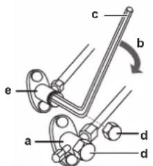
text_image
c b e a d da Gas stop valve
b Closing direction
c Hexagonal wrench
d Valve cap
e Liquid stop valve
6.3 To start and stop forced cooling
There are 2 methods to perform forced cooling.
- Method 1. Using the indoor unit ON/OFF switch (if present on the indoor unit).
- Method 2. Using the indoor unit user interface.
6.3.1 To start/stop forced cooling using the indoor unit ON/OFF switch
1 Press the ON/OFF switch for at least 5 seconds.
Result: Operation will start.

INFORMATION
Forced cooling stops automatically after 15 minutes.
2 To stop operation sooner, press the ON/OFF switch.
6.3.2 To start/stop forced cooling using the indoor unit user interface
1 Set the operation mode to cooling.
For the procedure, refer to "To perform a test run" in the installation manual of the indoor unit.
7 Technical data
A subset of the latest technical data is available on the regional Daikin website (publicly accessible). The full set of latest technical data is available on the Daikin Business Portal (authentication required).
7.1 Wiring diagram
| Unified Wiring Diagram Legend | ||||
| For applied parts and numbering, refer to the wiring diagram on the unit. Part numbering is by Arabic numbers in ascending order for each part and is represented in the overview below by symbol “*” in the part code. | ||||
| CIRCUIT BREAKER | ⊕ | PROTECTIVE EARTH | ||
| CONNECTION | PROTECTIVE EARTH (SCREW) | |||
| CONNECTOR | A | RECTIFIER | ||
| EARTH | RELAY CONNECTOR | |||
| FIELD WIRING | SHORT-CIRCUIT CONNECTOR | |||
| FUSE | TERMINAL | |||
| INDOOR UNIT | TERMINAL STRIP | |||
| OUTDOOR UNIT | ○● | WIRE CLAMP | ||
| BLK : BLACK | GRN : GREEN | PNK : PINK | WHT : WHITE | |
| BLU : BLUE | GRY : GREY | PRP, PPL : PURPLE | YLW : YELLOW | |
| BRN : BROWN | ORG : ORANGE | RED : RED | ||
| A*P | PRINTED CIRCUIT BOARD | PS | SWITCHING POWER SUPPLY | |
| BS* | PUSHBUTTON ON/OFF, OPERATION SWITCH | PTC* | THERMISTOR PTC | |
| BZ, H*O | BUZZER | Q* | INSULATED GATE BIPOLAR TRANSISTOR (IGBT) | |
| C* | CAPACITOR | |||
| AC*, CN*, E*, HA*, HE*, HL*, HN*, HR*, MR*, A, MR*, B, S*, U, V, W, X*A, K*R_* | CONNECTION, CONNECTOR | Q*DI | EARTH LEAK CIRCUIT BREAKER | |
| Q*L | OVERLOAD PROTECTOR | |||
| Q*M | THERMO SWITCH | |||
| D*, V*D | DIODE | R* | RESISTOR | |
| DB* | DIODE BRIDGE | R*T | THERMISTOR | |
| DS* | DIP SWITCH | RC | RECEIVER | |
| E*H | HEATER | S*C | LIMIT SWITCH | |
| F*U, FU* (FOR CHARACTERISTICS, REFER TO PCB INSIDE YOUR UNIT) | FUSE | S*L | FLOAT SWITCH | |
| S*NPH | PRESSURE SENSOR (HIGH) | |||
| FG* | CONNECTOR (FRAME GROUND) | S*NPL | PRESSURE SENSOR (LOW) | |
| H* | HARNESS | S*PH, HPS* | PRESSURE SWITCH (HIGH) | |
| H*P, LED*, V*L | PILOT LAMP, LIGHT EMITTING DIODE | S*PL | PRESSURE SWITCH (LOW) | |
| HAP | LIGHT EMITTING DIODE (SERVICE MONITOR GREEN) | S*T | THERMOSTAT | |
| HIGH VOLTAGE | HIGH VOLTAGE | S*RH | HUMIDITY SENSOR | |
| IES | INTELLIGENT EYE SENSOR | S*W, SW* | OPERATION SWITCH | |
| IPM* | INTELLIGENT POWER MODULE | SA*, F1S | SURGE ARRESTOR | |
| K*R, KCR, KFR, KHuR, K*M | MAGNETIC RELAY | SR*, WLU | SIGNAL RECEIVER | |
| L | LIVE | SS* | SELECTOR SWITCH | |
| L* | COIL | SHEET METAL | TERMINAL STRIP FIXED PLATE | |
| L*R | REACTOR | T*R | TRANSFORMER | |
| M* | STEPPER MOTOR | TC, TRC | TRANSMITTER | |
| M*C | COMPRESSOR MOTOR | V*, R*V | VARISTOR | |
| M*F | FAN MOTOR | V*R | DIODE BRIDGE | |
| M*P | DRAIN PUMP MOTOR | WRC | WIRELESS REMOTE CONTROLLER | |
| M*S | SWING MOTOR | X* | TERMINAL | |
| MR*, MRCW*, MRM*, MRN* | MAGNETIC RELAY | X*M | TERMINAL STRIP (BLOCK) | |
| N | NEUTRAL | Y*E | ELECTRONIC EXPANSION VALVE COIL | |
| n=*, N=* | NUMBER OF PASSES THROUGH FERRITE CORE | Y*R, Y*S | REVERSING SOLENOID VALVE COIL | |
| PAM | PULSE-AMPLITUDE MODULATION | Z*C | FERRITE CORE | |
| PCB* | PRINTED CIRCUIT BOARD | ZF, Z*F | NOISE FILTER | |
| PM* | POWER MODULE | |||
Inhaltsverzeichnis
natural_image
Isometric illustration of a cardboard box with visible internal components and mounting features (no text or symbols)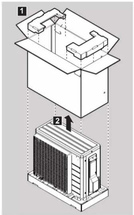
text_image
Technical diagram showing two views of a mechanical or electrical component with numbered annotations and directional arrows.text_image
Diagram showing airflow or ventilation system inside a brick wall, labeled with points a, b, and c.text_image
Diagram of a brick wall structure with labeled components and airflow indicatorstext_image
Technical diagram of an air conditioning unit with labeled components and directional arrows indicating assembly or movement.natural_image
Isometric illustration of a heat exchanger or cooling unit with attached sensors and mounting base (no text or symbols)text_image
Contains fluorinated greenhouse gases RXXX GWP: XXX ①= kg ②= kg ①+ ②= kg GWP × kg 1000 CO₂eq a b c d eGEFAHR: STROMSCHLAGGEFAHR

WARNUNG
text_image
Technical diagram of an air conditioning unit with labeled components and a 1x magnified view5 Inbetriebnahme

HINWEIS
GEFAHR: EXPLOSIONSGEFAHR
natural_image
Isometric illustration of a cardboard box with visible internal components and mounting features (no text or symbols)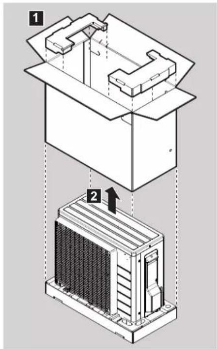
text_image
Technical diagram showing two views of a device with labeled components, including a top view and a side view with an arrow indicating direction.text_image
a 1x1x1x1x becd 1xtext_image
Diagram illustrating airflow or ventilation in a brick wall with labeled components a, b, and ctext_image
Diagram of a brick wall structure with labeled components a, b, and c, showing airflow or ventilation through a pipe.text_image
Technical diagram of an air conditioning unit with labeled components and a 1x magnified view showing part 1.natural_image
Isometric illustration of a heat exchanger or cooling unit with attached sensors and mounting base (no text or symbols)text_image
Technical diagram showing three steps of a server rack installation, labeled 1, 2, and 3 with directional arrows indicating assembly or movement.text_image
Technical diagram showing a brick wall with labeled components and directional arrows, including annotations a, b, and c.text_image
Diagram of a brick wall structure with labeled components a, b, c and directional arrows indicating airflow or ventilation.text_image
Technical diagram of an air conditioning unit with labeled components and directional indicatorsnatural_image
Isometric technical illustration of a heat exchanger or cooling unit with mounting base and support poles (no text or symbols)WAARSCHUWING: ONTVLAMBAAR MATERIAAL
flowchart
graph LR
    A["House 1"] --> B[" meters 1-3"]
    B --> C[" meters 2-3"]
    C --> D[" meters 3-4"]
    D --> E[" meters 4-5"]
    E --> F[" meters 6-7"]
    F --> G[" meters 8-9"]
    G --> H[" meters 10-11"]
    H --> I[" meters 12-13"]
    I --> J[" meters 14-15"]
    J --> K[" meters 16-17"]
    K --> L[" meters 18-19"]
    L --> M[" meters 20-21"]
    M --> N[" meters 22-23"]
    N --> O[" meters 24-25"]
    O --> P[" meters 26-27"]
    P --> Q[" meters 28-29"]
    Q --> R[" meters 30-31"]
    R --> S[" meters 32-33"]
    S --> T[" meters 34-35"]
    T --> U[" meters 36-37"]
    U --> V[" meters 38-39"]
    V --> W[" meters 40-41"]
    W --> X[" meters 42-43"]
    X --> Y[" meters 44-45"]
    Y --> Z[" meters 46-47"]
    Z --> AA[" meters 48-49"]
    AA --> AB[" meters 50-51"]
a Verbindingskabel
b Voedingskabel
c Onderbreker
d Aardlekschakelaar
e Elektrische voeding
f Aarde
text_image
Technical diagram of an air conditioning unit with labeled components and a 1x magnified view showing part 2.5 Inbedrijfstelling

OPMERKING
natural_image
Isometric illustration of a cardboard box with visible internal components and mounting features (no text or symbols)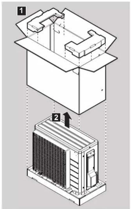
text_image
Technical diagram showing two views of a mechanical or electrical component with numbered annotations and directional arrows.text_image
Technical diagram showing a brick wall with labeled components (a, b, c) and directional arrows indicating flow or movement.text_image
Diagram of a brick wall structure with labeled components and airflow indicatorstext_image
Technical diagram of an air conditioner unit with labeled components and a 1x magnified view showing part 1.natural_image
Isometric illustration of a heat exchanger or cooling unit with attached sensors and mounting base (no text or symbols)text_image
Technical diagram of an air conditioning unit with labeled components and a 1x magnified view5 Puesta en marcha

AVISO
natural_image
Isometric illustration of a cardboard box with visible shipping containers and mounting features (no text or symbols)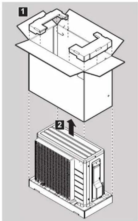
text_image
Technical diagram showing two views of a mechanical or electrical component with numbered annotationstext_image
a 1x1x1x1x becd 1xtext_image
Diagram showing a brick wall with labeled components (a, b, c) and directional arrows indicating movement or force.text_image
Diagram of a brick wall structure with labeled components a, b, and c, showing airflow or ventilation through a pipe.text_image
Technical diagram of an air conditioning unit with labeled components and a close-up view showing part 1 and component 2.text_image
Technical diagram showing a mechanical component with labeled parts a, b, c, d and an arrow indicating direction or force.natural_image
Isometric illustration of a heat exchanger or cooling unit with attached wires and mounting base (no text or symbols)natural_image
Isometric illustration of a cardboard box with visible internal components and mounting features (no text or symbols)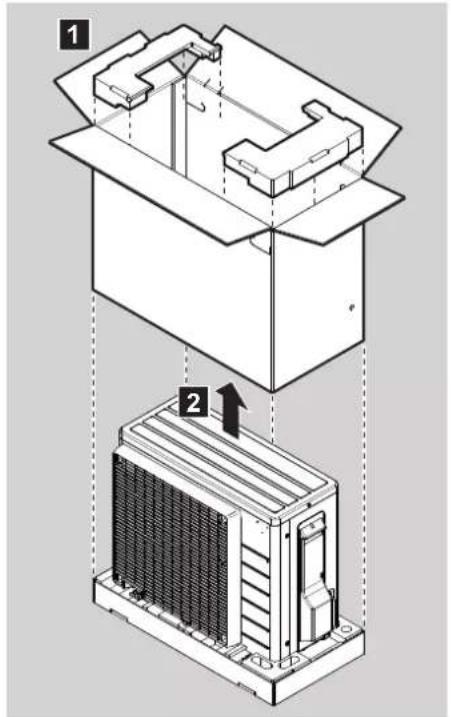
text_image
Technical diagram showing two views of a mechanical or electrical component with numbered annotations and directional arrows.text_image
Technical diagram showing a brick wall with labeled components (a, b, c) and directional arrows indicating flow or movement.text_image
Diagram of a brick wall structure with labeled components a, b, and c indicating different parts of the installation or ventilation system.text_image
Technical diagram of an air conditioning unit with labeled components and a close-up view showing part 1 and component 2.text_image
Technical diagram showing a mechanical assembly with labeled parts a, b, c, and d, including a directional arrow indicating movement.natural_image
Isometric illustration of a heat exchanger or cooling unit with attached wires and mounting base (no text or symbols)natural_image
Isometric illustration of a cardboard box with visible internal components and mounting features (no text or symbols)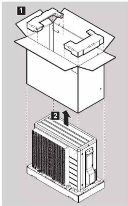
text_image
Technical diagram showing two views of a device with labeled components, including a top view and a side view with an arrow indicating direction.text_image
a 1x1x1x1x becd 1xtext_image
Diagram illustrating airflow or ventilation in a brick wall with labeled components a, b, and ctext_image
Diagram of a brick wall structure with labeled components a, b, and c, showing airflow or ventilation through a pipe.text_image
Technical diagram of an air conditioning unit with labeled components and a close-up view showing part 1 and component 2.text_image
Technical diagram showing a mechanical component with labeled parts a, b, c, d and an arrow indicating direction or force.natural_image
Isometric illustration of a heat exchanger or cooling unit with attached wires and mounting base (no text or symbols)text_image
Technical diagram of an air conditioning unit with labeled components and a 1x magnified view indicator.5 Activação

NOTIFICAÇÃO
natural_image
Isometric illustration of a cardboard box with visible internal components and mounting features (no text or symbols)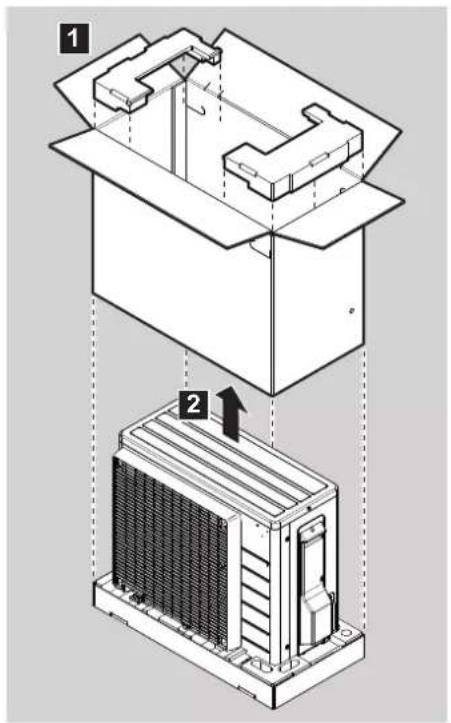
text_image
Technical diagram showing two views of a mechanical or electrical component with labeled parts 1 and 2, indicating assembly or installation.text_image
a 1x1x1x1x 1x becdtext_image
Technical diagram showing a brick wall with labeled components (a, b, c) and directional arrows indicating flow or movement.text_image
Diagram of a brick wall structure with labeled components a, b, c and directional arrows indicating airflow or ventilation.text_image
Technical diagram of an air conditioning unit with labeled components and a close-up view showing part 1 and component 2.natural_image
Isometric technical illustration of a heat exchanger or cooling unit with attached sensors and mounting base (no text or symbols)text_image
Contains fluorinated greenhouse gases RXXX GWP: XXX ①= ②= ①+②= GWPP × kg 1000 a b c d e CO2eqtext_image
Technical diagram of an air conditioning unit with labeled components and a 1x magnified view5 Пусконаладка

ПРИМЕЧАНИЕ
text_image
a 1x1x1x1x becd 1xtext_image
Diagram illustrating a brick wall installation with labeled components a, b, and c, showing a coiled air vent.text_image
Diagram of a brick wall structure with labeled components a, b, and c, showing airflow or ventilation through a pipe.text_image
Technical diagram of an air conditioning unit with labeled components and directional indicatorstext_image
Technical diagram showing a mechanical component with labeled parts a, b, c, d and a tool interacting with a device.natural_image
Isometric technical illustration of a heat exchanger or cooling unit with attached sensors and mounting base (no text or symbols)text_image
Contains fluorinated greenhouse gases RXXX GWP: XXX ①= kg ②= kg ① + ②= GWP × kg 1000 tCO₂eq a b c d enatural_image
Blank grid paper with no text, numbers, or symbols

natural_image
Blank grid paper with no text, numbers, or symbolsDAIKIN ISITMA VE SOĞUTMA SİSTEMLERİ SAN.TİC. A.Ş.
Küçükbakkalköy Mah. Kayışdağı Cad. No: 1 Kat: 21-22 34750 Ataşehir
İSTANBUL / TÜRKİYE
Tel: 0216 453 27 00