
LZV2925SC - Surveillance Camera Lorex - Free user manual and instructions
Find the device manual for free LZV2925SC Lorex in PDF.

| Product Type | PTZ (Pan-Tilt-Zoom) Surveillance Camera |
| Model | Lorex LZV2925SC |
| Resolution | Up to 1080p (1920 x 1080) |
| Sensor | 1/2.8" 2.1 MP |
| Zoom | 25x optical and 16x digital |
| Pan Angle | 360° (continuous) |
| Tilt Angle | -15° to 90° (auto flip) |
| Horizontal Field of View | 59.2° – 2.4° |
| Focal Length | 4.8 ~ 120 mm F1.6 ~ F4.4 |
| Minimum Illumination | 0.01 Lux (color), 0.001 Lux (black and white) |
| Video Formats | CVI, TVI, AHD, SD (CVBS) |
| PTZ Protocol | Pelco-P/D |
| Power Supply | 12 V DC, max 3 A |
| Power Consumption | Max 3 A |
| Connectors | BNC (video), 12 V DC power, RS-485 |
| Weather Rating | IP66 (indoor/outdoor) |
| Operating Temperature | -40 °C to 70 °C |
| Operating Humidity | Up to 90% RH |
| Weight (camera only) | 3 kg (6.6 lb) |
| Weight (with wall mount) | 3.9 kg (8.6 lb) |
| Maintenance and Cleaning | Clean the dome with a damp cloth only. Do not use chemicals (acetone, etc.). |
| Safety | Use the provided safety tether during installation. Mount on a surface capable of supporting the weight. Follow electrical instructions. |
| Spare Parts and Repairability | No user-serviceable parts. Contact qualified technician for repairs. |
| General Information | PTZ camera compatible with Lorex MPX DVRs and analog recorders (CVBS) via RS485. Video format selection via DIP switches. |
Frequently Asked Questions - LZV2925SC Lorex
User questions about LZV2925SC Lorex
0 question about this device. Answer the ones you know or ask your own.
Ask a new question about this device
Download the instructions for your Surveillance Camera in PDF format for free! Find your manual LZV2925SC - Lorex and take your electronic device back in hand. On this page are published all the documents necessary for the use of your device. LZV2925SC by Lorex.
USER MANUAL LZV2925SC Lorex
Instructional Manual LZV2925 1080p MPX PTZ Camera
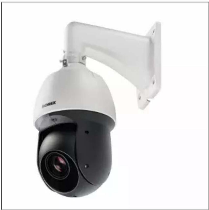
natural_image
Exterior view of a white LOREX security camera with mounted sensor (no text or symbols visible)Thank you for purchasing this product. Lorex Corporation is committed to providing our customers with a high quality, reliable security solution.
This manual refers to the following models:
LZV2925
For the latest online manual, downloads and product updates, and to learn about our complete line of accessory products, please visit our website at:
www.lorextechnology.com
WARNING
RISK OF ELECTRIC SHOCK
DO NOT OPEN
WARNING: TO REDUCE THE RISK OF ELECTRIC SHOCK DO NOT REMOVE COVER. NO USER SERVICEABLE PARTS INSIDE.
REFER SERVICING TO QUALIFIED SERVICE PERSONNEL.
The lightning flash with arrowhead symbol, within an equilateral triangle, is intended to alert the user to the presence of uninsulated "dangerous voltage" within the product's enclosure that may be of sufficient magnitude to constitute a risk of electric shock.
The exclamation point within an equilateral triangle is intended to alert the user to the presence of important operating and maintenance (servicing) instructions in the literature accompanying the appliance.
WARNING: TO PREVENT FIRE OR SHOCK HAZARD, DO NOT EXPOSE THIS UNIT TO RAIN OR MOISTURE.
CAUTION: TO PREVENT ELECTRIC SHOCK, MATCH WIDE BLADE OF THE PLUG TO THE WIDE SLOT AND FULLY INSERT.
Table of contents
1 Safety Instructions . . . . . . . . . . . . . . . . . . . . . . . . . . . . .
2 Getting Started . . . . . . . . . . . . . . . . . . . . . . . . . . . . . .
3 Connecting the Camera . . . . . . . . . . . . . . . . . . . . . . . . . .
3.1 Video Cabling (Professional Installations Only) . . . . . . . . . . . .
3.2 Power Cabling (Professional Installations Only) . . . . . . . . . . . .
4 Installation . . . . . . . . . . . . . . . . . . . . . . . . . . . . . . . . . . . .
4.1 Installation Tips & Warnings . . . . . . . . . . . .
4.2 Installation (Indoor / Outdoor) . . . . . . . . . . . . .
5 Controlling the PTZ Camera with a Lorex MPX DVR
5.1 Controlling a PTZ Camera (Local DVR) . . . . . . . . .
5.2 Advanced PTZ Controls. . . . . . . . . . . . . . .
6 Changing PTZ Protocol and Video Format . . . . . . . . . . . . .
6.1 Connecting the PTZ Camera to an Analog DVR (CVBS) . . . . . . . . .
6.2 Controlling the PTZ Camera with an Analog DVR (CVBS) . . . . . . . . . .
6.3 Changing the Camera's PTZ Protocol Information for Analog DVRs (CVBS)
7 Technical Specifications . . . . . . . . . . . . . . . . . . . . . . . . .
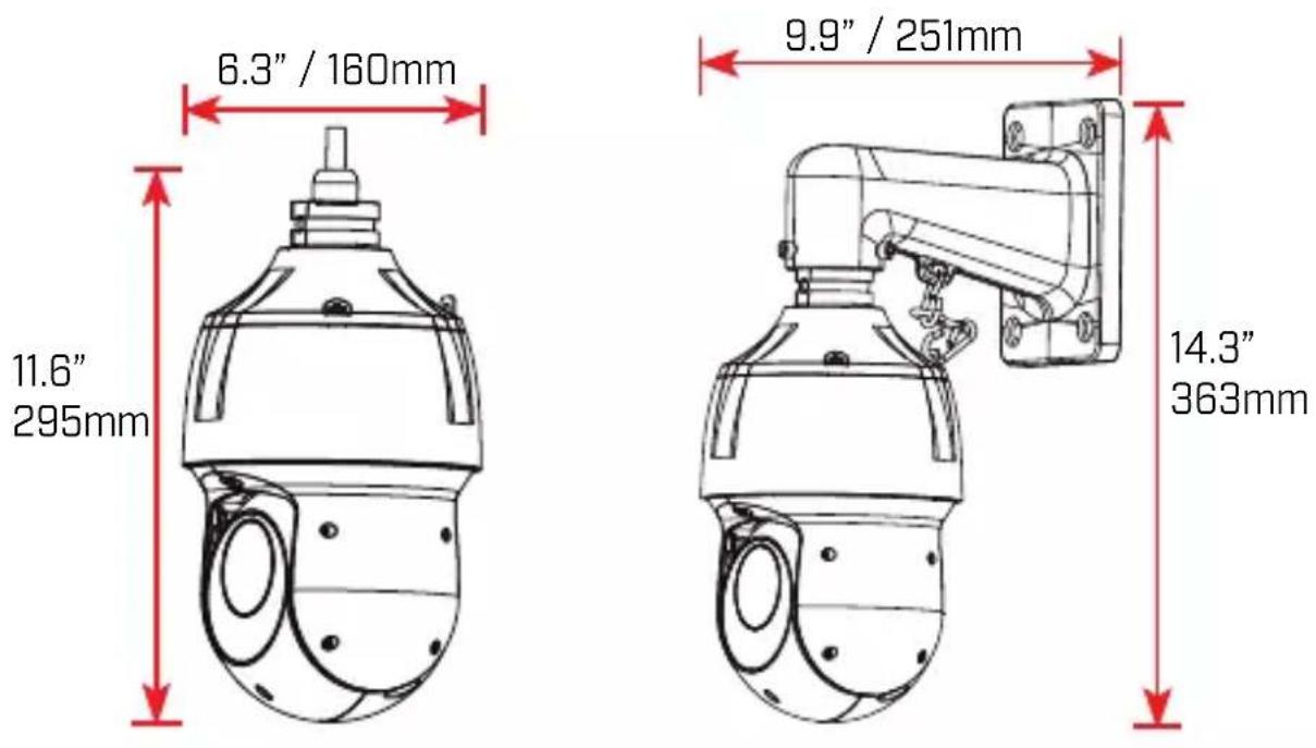
7.1 Dimensions
8 Troubleshooting . . . . . . . . . . . . . . . . . . . . . . . . . . . . . . .
1 Safety Instructions
- Read this guide carefully and keep it for future reference.
- Follow all instructions for safe use of the product and handle with
- Use the camera within given temperature, humidity, and voltage level noted in the Technical Specifications.
- Camera is rated for outdoor use and is weatherproof when properly stalled. Camera is not intended for submersion in water. Installation under a sheltered environment is recommended.
- Do not disassemble the camera.
- Do not point the camera directly towards the sun or a source of light.
- Use only the supplied regulated power supply. Use of a non-regulation non-conforming power supply can damage this product and voids the warranty.
- Make sure to install the camera in a location that can support the weight.
- Make sure there are no live electrical cables in the area where you to mount the camera.
- Periodic cleaning may be required. Use a damp cloth only. Do not anything other than water to clean the dome cover, as chemicals are acetone can permanently damage the plastic.
2 Getting Started
The camera comes with the following components:
 PTZ Camera Wall Mount BNC / Power Extension Cable PTZ Camera Wall Mount BNC / Power Extension Cable | 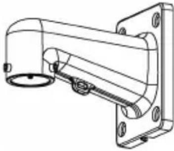 | 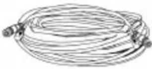 |
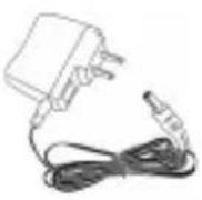 Power Adapter Mounting Screws & Anchors (4x) Power Adapter Mounting Screws & Anchors (4x) | 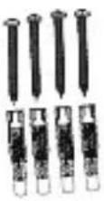 | 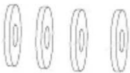 Flat Washers (4x) Flat Washers (4x) |
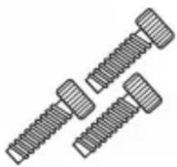 M6x14 Screws (3x) M6x14 Screws (3x) | 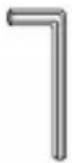 Allen Key Rubber Allen Key Rubber |  Ring Ring |
2 Getting Started
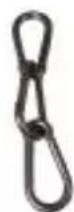
Safety Chain Instruction Manual

NOTE
Your accessories might appear different from the ones depicted in this guide.
3 Connecting the Camera
When you first power up the camera and connect it to the DVR, it is up to two minutes for the camera image to appear.
It is recommended to connect the camera to your DVR and test the controls before permanent installation. For instructions on how to set u PTZ controls, see 5 Controlling the PTZ Camera with a Lorex MPX DVR, page 13.
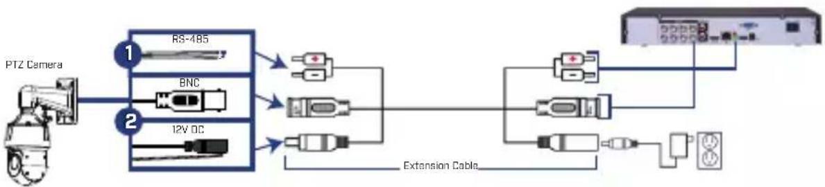
flowchart
graph LR
    A["Camera"] --> B["RS-485"]
    A --> C["BNC"]
    A --> D["12V DC"]
    B --> E["Extension Cable"]
    C --> E
    D --> E
    E --> F["DVR"]
    F --> G["10"]
    F --> H["15"]
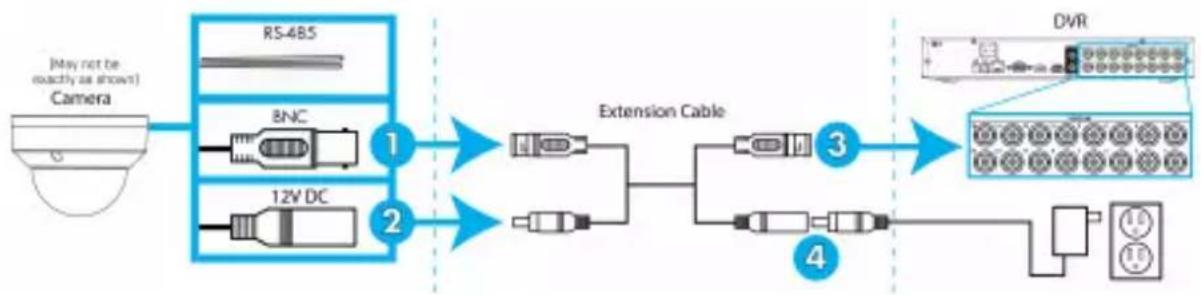
- Connect the BNC video connector on the camera cable to the inc extension cable.
| NOTE |
| The included extension cable is built for this camera a proper video / power connection. |
-
Connect the female 12V DC power connector on the camera cable the male power connector on the included extension cable.
-
Connect the BNC cable on the extension cable to one of the Viput ports on the DVR. Make note of the port number where you nect the camera, as it will be used when configuring the DVR communicate with the camera.
-
Connect the power connector on the extension cable to the include power adapter. Plug the power adapter into a power outlet.
| CAUTION |
| Make sure to disconnect the power adapter before install camera. The camera will begin moving immediately when power adapter is connected. |
- RS485: Only for use with analog DVRs (CVBS) — To control the camera's PTZ functions, connect the camera's RS485 cables to the DVR's RS485 ports. Match the polarity of the RS485 cables with DVR's RS485 positive and negative ports. See 6 Changing PTZ Procol and Video Format, page 21 for full details.
3.1 Video Cabling (Professional Installations Only)
The included extension cable is built for this camera and guarantees J video / power connection. For professional installations only — You can tend the video signal from this camera using a single extension cable between the camera and the DVR. See the table below for the maximum run lengths for all supported cable types:
| Specification Maximum | Length |
| RG59 20AWG Conductor 95% Braid CSA/UL (UL) Approved1 | Up to 985ft (300m)* |
| RG6 20AWG Conductor 95% Braid CSA/UL (UL) Approved1 | Up Go 1640ft (500m)* |
| Analog CCTV Balun Up to 300ft | (91m) |
* Long cable runs over 1000ft may be affected by electro-mechanical ference (EMI), which can increase the amount of noise in the picture some installations.
| NOTE |
| 1. For cable runs above 300ft (91m), you must connect the power adapter directly to the camera, rather than at the extension cable.2. The extension cable must be a single stretch of cable recorder and camera. You cannot connect multiple extens to each other.3. Indicators that your cable run may be too long:Video is permanently black & white (even during dayVideo is unclear, soft, or distorted4. For more information on extension cables, visitwww.lorextechnology.com/support |
3.2 Power Cabling (Professional Installations Only)
See the table below for required cable gauge for longer power cable. For other installations, connect the included 12V DC power adapter due to the camera. Due to voltage drops, it is not recommended to extend cabling beyond 100ft (31m).
| Power Cable Gauge Maximum Length |
| 18AWG Up to 50ft (15m) |
| 17AWG Up to 60ft (18m) |
| 15AWG Up to 100ft (31m) |
4.1 Installation Tips & Warnings

WARNING
Make sure to install the camera in a location that can support the weight.
- Camera is rated for outdoor use. It is recommended to install the in a sheltered area, such as under the eaves on a roof.
- It is recommended to install the camera as high up as possible to best possible image.
- To extend the length of the cable, see 3.1 Video Cabling (Profession Installations Only), page 5.
- Mount the camera where the lens is away from direct and intense sunlight.
- Plan your cable wiring so that it does not interfere with power line telephone lines.
- Ensure you adhere to local building codes.
- Ensure that the camera wiring is not exposed or easily cut.
- Mount the camera in an area that is visible but out of reach.

NOTE
This camera includes all components required for wall mounting.
For the most up-to-date software and complete instruction manuals:
- Visit www.lorextechnology.com.
- Search for the model number of your product.
- Click on your product in the search results.
- Click on the Downloads tab.
4.2 Installation (Indoor / Outdoor)

CAUTION
• Make sure to disconnect the power cable before installing the camera. Camera will begin moving immediately when power cable is connected.
• Make sure to install the camera in a location that can support t camera weight.
To install the camera on a wall:
-
Attach the included rubber ring to the back of the wall mount to the weatherproof rating of the camera.
-
Use the included Allen key to attach the M6x14 screws (3x) to mount. Do not tighten all the way.
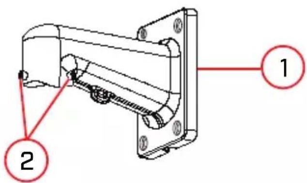
- Wall Mount
-
M6x14 Screws (3x)
-
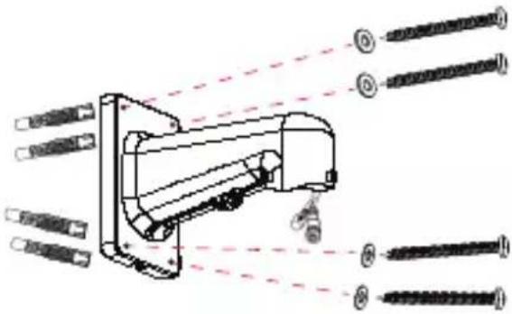
Use the included wall mount to mark holes for the mounting screw (4x) and cables. Drill holes (drill bit size - 3/8") to a depth of 70mm in the mounting surface where marked.
- Insert the included anchors (4x) into the holes and tap them into wall with a hammer.
4 Installation
-
Pull the connection cable(s) through the mounting surface and wall mount.
-
Attach the included flat washers (4x) to the included mounting scr (4x).
-
Firmly attach the wall mount to the mounting surface using the included mounting screws (4x) and flat washers (4x).

WARNING
Make sure to install the wall mount bracket in a location that support the camera's weight. If mounting the camera on a drywa surface, you must drill at least 2 of the mounting screws through wooden stud to ensure a stable mount. See the diagram below details.
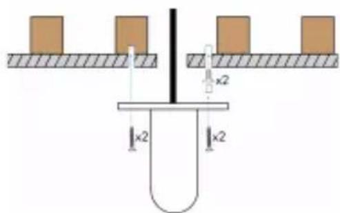
natural_image
Pure mechanical diagram showing a lever and two blocks on a surface, with dimension labels 'x2' (no text or symbols beyond basic geometry)4 Installation
- Connect the safety chain between the camera and the wall mount. allows the camera to hang from the wall mount while connecting cables.
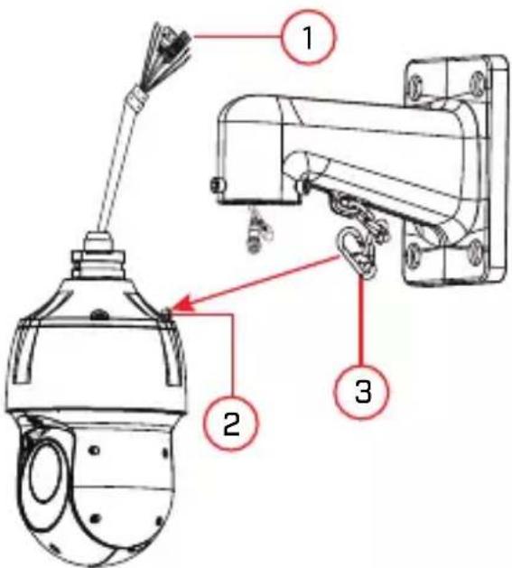
- Camera Cables
- Safety Chain Hook
- Safety Chain
| CAUTION |
| You must connect the safety chain between the camera mount to protect the camera from falling while connecti cables. |
- Connect the connection cable(s) and then push the cable(s) into the wall mount. See 3 Connecting the Camera, page 4 for full details.
4 Installation
- Push the camera into the wall mount with the flat surfaces align the inside. This will allow the M6x14 screw (1) on the wall more align with the hole on the camera.
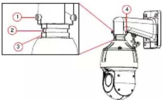
-
M6x14 screw (1) on the flat surface (inside) of the wall mou
-
Hole on the camera.
-
Flat surface on the camera.
-
M6x14 screw (2x).
-
Use the included Allen key to tighten the M6x14 screw (3x) to the camera.
- Remove protective vinyl sheet covering the camera lens once installation is completed.
5 Controlling the PTZ Camera with a Lorex MPX DVR
You can connect the PTZ camera to a Lorex MPX DVR to control era's movement. Lorex MPX PTZ cameras can accept PTZ commands rectly through the coaxial video cable. There is no need to run RS4 wiring to use Lorex MPX PTZ cameras.

NOTE
The following instructions are based on the LHV Series DVRs. See DVR's instruction manual for instructions on controlling the PTZ camera with your system. For the latest list of compatible DVRs, please www.lorextechnology.com/compatibility.
5.1 Controlling a PTZ Camera (Local DVR)
- In Live View, click the channel that has the PTZ camera connect open in full-screen.
- Right-click and click Pan/Tilt/Zoom. Enter the system user name as password if prompted. The PTZ menu opens.
- Use the on-screen PTZ controls to control the camera.
PTZ Controls
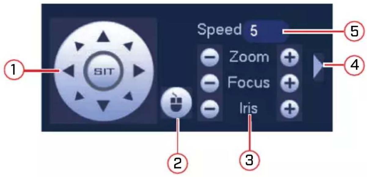
- Direction keys: Click to pan and tilt the camera. Click SIT to stop the current action.
-
Mouse PTZ: Click to activate mouse PTZ mode. In mouse PTZ 1
-
Click and drag to move the camera.
- Use the scroll wheel to zoom in and out.
-
Right-click to exit and return to normal PTZ controls.
-
Zoom/Focus/Iris: Click + / - to adjust the zoom, focus, and iris.
- Advanced controls: Click to open advanced PTZ controls.
- Speed: Enter the PTZ speed from 1 (slowest) to 8 (fastest).
5.2 Advanced PTZ Controls
Advanced PTZ controls can be used to save camera positions and cycle through various positions, and automate camera actions.
To open advanced PTZ controls:
- Click the arrow in the PTZ control window to open advanced con
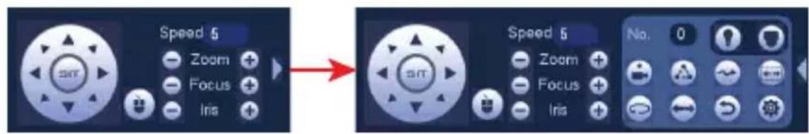
Advanced PTZ controls overview:
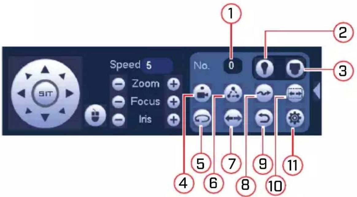
- No.: Select the number of the action you want to perform.
- Not supported.
-
PTZ camera menu: Click to open the camera's OSD menu. This is for advanced users only.
-
Preset: Click to call the selected preset.
- AutoPan: Click to start autopan. During autopan, the camera will tinuously pan 360°. Click again to stop auto pan.
- Tour: Click to run the selected tour.
- Flip: Click to flip the camera 180^ .
- Pattern: Click to run the selected pattern.
- Reset: Click to move the camera to the home position.
- Auto Scan: Click to run the selected autoscan.

- Click to open the PAN/TILT/ZOOM menu, where you can up Presets, Tours, Patterns, and Auto Scans.
5 Controlling the PTZ Camera with a Lorex MPX DVR
5.2.1 Presets
Presets will save a camera position for quick retrieval.
To add presets:
- Click to open the PAN/TILT/ZOOM menu.
- Click the Preset tab.
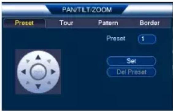
- Enter the number of the preset you want to create under Preset.
- Move the camera to the desired position and click Set.
To go to a preset:
• Under No., select the number of the preset you would like to go

5.2.2 Tours
Tours will cycle through a set of presets.
To create a tour:
- Click to open the PAN/TILT/ZOOM menu.
5 Controlling the PTZ Camera with a Lorex MPX DVR
- Click the Tour tab.
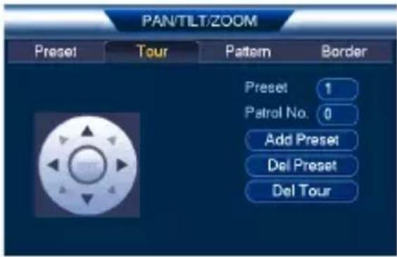
- Under Patrol No., select the tour you would like to configure.
- Under Preset, select a preset you would like to add to the tour.
- Click Add Preset.
- Repeat steps 4 and 5 to add additional presets to the tour.

NOTE
Click Del Tour to clear all presets from a tour.
5 Controlling the PTZ Camera with a Lorex MPX DVR
To run a tour:
• Under No., select the number of the tour you would like to go click.
5.2.3 Pattern
Patterns automatically cycle the camera between two positions.
To create a pattern:
- Click to open the PAN/TILT/ZOOM menu.
- Click the Pattern tab.

- Under Pattern, enter the pattern you would like to configure.
- Move the camera into the desired start position and click Begin.
- Move the camera into the desired end position and click End.
To run a pattern:
• Under No., select the number of the pattern you would like to go click.
5.2.4 Auto Scan
An auto scan automatically cycles between a left and right point.
5 Controlling the PTZ Camera with a Lorex MPX DVR
To create a new auto scan:

-
Click to open the PAN/TILT/ZOOM menu.
-
Click the Border tab.
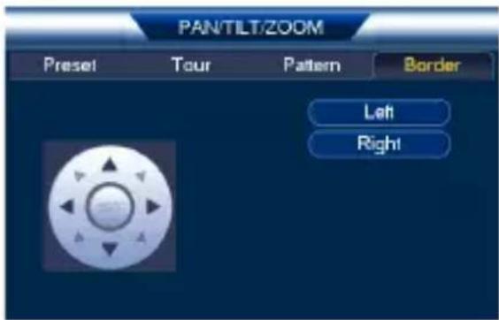
- Move the camera into the desired left position and click Left.
- Move the camera into the desired right position and click Right.
To run an auto scan:

- Click
6 Changing PTZ Protocol and Video Format
The PTZ camera is multi-format, and in addition to Lorex HD DVRs camera will work with recorders that support TVI, AHD, and SD (CV video formats.
6.1 Connecting the PTZ Camera to an Analog DVR (CVBS)
The following diagram shows the full installation of the PTZ camera an analog recorder (CVBS), followed by complete setup instructions.
If you are connecting the PTZ camera to an analog recorder (CVBS), must:
- Run the camera's RS485 cables to the DVR's RS485 ports to con PTZ camera.
- Set the PTZ camera to SD (CVBS) format. For details on changin eo format, see 6.3.4 Switch Between Analog Video Formats, page 26.
flowchart
graph LR
    A["PTZ Camera"] --> B["RS-485"]
    A --> C["BNC"]
    A --> D["12V DC"]
    B --> E["External Connection"]
    C --> E
    D --> E
    E --> F["Extension Cable"]
    F --> G["External Connection"]
    G --> H["PTZ Camera"]

NOTE
The images shown are for illustration purposes only. Components may vary in appearance depending on the model and manufacturer of you DVR. See the instruction manual provided with your security product for full details.
To connect the PTZ camera to an analog DVR (CVBS):
- RS485: Connect the RS485 wires on the camera cable to a pair RS485 communication wires. Connect the other end of the RS485 communication wires into the DVR's RS485 ports. Match the polar of the RS485 cables with the DVR's RS485 positive and negative
| NOTE |
| To extend the PTZ control (RS485) wires beyond 100ft, pair of 24-gauge wires. |
- Connect the power and BNC cables. See 3 Connecting the Camera, page 4 for full connection instructions.
6.2 Controlling the PTZ Camera with an Analog DVR (CVBS)
Once your camera is connected to an analog DVR, you must perform setup to control the camera using the DVR. Once this setup is composed by you will be able to move the camera, configure preset positions, and other advanced controls.
The PTZ camera requires special protocol information to enable an ana DVR to control the camera movement.
Input the following protocol information into your analog DVR's PTZ tings menu to enable the camera's PTZ controls:
- Default Camera ID (Address): 1
- Default Baud Rate: 9600
- Default Parity: None
See your DVR's instruction manual for details.
6.3 Changing the Camera's PTZ Protocol Information for Analog DVRs (CVBS)
Change the default protocol information on your PTZ cameras only with using multiple PTZ cameras or if your DVR does not support the device settings (see your DVR's instruction manual for details).
The PTZ protocol information on this camera is set using DIP switch side the camera. DIP switches represent binary values. This means that are either On (1) or Off (0).
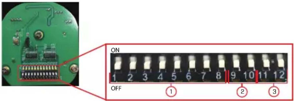
The DIP switches control 3 values:
- Camera ID (Address): The ID of the camera, which allows the D to identify different PTZ cameras. You cannot use the same ID for more than 1 PTZ camera, and you cannot set an ID value of 0.
- Baud Rate: The baud rate, which is the frequency of communicati
- Video Standard: For CVBS recorders, you must set the video stand to SD (CVBS). See 6.3.4 Switch Between Analog Video Formats, page 26 for details.
| NOTE |
| The parity value for this camera is NONE. Parity cann configured. |
6.3.1 Accessing the DIP Switches Inside the Camera
To access the DIP switches inside the camera:
- Loosen the service panel screws (4x), but do not remove them.
- Remove the service panel cover to reveal the DIP switches.
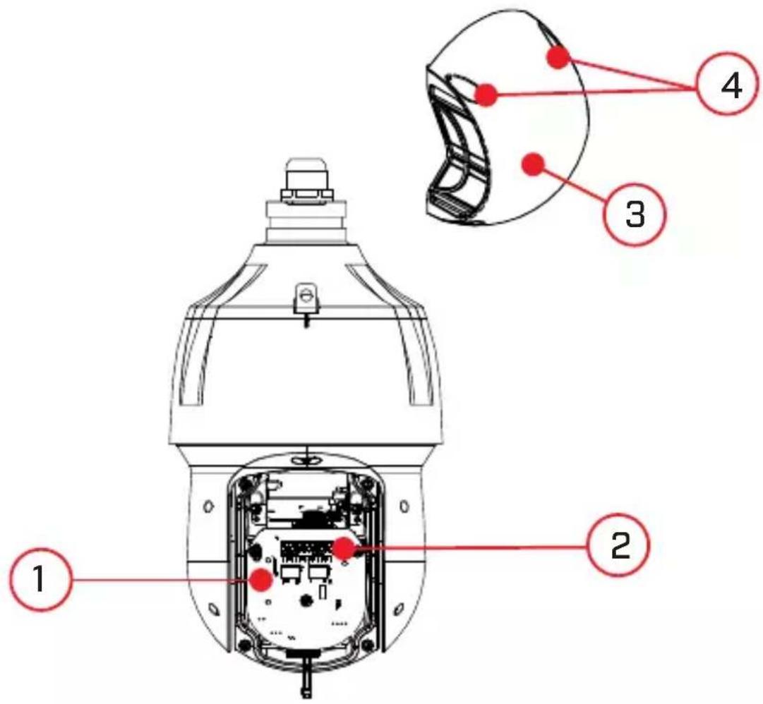
- Service Panel
- DIP Switches
- Service Panel Cover
- Service Panel Screws (4x)
6.3.2 Setting the Camera ID (Address)
The camera ID is how the DVR identifies PTZ cameras. Camera ID using the first 8 switches as show in the above diagram. Each switc sents a binary digit (i.e. switch #1=1, #2=2, #3=3, etc.). Camera ID anything between 1–255. You cannot use the same ID for more than camera, and you cannot set an ID value of 0.

NOTE
By default, the camera ID is set to 1. If you only have you do not need to change the camera ID.
one PT2
| Address (ID) | Switch is ON or OFF | |||||||
| 1 2 | 3 4 5 | 6 7 8 | ||||||
| 1 OFF OF- | F | OFF | OFF | OFF O- | FF | OF-F | OF-F | |
| 1 ON OF- | F | OFF | OFF | OFF O- | FF | OF-F | OF-F | |
| 2 OFF ON OFF | OFF | OFF | OFF | O- | FF | OF-F | OF-F | |
| 3 ON ON OFF | OFF | OFF | OFF | O- | FF | OF-F | OF-F | |
| 4 OFF OF- | F | ON | OFF | OFF O- | FF | OF-F | OF-F | |
| 5 ON OF- | F | ON | OFF | OFF O- | FF | OF-F | OF-F | |
| 6 OFF ON ON | OFF | OFF | OFF | O- | FF | OF-F | OF-F | |
| 7 ON ON ON | OFF | OFF | OFF | O- | FF | OF-F | OF-F | |
| 8 OFF OF- | F | OFF | ON | OFF | O-FF | OFF | OFF | |
| ... | ||||||||
| 254 OFF | ON | ON | ON | ON | ON | ON | ||
| 255 ON | ON | ON | ON | ON | ON | ON | ||
6.3.3 Setting the Camera Baud Rate
Baud rate is set using switches 9 and 10. Parity is defaulted to NC cannot be configured. See the table below.
Baud Rate Switches:
| 9 10 Baud Rate | ||
| OFF | OFF | 9600bps |
| ON | OFF | 4800bps |
| OFF | ON | 2400bps |
| ON | ON | 1200bps |
6.3.4 Switch Between Analog Video Formats
Video format is set using switches 11 and 12. See the table below.
| 11 | 12 Video Format | |
| OFF | OFF | CVI |
| OFF | ON | AHD |
| ON | OFF | TVI |
| ON | ON | SD (CVBS) |
7 Technical Specifications
| Image Sensor 1/2.8" 2.1MP | |
| Video Format NTSC / | PAL |
| Effective Pixels 1920 (H) x 1080 (V) | |
| Resolution Up to 1080p (1920x1080) | |
| Range 360° Pan (Endless); -15 - 90° Tilt (Auto-Flip) | |
| Preset Speed Max 240°/Sec (Pan); Max 200°/Sec (Tilt) | |
| Zoom 25x Optical Zoom & 16x Digital Zoom | |
| Protocol Pelco-P/D | |
| Min. Illumination 0.01 | Lux in Color; 0.001 Lux in Black and White |
| Lens | Auto Focus |
| Focal Length | 4.8~120mm F1.6 ~F4.4 |
| Field of View (Horizontal) | 59.2 - 2.4° |
| Field of View (Diagonal) | 67.5 - 3.2° |
| S / N Ratio | >55dB (AGC Off) |
| Scan System | Progressive |
| Iris | DC Auto Iris w/Hall-effect |
| Termination | BNC Video / 12V DC Power / RS-485 |
| Video Output | CVI / TVI / AHD / SD (CVBS) |
| Power Requirement | 12V DC ±10% |
7 Technical Specifications
| Power Consumption Max. 3A | |
| Operating Temperature Range | -40°F ~ 158°F / -40°C ~ 70°C |
| Operating Humidity Range | Within 90% RH |
| Indoor/Outdoor Both (IP66) | 1 |
| Weight (Camera Alone) | 6.6lbs / 3kg |
| Weight (Camera & Wall Mount) | 8.6lbs / 3.9kg |
7.1 Dimensions
8 Troubleshooting
No image at startup.
- When the camera is first powered on, it performs a startup check. take up to 2 minutes after startup for the camera image to appea
- Check to ensure your camera is properly connected (see 3 Connecti the Camera, page 4) and that the camera is connected to a 12V power supply.
- Connect the power supply to a different outlet.
- If you are using a longer power cable run, ensure you use the p bling gauge for the length of your cable run. See 3.2 Power Cab. (Professional Installations Only), page 7 for full details.
No image or camera image is unclear.
- Dome cover is dirty. Clean the dome cover with a soft, slightly cloth. Do not use anything other than water to clean the dome chemicals such as acetone can permanently damage the plastic.
- Extension cable run may be too long (see 3.1 Video Cabling (Professional Installations Only), page 5 for details).
- If you are using a longer power cable run, ensure you use the p bling gauge for the length of your cable run. See 3.2 Power Cab. (Professional Installations Only), page 7 for full details.
- Voltage may drop over distance and affect image quality. It is recommended to connect the 12V DC power supply directly to the cable.
Image is distorted.
- Image may become unclear when camera is tilted too close to the era base (for example, pointed parallel to the ceiling). Tilt the car using DVR PTZ controls.
PTZ controls are not working or are not working properly.
- Extension cables may be damaged or are not connected properly. C your extension cable run.
- If using an analog recorder (CVBS), make sure to properly connect camera's RS485 cables to the recorder. Also, set the correct PTZ col information such as address, baudrate, and parity in the analog corder (CVBS). See6 Changing PTZ Protocol and Video Format, page 21 for details.
DVR motion detection is constantly triggering.
- Turn off motion detection on the channel the PTZ camera is connected to. DVRs use video motion detection, which means they detect more by looking for changes between frames (images) in the video. If the camera is moving, the DVR will detect this as motion.
Website
www.lorextechnology.com
Copyright
© 2019, Lorex Corporation
All rights reserved worldwide. Names and marks appearing herein are either registered trademarks or trademarks of Lorex Corporation and/or i subsidiaries. All other trademarks, trade names or company names referenced herein are used for identification only and are the property their respective owners.
Legal disclaimer
As our product is subject to continuous improvement, Lorex Corporation subsidiaries reserve the right to modify product design, specifications & prices without notice and without incurring any obligation.E&OE.
Publ. No.: LX400093
Release: 9.0
Commit: 56187
Head: 56210
Language: en-US
natural_image
Exterior view of a white LOREX security camera with mounted sensor (no text or symbols visible)-
Support mural
-
Vis M6 × 14 (× 3)
4 Installation

AVERTISSEMENT
4 Installation
© 2019, Lorex Corporation
natural_image
Exterior view of a white LOREX security camera with mounted sensor (no text or symbols visible)
ADVERTENCIA
4 Instalación
© 2019, Lorex Corporation