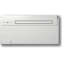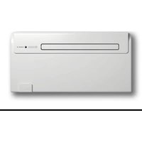
Unico AIR 8 SF - Air Conditioning OLIMPIA SPLENDID - Free user manual and instructions
Find the device manual for free Unico AIR 8 SF OLIMPIA SPLENDID in PDF.


| Product type | Wall-mounted monobloc air conditioner |
| Brand | Olimpia Splendid |
| Model | Unico AIR 8 SF |
| Dimensions (W x H x D) | 980 x 490 x 160 mm |
| Weight (without packaging) | 37 kg |
| Power supply | 230 V ~ 50 Hz |
| Refrigerant gas | R-410A |
| Refrigerant charge | 0.48 kg |
| Main functions | Cooling, dehumidification, ventilation |
| Installation type | Wall-mounted (high or low) |
| Passage hole diameter | 162 mm |
| Minimum distance from floor | 100 mm |
| Minimum distance from ceiling | 80 mm |
| Maximum duct length | 1 m |
| Remote control type | Wireless, with LR03 batteries (not supplied) |
| Air filter | Washable, clean every 2 weeks |
| Condensate drainage | By gravity, minimum slope 3% |
| Compressor protection | 3-minute restart delay |
| Noise level | Not specified (see rating plate) |
| Periodic maintenance | Filter and coil cleaning by technician |
| Safety | Automatic shut-off in case of condensate overflow |
Frequently Asked Questions - Unico AIR 8 SF OLIMPIA SPLENDID
User questions about Unico AIR 8 SF OLIMPIA SPLENDID
0 question about this device. Answer the ones you know or ask your own.
Ask a new question about this device
Download the instructions for your Air Conditioning in PDF format for free! Find your manual Unico AIR 8 SF - OLIMPIA SPLENDID and take your electronic device back in hand. On this page are published all the documents necessary for the use of your device. Unico AIR 8 SF by OLIMPIA SPLENDID.
USER MANUAL Unico AIR 8 SF OLIMPIA SPLENDID
INSTRUCTIONS FOR INSTALLATION, USE AND MAINTENANCE GB
INSTRUCTIONS POUR L'INSTALLATION, L'EMPLOI ET L'ENTRETIEN F
HANDBUCH FÜR INSTALLATION, GEBRAUCH UND WARTUNG D
INSTRUCCIONES PARA LA INSTALLACION, USO Y MANTENIMIENTO E


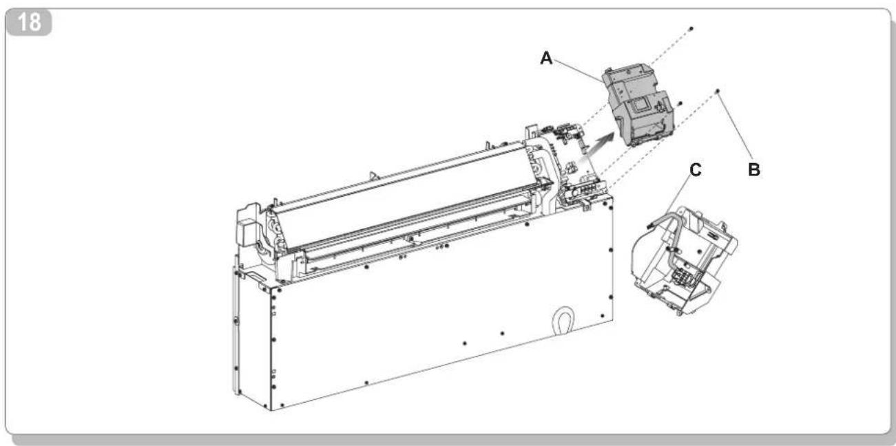
19
20

21
22
23
24
AVVERTENZE
- The appliance may be used by children over 8 years of age and by persons with reduced physical, sensorial or mental capacities, or without the required experience or knowledge, provided they are supervised or have been instructed in the safe use of the appliance and understand the hazards involved.
- Children must not play with the equipment.
- Children must not be allowed to clean the appliance or perform user maintenance without proper supervision.
- If the power cable is damaged, it must be replaced by the manufacturer or by its technical support service or by similarly qualified personnel, to prevent any risk to the user.
- Installation, initial start-up and subsequent maintenance, with the exception of the ambient air filter cleaning and washing, must be carried out solely by authorised and qualified personnel.
- To prevent the risk of an electric shock it is mandatory to switch off the main switch before performing the electrical connections or any maintenance operation to the appliances.
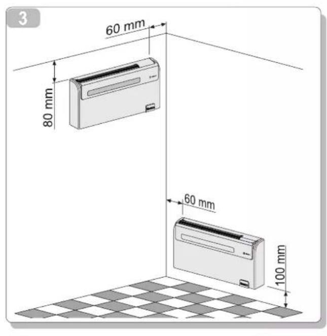
- During installation, comply with the minimum clearances shown in Figure 3
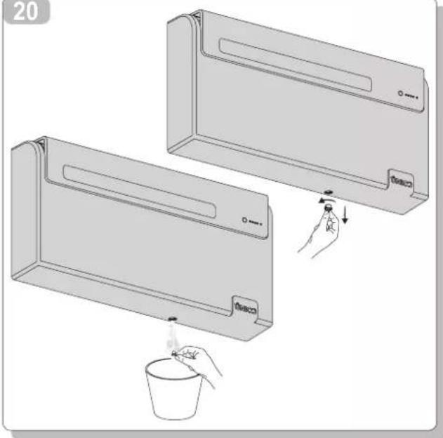
- During the appliance electrical connection, following the indications shown in Fig. 20.
1 GENERAL
1.1 SYMBOLS 26
1.1.1 Editorial pictograms 26
1.1.2 Safety pictograms 26
1.2 GENERAL INFORMATION 26
1.3 27
1.4 LIST OF SUPPLIED COMPONENTS 27
1.4.1 Storage 28
1.4.2 Receipt and unpacking- 28
1.5 UNIT ELEMENTS 28
2 INSTALLATION
2.1 INSTALLATION MODES 29
2.1.1 Size and specifications of the room in which to install the air conditioner 29
2.2 CHOOSING THE POSITION OF THE UNIT 29
2.3 UNIT ASSEMBLY 29
2.3.1 Warning 29
2.3.2 Drilling the wall 29
2.3.3 Preparing the condensate discharge 30
2.3.4 Assembly of the air ducts and external grids 30
2.3.5 Preparing the holes on the machine 31
2.3.6 Fitting the unit on the bracket 31
2.3.7 Electric hook-up 31
2.4 TOP/Bottom INSTALLATION CONFIGURATION 32
2.5 OPERATING TESTS AND TROUBLESHOOTING 32
2.5.1 Evacuating condensate water during an emergency 32
2.6 ROUTINE MAINTENANCE 33
2.6.1 Cleaning the air filter 33
3 USE AND MAINTENANCE (user part)
3.1 34
3.1.1 Description of the warning panel 34
3.2 MANAGING THE UNIT WITH THE REMOTE CONTROL 34
3.2.1 Remote control- 34
3.2.2 Fitting the batteries 34
3.3 REMOTE CONTROL 35
3.3.1 Description of the remote control 35
3.3.2 Main switch-on and running management 35
3.3.3 Turning the unit ON/OFF 35
3.3.4 Well-being key (automatic operating) 35
3.3.5 Cooling 35
3.3.6 Dehumidification only- 36
3.3.7 Ventilation only 36
3.3.8 Heating (only models fitted with heating pump) 36
3.3.9 Air flow direction control 36
3.3.10 Checking fan speed 36
3.3.11 Night well-being key 36
3.3.12 Setting the operating programs 37
3.3.13 Setting the exact time 37
3.3.14 Setting the times of the 1st and 2nd the operating programs (PROGR. 1 and PROGR. 2) 37
3.3.15 Starting and stopping the operating programs 37
3.3.16 Resetting all remote control functions 37
3.3.17 Managing the unit if the remote control is not available 37
3.4 ENERGYSAVING ADVICE 38
3.5 DIAGNOSIS OF THE PROBLEMS 38
3.5.1 Functional aspects not to be interpreted as problems 38
3.5.2 Troubleshooting 38
3.5.3 Specifications 39
1 GENERAL
1.1 SYMBOLS
The pictograms shown in the next chapter provide the information necessary for correct use of the appliance in a rapid and un-mistakable way.
1.1.1 Editorial pictograms

Service
- Refers to situations in which you should inform the SERVICE department in the company: CUSTOMER TECHNICAL SERVICE.

Index
- Paragraphs marked with this symbol contain very important information and recommendations, particularly as regards safety.
Failure to comply with them could result in:
- danger of injury to the operators
- loss of the warranty
- refusal of liability by the manufacturer.

Raised hand
- Refers to actions that absolutely must not be performed.
1.1.2 Safety pictograms

Danger of high voltage
- Signals to the personnel that the operation described could cause electrocution if not performed according to the safety rules.

Generic danger
- Signals to the personnel that the operation described could cause physical injury if not performed according to the safety rules.

Danger from heat
- Signals to the personnel that the operation described could cause burns if not performed according to the safety rules.
1.2 GENERAL INFORMATION
First of all, we would like to thank you for choosing an air-conditioner produced by our company.
We are sure you will be happy with it because it represents the state of the art in home air conditioning technology.
This manual has been compiled with the aim of providing you with all the explanations necessary to manage perfectly your conditioning system.
Therefore, please read the manual carefully before using the equipment.
By following the suggestions contained in this manual, the conditioner that you have purchased will operate without problems giving you optimum room temperatures with minimum energy costs.
The manual is divided into 3 sections or chapters:
CHAP.1 GENERAL INFORMATION
Aimed at the specialised installer and the end user.
It contains information, technical data and important warnings to heed before installing and using the conditioner.
CHAP.2 INSTALLATION
Aimed exclusively at a specialised installer.
It contains all the information necessary for the positioning and mounting of the conditioner in the place where it will be installed. The installation of the conditioner by non-specialised personnel will invalidate the warranty conditions.
CHAP. 3 USE AND MAINTENANCE (user part)
Contains useful information for understanding the use and programming of the conditioner and the most common maintenance interventions.

This is a legally reserved document and the reproduction or transmission to third parties without the explicit authorisation of OLIMPIA SPLENDID is absolutely forbidden.
The appliances could be subject to updating and therefore appear different from the designs contained herein, although this does not in any way invalidate the texts contained in the manual.
Read this manual carefully before performing any operation (installation, maintenance, use) and follow the instructions contained in each chapter.

THE MANUFACTURER IS NOT RESPONSIBLE FOR DAMAGES TO PERSONS OR PROPERTY CAUSED BY FAILURE TO FOLLOW THE INSTRUCTIONS IN THIS MANUAL.
The manufacturer reserves the right to modify at any time its models without changing the fundamental characteristics described in this manual.

The installation and maintenance of air-conditioners like this one may be hazardous as they contain a cooling gas under pressure as well as powered parts.
Therefore, the installation, first startup and subsequent maintenance should be carried out exclusively by authorized, qualified personnel.
Failing to comply with the instructions contained in this manual, and using the unit with temperatures exceeding the permissible temperature range will invalidate the warranty.
Routine maintenance of the filters and general external cleaning can be done by the user as these operations are not difficult or dangerous.
During the assembly and each maintenance operation, always pay attention to the warnings described in this manual and on the labels affixed inside the appliances, and respect anything suggested by common sense and those of the Safety Norms in force in the place of installation.

Always wear gloves and protective goggles when carrying out interventions on the cooling part of the appliance.
Conditioners MUST NEVER be installed in rooms where there is inflammable gas, explosive gas, a high level of humidity (laundry rooms, greenhouses etc), or in rooms where there are other machines that generate a lot of heat.
Should components need replacing, always use OLIMPIA SPLENDID original spare parts.
IMPORTANT!
To avoid any risk of electric shock always remove the master plug from the mains before making any electrical connections or any other maintenance intervention on the appliances.
Make sure that all personnel responsible for transport and installation of the appliance are aware of these instructions.
IMPORTANT!
Do not allow R-410A to escape into the atmosphere: R-410A is a fluorinated greenhouse gas, as cited in the Kyoto Protocol, with a Potential Global Warming effect (GWP) = 2088.
DISPOSAL
The symbol on the product or on the packaging indicates that the product must not be considered as normal domestic refuse but it must be taken to an appropriate disposal point for recycling electrical and electronic appliances.
Disposing of this product in the appropriate way avoids causing potentially negative consequences both for the environment and for the health that could occur if the product is not disposed of correctly.
Further information about the recycling of this product can be obtained from your local town hall, your refuse collection service, or in the store at which you bought the product.
This regulation is valid only in EU member states.
1.3 WARNING
The air-conditioner should be used for the exclusive purpose of producing hot or cool air (on demand) for the sole purpose of obtaining a comfortable temperature in the room.
Improper use of the equipment, which may cause injury/damage to persons, property or animals, relieves OLIMPIA SPLENDID of any liability.
1.4 LIST OF SUPPLIED COMPONENTS
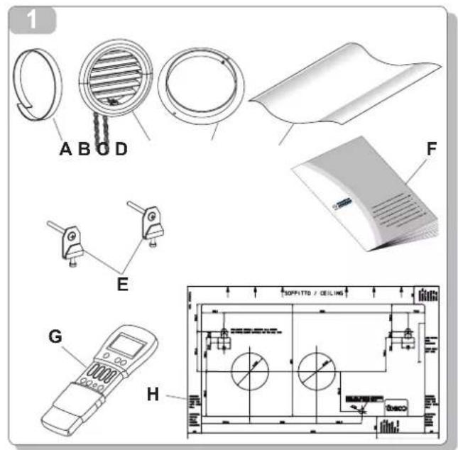
The supply includes the parts listed in the table below (fig. 1). Before beginning to assemble the unit, make sure all the parts are within easy reach.
A - Strip of adhesive isolating tape (n.2)
B - Air inlet and outlet external grid including chains and kit for installing the grids (n.2)
C - Internal flanges (2)
D - Sheet for wall pipes (n.2)
E - Wall anchoring Hooks
F - Use and maintenance booklets + warranty
G - Remote control
H - Paper template to make holes
1.4.1 Storage
Store the packages in a closed room, protected from atmospheric agents and resting on pallets or beams to isolate from the ground.

DO NOT OVERTURN THE PACKAGE.
1.4.2 Receipt and unpacking
The products are packaged by expert personnel using suitable packaging material.
The units are delivered complete and in perfect condition, however we suggest that you perform the following controls of the quality of the shipping service:
on receiving the goods, check if the package is damaged. If affirmative, accept the goods with reserve, taking photographs of any apparent damage.
- unpack and check the contents against the packing list.
- check that none of the components have been damaged during transport; if they have, inform the forwarder by registered letter with receipt within 3 days of receipt of the goods and enclosing photographic evidence.
Send the same information by fax to OLIMPIA SPLENDID
No complaints will be accepted if made more than 3 days after the delivery of the goods.

Important note:
Keep the packaging at least during the warranty period for any possible delivery of the product to a service centre.
Dispos of the packaging in compliance with the regulations concerning refuse disposal.
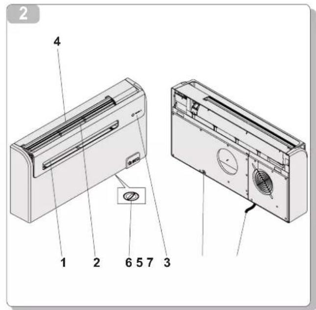
1.5 UNIT ELEMENTS (fig. 2)
The two units that make up the air-conditioner are packed separately in cartons.
Packaging may be transported per single units, by hand by two authorized persons, or loaded on a trolley, even piling up to a maximum of three packs.
1) Air outlet flap
2) Aspiration grill
3) Function and alarms display console
4) Air filters
5) Condensate discharge
6) Emergency condensate discharge
7) Power cable
2 INSTALLATION
2.1 INSTALLATION MODES
To obtain the best results and optimum performance, follow the instructions for correct installation provided in this manual. Failure to follow the instructions and apply the rules indicated may cause malfunction of the appliance and relieves the manufacturer, OLIMPIA SPLENDID of any form of guarantee and liability for damages to persons, animals or property.

The electrical system must comply with the regulations and rating data in the technical sheet, with good grounding.
2.1.1 Size and specifications of the room in which to install the air conditioner
Before installing the air conditioner, it is essential to make an accurate calculation of the heat load in summer (and cold load in winter for models with heating pump) at the site of installation.
The more accurate this calculation is made the better the air conditioner will be able to do its job.
When executing the calculations, refer directly to the prevailing standards.
For particularly important applications, we recommend contacting expert heating engineers.
The user should try to limit high heat loads as much as possible as follows: glass doors and windows exposed to many hours of sunlight should be fitted on the inside with curtains or, even better, on the outside with coverings such as Venetian blinds, verandahs, refractive film, etc.). The air-conditioned room must remain closed as long as possible.
Halogen spotlgs or other electrical equipment with high power consumption should not be used in the room (toasters, steam irons, hot plates for cooking, etc.).
2.2 CHOOSING THE POSITION OF THE UNIT
The position for installing the unit, to obtain best performance and avoid breakdowns or hazards, must have the following requisites (fig. 3):
The height of the unit's lower edge from the floor should be at least 100mm if fixed to the wall in the lowest position.
- If fixed to the wall in the highest position, it should be at least 80mm from the ceiling.
- The wall on which the inside unit is installed must be sturdy and able to withstand its weight.
- It must be possible to leave room around the unit for any maintenance operations that may be necessary.
Nothing should be in the way of the air that needs to circulate both on the top air-intake (curtains, plants, furniture) and at the front where the air exits. This could cause air swirls that would inhibit the working efficiency of the unit.

The air conditioner must be installed on a wall that communicates with the outside.

CAUTION: after determining the best place for installation as described above, check for the absence of other structures or systems (beams, piers, pipes, wires, etc.) at the points where the holes are to be drilled, which would prevent drilling the holes required to install the unit.
Check again to make sure there are no obstacles to air circulation through the holes to be drilled due to plants and their leaves, slats or panelling, blinds, gratings or grids too dense, etc.).

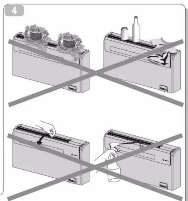
WARNING (fig. 4):
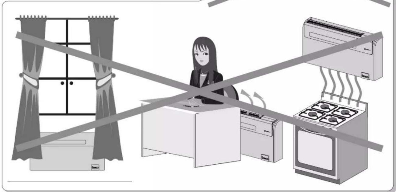
- it should not be placed under curtains;
- do not spray water or other liquids of any kind directly on the unit;
- it should not be installed in a position where the air flow can directly strike people in the whereabouts.
- never force the opening of the airflow flap;
- do not place bottles, cans, clothing, flowers or any other object that may damage the internal organs on the air aspiration grill or anything that may even partially obstruct the grill itself;
it should not be directly over another appliance (television set, radio, refrigerator, etc.), or over a source of heat.
2.3 UNIT ASSEMBLY
2.3.1 Warning
The maximum length allowed for pipes is 1m . The pipes must be smooth on the inside. Pipes cannot be curved or bent. It is necessary to use the grilles provided, or grilles which keep the same features.
2.3.2 Drilling the wall
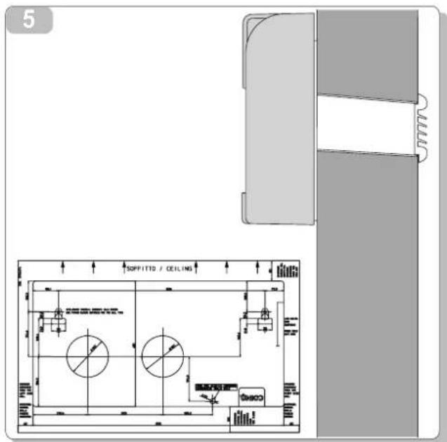
Install the unit by drilling two holes diameter either 162mm in the wall as indicated in the drilling template. The UNICO unit may be installed in lieu of a UNICO unit without changing the position of the existing holes, with the exception of the small hole for condensate drainage. In this case, in order not to penalize performance, remove the insulating material from the air outlet pipe. Drill the wall using the proper tools to facilitate your job and prevent excess damage or disturbance to your client. The best tools for drilling large holes in walls are special drills called core borers with very high twisting torque and adjustable rotating speed depending on the diameter of the hole to be drilled.
To prevent the creation of large amounts of dust and rubble due to drilling, the core borer can be fitted with a vacuum system applied by means of suction cups to the drilling zone.
To drill the holes, proceed as follows:
Fasten the drilling template to the wall leaving the necessary space from the ceiling, floor and side walls as shown on the template that may be fixed using adhesive tape.
Use a small drill or punch to mark, with extreme care, the exact centre of each of the holes to be drilled.
Using a core boring head measuring at least 162mm to drill the two holes for entry and exit of the air.

WARNING: drill the foregoing holes tilted slightly downwards to prevent water from being fed back through the ducts (fig. 5).
Most of the removed material is expelled outwards, therefore make sure that it does not hit any person or object when it falls out. In order to avoid as much as possible outer plaster breaking, it is necessary to proceed carefully with the last part of hole execution, decreasing pressure on core borers.
Next, drill the holes for anchoring the fastening brackets to the wall using as a first option the 4 holes on the ends of the bracket as shown on the drilling template.
If the wall is not very solid, it is advisable to use some extra anchor bolts.
As you can see, the bracket can be fastened in a number of different ways and positions. The majority of the weight of the appliance is to the right side so ensure that fixing is more secure on this side. The anchor bolts provided require holes with a diameter of 10mm .
In any case, the wall should be inspected carefully to determine the best possible anchorage and type of bolts suitable for particular situations.

WARNING: the manufacturer will not be held liable for any underestimates made in the structural consistency of the anchor prepared by the installer.
Therefore, pay utmost attention to the foregoing operation that could cause serious injury/damage to people/property if carried out incorrectly.
When installing models equipped with heating pump, if no condensate discharge was built into the wall (see paragraph 2.3.2), in order to drain the condensate it will be necessary to drill a hole through the wall in the position shown on the template.
2.3.3 Preparing the condensate discharge
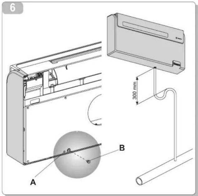
As far as machines equipped with a heating pump are concerned, connect the unit to the condensate discharge pipe (supplied) by coupling it with the specific vent (fig. 6 ref. A) that is on the back of the machine (remove cap B). When the max level is reached, a solenoid valve ensures the condensate will flow out from the internal tray. For cold-only machines, connect the condensate discharge pipe if you intend running the unit at low outdoor temperatures (lower than 23^ ).
Since condensate drains by gravity, there must be a minimum slope of at least 3% at every point of the discharge line. Use a rigid or flexible tube having an inside diameter of at least 16mm .
If the line empties into a sewerage system, install a siphon before the point in which the pipe reaches the main discharge, at least 300mm below the inlet from the unit (fig. 6).

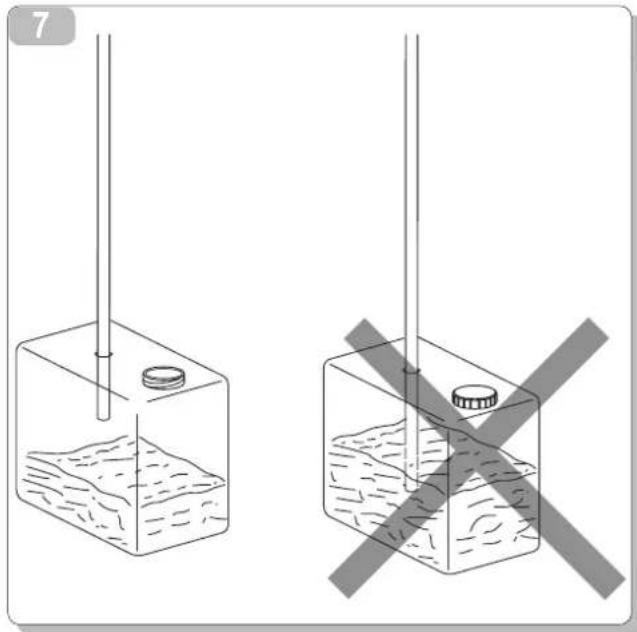
If the drainpipe drains into a vessel (tank or other container), this container should not be sealed and the drainpipe should not remain immersed in the water (see fig. 7).
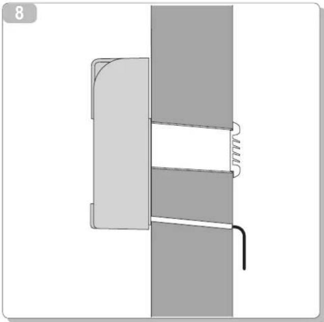
The hole through which the condensate pipe passes should always slope towards the outside (see fig. 8).
The exact position in which to place the pipe inlet, as compared to the machine, is shown on the drilling template.

CAUTION: make sure, in this case, that the water expelled outward does not damage or disturb persons or property. During the winter this type of drainage may cause sheets of ice to form.
When the condensate drainage is fitted, pay much attention not to compress the rubber hose.
2.3.4 Assembly of the air ducts and external grids
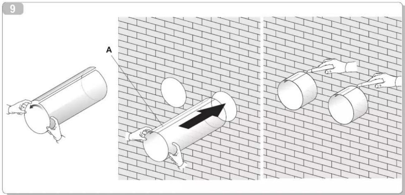
After having drilled the holes, insert the plastic sheet supplied with the conditioner into them.
The length of the sheets must be 65mm less than the thickness of the wall.
Roll the sheet and insert it into the hole (fig. 9), paying attention to the splicing line (fig. 9 ref. A), which must always face upwards.
Use an ordinary cutter for the foregoing operation (fig. 9).
To position the external grids, proceed as follows:
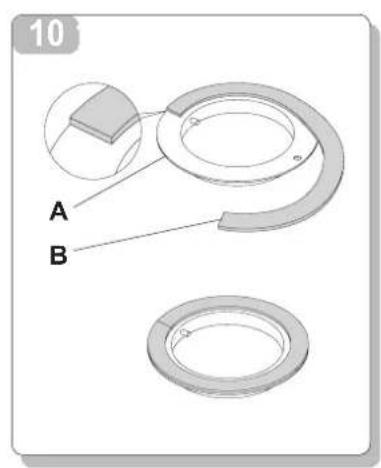
Apply the seal (fig. 10 ref. B) to the wall flange (fig. 10 ref. A), ensuring it lines up with the outer edge of the flange as indicated in the figure.
Fix the two flanges using 2 pegs having a diameter of 6 and check that the two fixing holes are horizontal.
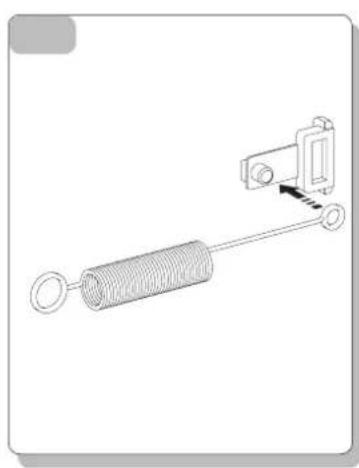
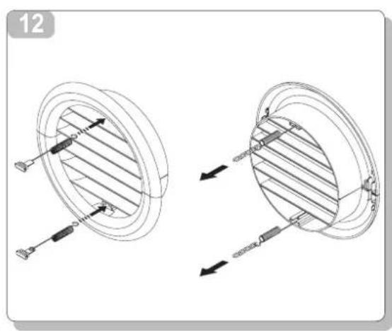
- Fit the small eyelet of the spring, with the long stem, on the cap pin (on both components) (fig. 11).
Insert the two caps (with spring), on the front part of the external grid, on its two housings, pulling until it clicks (fig. 12) and
couple the two chains to the large eyelet of the spring.
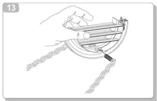
- Using one hand, grip the two chains connected to the grid.
Bend the external grids back, gripping them with your free hand where they bend, and insert your fingers inside the single fins (fig. 13).
- Insert your arm into the pipe until the grid protrudes completely outwards.
- Reopen the grid, being careful to keep your fingers inside the fins.
- Turn the grid until the fins are fully horizontal and tilted downwards.
Pull the chain, tensioning the spring, and couple the chain ring to the pin of the inner flange through which the pipes pass (fig 14).
- Use hand shears to cut off any excess chain links.

WARNING: use exclusively the supplied grids, or grids with like characteristics.
2.3.5 Preparing the holes on the machine
The unit was built to be paired with 162-mm.
2.3.6 Fitting the unit on the bracket
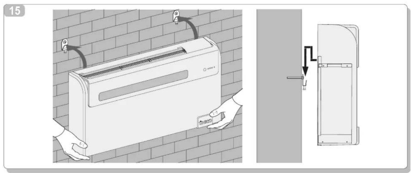
After having checked that the fixing bracket is properly anchored to the wall and that the suitable preparatory work - if required - has been carried out for the electrical connections and the condensate drainage, the air-conditioner can be fixed to the wall. Lift it by holding it from the sides of the lower base (see fig. 15).
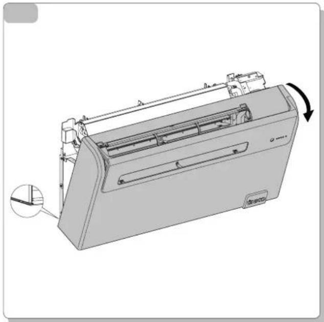
To facilitate the operation of fastening it to the bracket, tilt it slightly toward you.
To make the electrical connection and fasten the drainpipe, place a wedge between the air conditioner and the wall (see fig. 15).
When you have finished, inspect carefully to make sure there are no fissures at the back of the air conditioner (the insulating gasket must fit firmly against the wall) particularly in the zone where air enters and leaves the machine.
2.3.7 Electric hook-up
The appliance is fitted with a power cord with plug (Y-type connection). If the socket is in proximity to the appliance, simply plug it in.

Before connecting the conditioner, ensure that:
- The power supply voltage and frequency values comply with those indicated on the data plate of the appliance.
The power supply line is fitted with an efficient earth connection that is appropriately sized for the maximum absorption of the conditioner (minimum cross-section of the cable must be 1.5mm 2). - The appliance is powered exclusively through a socket that is compatible with the plug supplied.

WARNING: Any replacement of the power cable must be carried out solely by Olimpi Splendid technical support or by similarly qualified personnel.

WARNING: On the power supply line of the appliance there must be an adequate omnipolar disconnection device that complies with the national installation regulations. It is, however, necessary to check that the electrical power supply is equipped with efficient earthing and with adequate protections against overloading and/or short circuits (a type 10 AT delayed fuse or other devices with equivalent functions are recommended).
2.4 TOP/Bottom INSTALLATION CONFIGURATION
This unit may be installed either at the bottom of the wall (adjacent to the floor) or at the top (adjacent to the ceiling). The air jet can be modified to optimize air distribution and room well-being by changing the position of the air outlet flap.
2.5 OPERATING TESTS AND ANOMALY DIAGNOSIS
The conditioner is able to perform a brief auto-diagnosis cycle to check that the internal components are operating normally and during which it is possible to perform the configuration of the electronic control based on whether installation of the appliance was performed to the upper part (to the ceiling) or lower part (to the ground) of the wall.
To activate the self-diagnosis function, proceed as follows:
- power the appliance by connecting it to a socket or by acting on the master switch of the system;
- ensure that the machine is on stand-by (no LED should be lit on the console);
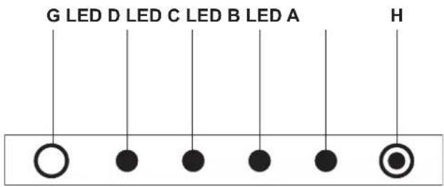
Press the micro-key positioned underneath the hole to the left side of the console (fig. 19 ref. H) with a pointy object for at least 10 seconds. The acoustic signal emitted indicates that the self-diagnosis function has been activated.
At this point the current configuration of the machine will be displayed for a few moments as indicated below:
LED A (red) on: appliance fitted with heat pump function;
LED B (green) on: installation to the lower part of the wall (to the ground) (factory installation);
LED C (orange) on: installation to the upper part of the wall (to the ceiling);
LED D (green) on: reset settings function after an active black-out (factory setting).
Then, all of the LEDs on the console will start flashing simultaneously for 10 seconds. During this phase, through the micro key (fig. 19 ref. H), it is possible to modify the previously displayed setting related to the type of appliance installation.
NB: Configuration of the electronic control for installation to the upper part of the wall determines an automatic correction of the room temperature detected of 3^ .
At this point the self-diagnostic function activates the appliance in heating mode (if fitted with the heat pump function) for approx.2 minutes and then in cooling mode for another 2 minutes.
It is possible to terminate the function prematurely simply by switching the appliance off using the remote control.
Should the conditioner block and signal an error (as indicated in the following table), specify the LEDs that are flashing to the service centre in order to facilitate the intervention (fig. 19).
DESCRIPTION LED D LED C LED B LED A
| GREEN YELLOW GREEN RED | ||||
| Overtemperature of internal exchanger (HTI) | OFF | OFF | ON | OFF |
| Overtemperature of external exchanger (HTE) | OFF | OFF | ON | ON |
| External temperature probe fault (short circuit) (TFS7) | OFF | ON | OFF | OFF |
| External temperature probe fault (open circuit) (TFS8) | OFF | OFF | OFF | ON |
| Internal fan malfunction (SV) | OFF | ON | OFF | ON |
| Insufficient exchanger temperature (CF/RL) | OFF | ON | ON | OFF |
| Maximum level of condensate water (OF) | OFF | ON | ON | ON |
| Invalid EEPROM parameters (CKS) | ON | OFF | OFF | OFF |
| Room temperature probe fault (short circuit) (TFS1)ON | ON | OFF | OFF | |
| Room temperature probe fault (open circuit) (TFS2)ON | ON | OFF | ON | |
| Internal exchanger temperature probe fault (short circuit) (TFS3) | ON | ON | OFF | OFF |
| Internal exchanger temperature probe fault (open circuit) (TFS4) | ON | ON | OFF | ON |
| External exchanger temperature probe fault (short circuit) (TFS5) | ON | ON | ON | OFF |
| External exchanger temperature probe fault (open circuit) (TFS6) | ON | ON | ON | ON |

:flashing
WARNING SIGNALLED DURING NORMAL OPERATION SHOULD NOT BE INTERPRETED AS ANOMALIES.
LED A: indicates the filter may need cleaning
After this operation the LED must be switched off manually as indicated in section 2.6.1
LED B steady light: high battery temperature signal.
LED A + LED C flashing: continuous pump operation.
2.5.1 Evacuating condensate water during an emergency
If there should be a malfunction in the condensation water drain system, the air conditioner stops working and signals, with flashing orange, green and red lights (the second and third LEDs from the left), the alarm status.
To enable the air conditioner to work temporarily until the service personnel arrive, you can drain the water out by following these simple instructions:
remove the cap after having placed a good-sized container underneath it (at least 5-liter capacity) to collect the water (see fig. 20)
after having cleared the fault, the service personnel will close the evacuation pipe.
2.6 ROUTINE MAINTENANCE
The air conditioner that you have purchased has been designed to reduce routine maintenance operations to a minimum. These operations involve solely the cleaning operations outlined below:
- Cleaning or washing of the ambient air filter every 2 weeks or every time the relative red LED lights up (this can be done by the user, see user manual).
- Cleaning of the condensing battery and cleaning of the condensate management system. These operations must be carried out by skilled technicians on a regular basis that will depend on the place of installation and intensity of use. Depending on the quantity of dirt, the unit can be cleaned dry (by using a battery compressor and bowl and cleaning the fins with a soft brush taking care not to deform them) or more thoroughly using dedicated detergents.
Before you leave the site of installation you should gather up all packing material and use a damp cloth to remove any traces of dust that may have deposited on the machine during assembly (fig. 21).
These operations, though certainly not essential, have a beneficial effect as they enhance the professional image of the installer in the eyes of the client.
To prevent unnecessary calls by the user, before you leave the site of installation it is also a good idea to:
- Explain the contents of the Instruction Manual to the user.
- Show the user how to clean the filter.
2.6.1 Cleaning the air filter
OPERATION TO BE PERFORMED WHEN THE MACHINE IS SWITCHED OFF AND THE POWER SUPPLY IS DISCONNECTED.
To ensure effective internal air filtration and satisfactory operation of your air conditioner, the air filter has to be cleaned periodically. The air filter is at the top of the unit.
Removing the filter:
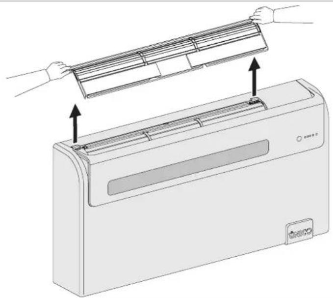
- unhook and manually remove the air intake filter acting as indicated in fig.22
- remove the two supplementary filters from the filter unit
- wash and dry all the filters
- refit the filter unit
To deactivate LED A (if on), after having powered and started the appliance, press the micro key positioned on the signal console (fig. 19 ref. H) with a pointy object for a brief instant. By doing so, the signal related to the filter cleaning requirement is reset.
3 USE AND MAINTENANCE (user part)
3.1 WARNINGS

The installation and electrical connection of the air conditioner should be carried out by specialized personnel who possess the requisites set forth by law. The installation instructions are contained in the appropriate paragraph of this manual.

No structural object (furniture, curtains, plants, leaves, blinds, etc.) should ever obstruct the normal flow of air from either the internal or external gratings.

Never lean or, worse yet, sit on the casing of the air conditioner as this could cause serious damage to the external parts.

Do not move the horizontal air outlet fin manually. Always use the remote control to adjust baffle position.

If the unit leaks water, switch it off immediately and disconnect it from the power mains. Call the nearest service centre.

When the air conditioner is heating, it has to periodically eliminate any ice that could form on the external battery. While it is doing this, the machine keeps running but does not heat the room. This lasts for a brief period of time, from 3 to a maximum of 10 minutes.

The air conditioner must not be installed in rooms where explosive gasses develop or where there are conditions of heat and humidity beyond the maximum limits indicated in the installation manual.

Clean the air filter periodically, as described in the specific paragraph.
3.1.1 Description of the warning panel (fig. 19)
G) Transparent area in which the signal is received from the remote control.
LED D) Green LED that indicates the machine is running (when the machine is in standby this light is off).
LED C) Yellow LED signals activation of the programming switch on and/or switch off.
LED B) Green LED that indicates the switching on of the cooling compressor.
LED A) Red LED that indicates the air filter may need cleaning.
H) Service micro-button (RESET)
3.2 MANAGING THE UNIT WITH THE REMOTE CONTROL
3.2.1 Remote control

The remote control supplied with the air conditioner is designed to be extremely sturdy and to ensure excellent performance in use, but it should nevertheless be handled with some care.
For example, do not:
- leave it out in the rain, spill water on its keyboard or drop it into water
- subject it to impacts or drop it onto hard surfaces
- leave it exposed to direct sunlight
- place obstacles between the remote control and the air conditioner while using it.
Furthermore:
if other devices operated by remote control (TV, radio, stereo systems, etc.) are located in the same room as the air conditioner, there may be interference,
electronic and fluorescent lighting may interfere with communications between the remote control and the air conditioner,
- remove the batteries in case of prolonged disuse of the remote control.
3.2.2 Fitting the batteries

The remote control exclusively requires 2 dry LR03 1.5 V batteries (not included with the supply).
Used batteries should be disposed of solely by depositing them into the appropriate collection points arranged by the Local Authorities specifically for this type of waste.
Replace both batteries at the same time.
To insert the batteries remove the spring-latch cover on the back of the remote control.
The batteries have to be inserted according to the positive and negative pole markings in the bottom of the battery compartment.
Close the spring-latch cover after inserting the batteries.
3.3 REMOTE CONTROL

The remote control is the interface between the user and the air conditioner. It is therefore particularly important to familiarize yourself with the parts of the remote control that relate to this interface.
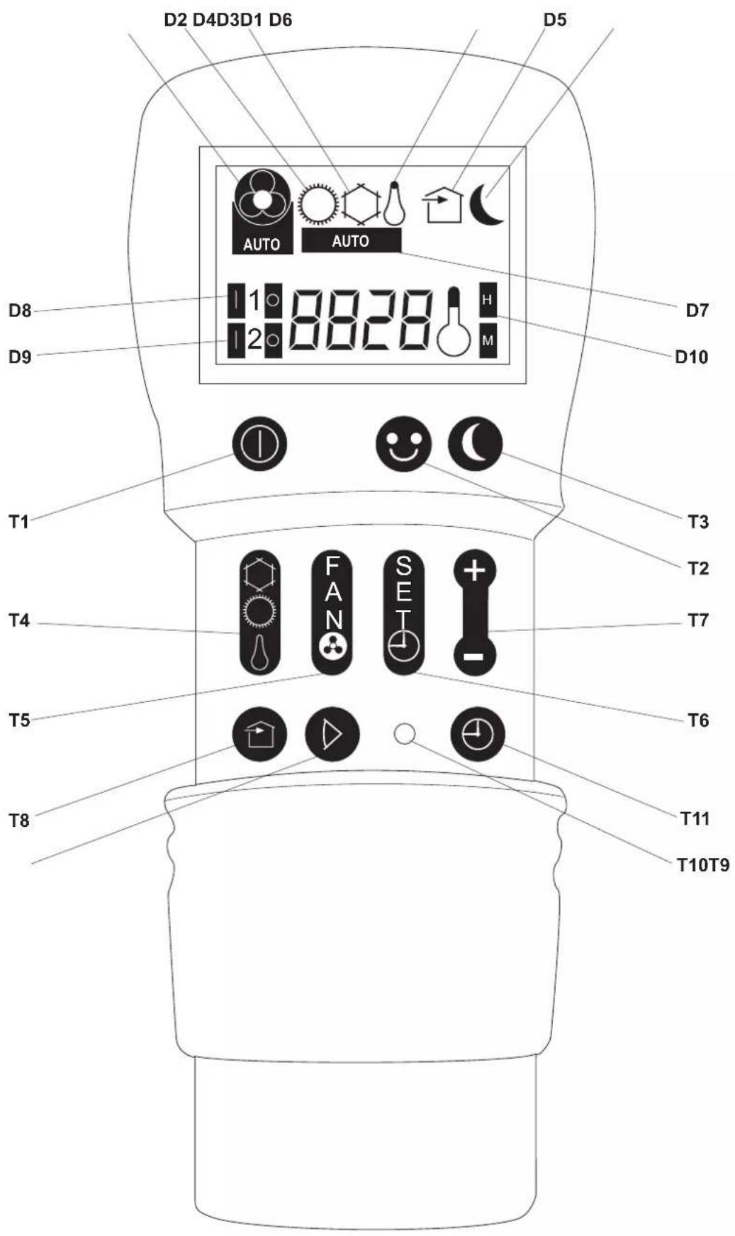
All the references indicated in the following paragraphs refer to figure 24 on page 8 (unless otherwise specified).
3.3.1 Description of the remote control
Buttons (fig. 24): used to set or bring up machine functions.
T1 ON/OFF (standby).
T2 Well-being key (automatic)
T3 Night well-being mode.
T4 Operating mode selector.
T5 Fan speed selector.
T6 Button for setting timer and programs.
T7 Button for increasing (+) or decreasing (-) the temperature/time settings.
T8 Button for activating the FREE COOLING air change system (not available in this model).
T9 Movable baffle adjustment On/Off button.
T10 Reset button.
T11 Program start button.
Display (fig. 24): shows the operating state and the values of the settings being carried out.
D1 Fan speed or automatic operating mode indicator (AUTO).
D2 Heating.
D3 Cooling.
D4 Dehumidifier only.
D5 Air change activation (not available in this model).
D6 Night operation switch.
D7 Automatic operation switch.
D8 First operating program switch.
D9 Second operating program switch.
D10 Temperature indicator (thermometer) or time indicator (H / M)
The remote control is also equipped with a sliding cover that can be positioned so as to permit access only to the ON/OFF, Automatic operating and NIGHT MODE buttons.
3.3.2 Main switch-on and running management
To manage the appliance with the remote control, it will be necessary to have activated the main switch which is included on the electrical power supply line (the technician that installed the appliance could offer more details regarding the position), or insert the power plug of the appliance into the socket of the system.
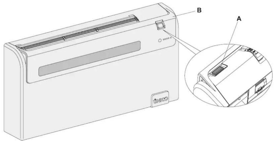
The machine is fitted with a power switch (fig. 23 ref. A) located below the lower safety guard (fig. 23 ref. B); to run it must be in "I" position.
Once these operations have been carried out, the machine may be regulated using the remote control.
In order to transmit commands to the indoor unit, point the front of the remote control toward the unit's control panel.
The device emits a beep when it receives a command.
The maximum distance for transmission of commands is about 8 meters.
3.3.3 Turning the unit ON/OFF
Using button T1 it is possible to switch off (stand-by) or switch on the system.
Since the machine's control system has a memory, no setting will not be lost when it is turned off.
This button serves to switch the air conditioner on or off for brief periods of time.

In case of prolonged stop of the machine, it must be deactivated turning the main switch off or unplugging the machine from the mains.
3.3.4 Well-being key (automatic operating)
By pressing button T2 the appliance will automatically arrange to obtain optimal comfort in the room that is conditioned. In relation to the internal temperature of the room, the conditioner will automatically set the operating mode (cooling, ventilation or, if available, heating), the temperature of the appliance and the fan speed.
3.3.5 Cooling
When used in this mode, the air conditioner dehumidifies and cools the room.
Activate this mode by pressing button T4 (Run mode selector) until the snowflake symbol D3 is displayed.
In this run mode, the required temperature and fan speed can be set. After three minutes (as a maximum) from activation in this operating mode the compressor will start and the appliance starts emitting cold air.
Start up of the compressor is indicated by the lighting up of the green LED B (fig. 19) positioned on the console.
3.3.6 Dehumidification only
When used in this mode, the air conditioner eliminates the humidity in the room. This function can be extremely useful between seasons, particularly on rainy days when the temperature is not uncomfortable but the excess humidity feels unpleasant.
In this mode, both room temperature and fan speed settings are ignored, which correspond to minimum.
As such, no temperature and fan speed indications are displayed.
Activate this mode by pressing button T4 (Run mode selector) until the droplet symbol D4 and automatic ventilation symbol D1 are displayed.
In this operating mode it is normal for the air conditioner to function intermittently.
3.3.7 Ventilation only
When used in this mode the air conditioner does not perform any action with regard to temperature and air humidity in the room. Activate this mode by pressing button T4 (Run mode selector) until the fan symbol D1 is displayed.
At this stage you can select the fan speed (see paragraph 3.3.10).
3.3.8 Heating (only models fitted with heating pump)
When used in this mode the air conditioner heats the room. This function is only available on models with a heating pump (HP). Activate this mode by pressing button T4 (Run mode selector) until the sun symbol D2 is displayed.
In this run mode, the required temperature and fan speed can be set. After three minutes (maximum time) the compressor should start and the air conditioner starts heating the room. The start of the compressor can be checked through the lighting of the relevant green LED located on the console.

NOTE: the air conditioner has to defrost its battery periodically. during this operation the air conditioner does not heat the room, though its internal parts remain on except for the room air fan. when the outdoor temperature is very low, there may be a slight delay for passage from the minimum to the medium or maximum speed from when the command is sent to the machine with the remote control.
Like delays might occur on activating the swinging function of the mobile baffle.
After having turned off the unit, the internal fan runs 60 seconds more. Then it stops and both air flaps close.
3.3.9 Air flow direction control
By pressing button T9 it is possible to activate/deactivate the continuous swing of the mobile air outlet baffle. When the continual swing is activated, one further press of button T9 will block the baffle so that the desired vertical direction of the air flow is obtained.

IMPORTANT: Movement of the mobile baffle must never be forced manually.
3.3.10 Checking fan speed
Fan speed is checked by button T5. Pressing this button several times will change the speed in this order: Low, Medium, High and Automatic.
The higher the speed setting, the greater the output of the air conditioner but also the louder its operation. By setting the Automatic mode, the onboard microprocessor adjusts the automatic speed. The higher the difference between the room temperature detected and the temperature set, the higher the speed.
As the room temperature nears the setting, fan speed is reduced automatically.
In dehumidification mode, it is not possible to control the speed as the appliance can only operate exclusively at low speed.
3.3.11 Night well-being key
Press the T3 button (night well-being) to obtain several results, specifically:
- Gradual increase of the set cooling temperature.
- Gradual decrease of the temperature set for heating (only HP models).
- Decrease of the unit's noise level.
- Savings on night-time consumption of electricity.
In order to activate the Night well-being key press button T3 press after having selected the required operating mode through button T4 and having set the required temperature through button T7.
Ideally, you should start night well-being mode operation just before you fall asleep.
In cooling, the set temperature is maintained for one hour after activating the night-time comfort button. During the next two hours the setting increases gradually, whilst the running of the fan is set to low speed. After the second hour, the temperature and fan speed settings do not change any longer.
In heating mode, the set temperature is held for one hour after starting Night well-being mode operation.
During the next two hours the setting decreases gradually, whilst the running of the fan is set to low speed.
After the second hour, the temperature and fan speed settings do not change any longer.
The 'night well-being' key is not available when the unit operates in dehumidification and ventilation mode.
The night well-being mode button may be disabled at any time (ideally when you wake up in the morning) by pressing button T3 again.
At this stage the temperature and fan speed settings made prior to starting Night well-being mode operation go back into effect.
3.3.12 Setting the operating programs
The air conditioner logic provides the user with a choice of two operating programs that can be set to start and stop at programmed times, for example you might want the air conditioner to start shortly before you return home so that it is cool when you get there. To use these functions it is first necessary to set the exact time on the remote control and then set the time for the programs to start.
3.3.13 Setting the exact time
Proceed as follows to set the exact time:
a) Press button T6 (Time and Program Setting), as many times as necessary to display the hour indication H D10.
b) Press the toggle button T7 to increase or decrease the displayed hour until it matches the exact time.
c) Press button T6 again to display the minutes indication M D10.
d) Press the toggle button T7 to increase or decrease the displayed minutes until it shows the exact time in minutes.
3.3.14 Setting the times of the 1st and 2nd the operating programs (PROGR. 1 and PROGR. 2)
To set the times for starting and stopping the two air conditioner programs, proceed as follows:
a) Press button T6 (Time and Program Setting), as many times as necessary to display the indication 1 (Time to start the 1st program).
b) Press the toggle button T7 to increase or decrease the display of the time when you want program 1 to start. Every time you press one end of the toggle button the time increases or decreases by 30 minutes.
c) Press button T6 (Time and Program Setting) once again to display the indication 1 (Time to stop the 1st program).
d) Press the toggle button T7 to increase or decrease the indication of the time when you want program 1 to stop. Every time you press one end of the toggle button the time increases or decreases by 30 minutes.
e) Press button T6 (Time and Program Setting) once again to display the indication 12 (Time to start the 2nd program).
f) Press the toggle button T7 to increase or decrease the display of the time when you want program 2 to start. Every time you press one end of the toggle button the time setting increases or decreases by 30 minutes.
g) Press button T6 (Time and Program Setting) once again to display the indication 2 (Time to stop the 2nd program).
h) Press the toggle button T7 to increase or decrease the indication of the time when you want program 2 to stop. Every time you press one end of the toggle button the time increases or decreases by 30 minutes.
i) To return to the routine operating mode just press the button T6 as many times as necessary to clear the relevant indications from the display.
3.3.15 Starting and stopping the operating programs
After having made the settings for the operating programs, they can be used or not, as needed.
Either or both of the programs can be used.
In particular, each time you press the button T11 (Program activation), the situation changes as follows:
Use of Program no. 1 only.
Use of Program no. 2 only.
Use of Programs 1 and 2.
Disuse of both programs..
3.3.16 Resetting all remote control functions
Press the button T10 to reset all the remote control settings.
By doing so all of the settings of the timer are cancelled and the remote control restores all of the default settings.
Furthermore, by pressing button T10, all of the symbols indicated in fig. 24 will appear on the display, thus making it possible to check the integrity of the display itself.
3.3.17 Managing the unit if the remote control is not available
Should the remote control be lost, the batteries flat or if it is faulty, the appliance may be operated only in automatic mode by pressing the micro switch positioned underneath the hole located on the console by means of a pointy object.
To switch the air-conditioner off, press the microswitch again.
To restore routing operations in the remote control, you need only issue any command once the remote control is available again.
3.4 ENERGY SAVING ADVICE
- Always keep the filters clean (see chapter on maintenance and cleaning).
- Keep the doors and windows closed in the air-conditioned rooms.
- Keep sunlight out of the room by using curtains, lowering the shades or closing the shutters.
Do not obstruct the air flow channels (both inlet and outlet) of the unit; apart from preventing the optimal performance of the system, this would also jeopardise correct operating and could cause irreparable damage to the unit.
3.5 DIAGNOSIS OF THE PROBLEMS
It is important for the User to distinguish between functional problems and anomalies in relation to the behaviour of the appliance as foreseen for its normal operation. Furthermore, the most common problems may easily be solved through simple operations on behalf of the User (See paragraph: Anomalies and solutions), while for all of the other anomalies it is necessary to contact the Olimpia Splendid Service Centre.

WARNING: Please remember that any attempt to repair the appliance by unauthorised personnel will immediately invalidate any form of guarantee.
3.5.1 Functional aspects not to be interpreted as problems
- The compressor does not start up again immediately after a stop (it takes about three minutes to start again).
In the operating logic of the appliance a delay between a compressor stop and its successive restart has been included, so that the compressor itself is protected against activations that are too frequent.
During the heating operation of the heat pump appliances, the flow of hot air may occur some minutes after activation of the compressor.
Should the fan start at the same time as the compressor, for the first few minutes it would emit cold air into the room (and this could bother the occupants) since the unit has not yet reached steady running conditions.
3.5.2 Troubleshooting

In case of malfunctions, check the following table.
If the problem persists after the suggested checks and controls, contact the authorised technical service.
| FAULTS POSSIBLE CAUSES SOLUTIONS | ||
| The unit does not turn on | • No power supply | |
| • The power switch is in "0" position | ||
| • Remote control batteries are flat | ||
| The unit does not cool or heat adequately | • The temperature set on the remote control is either too high or too low (when using the heating pump unit). • The air filter has been blocked before the respective cleaning LED was switched on. • Indoor or outdoor air flow obstacles are present. • The heating/cooling load has increased (for example a door or a window was left open or equipment that dissipates a large amount of heat was installed in the same room); | • Check that mains power is present (by turning on a light for instance). • Check if the master switch is closed or if a fuse is burnt (in this case replace the fuse). If there is a magnetothermal circuit breaker instead of the master switch, check if it tripped (if it did, rearm it). Should the problem occur again, contact the Service Center at once and do not attempt to run the unit. • Move the power switch to "1" position (fig. 23 ref.A). • If the batteries are flat, you will notice that no messages are displayed and that the unit's reception confirmation sound is missing when you try to issue any command to it. In this case replace the batteries. • Check the temperature setting on the remote control and correct it if need be. • Check the air filter and clean it if necessary. • Remove anything that might clog the air flows. |
3.5.3 Specifications
For the technical data listed below, consult the characteristic data plate applied to the product
- Power supply voltage
Maximum power absorbed
Maximum current absorbed - Coolant power
Coolant gas
Protection rating of the containers - Max working pressure
hermetically sealed equipment
Contains fluorinated greenhouse gas R-410A
| Model | UNICO AIR 8 SF | UNICO AIR 8 HP |
| Refrigerant charge kg | 0,48 | 0,48 |
Since the charge may be subject to change, refer to the machine's specifications plate.
Dimensions (W× H× D) mm 980 x 490 x 160
Weight (without packing) kg 37
OPERATIONAL LIMITS Internal ambient temp. Outside ambient temp.
Maximum operating temperature DB 35^ - WB 24^ DB 43^ WB 32^ in cooling mode
Minimum operating temperature DB 18^ DB -10^ in cooling mode
Maximum operating temperatures DB 27^ DB 24^ WB 18^ in heating
Minimum operating temperatures - DB -15°C in heating

AVERTISSEMENTS
ANOMALIES CAUSES POSSIBLE REMEDES
DESCRIPCION LEDDLED CLEDB LEDA