
imageRUNNER ADVANCE 400i - Printer CANON - Free user manual and instructions
Find the device manual for free imageRUNNER ADVANCE 400i CANON in PDF.

User questions about imageRUNNER ADVANCE 400i CANON
0 question about this device. Answer the ones you know or ask your own.
Ask a new question about this device
Download the instructions for your Printer in PDF format for free! Find your manual imageRUNNER ADVANCE 400i - CANON and take your electronic device back in hand. On this page are published all the documents necessary for the use of your device. imageRUNNER ADVANCE 400i by CANON.
USER MANUAL imageRUNNER ADVANCE 400i CANON
Before using this manual, see "READ THIS SHEET FIRST!" and unpack the machine.
Please read this guide before operating this product.
After you finish reading the guide, store it in a safe place for future reference.
Guide de démarrage
The manuals for this machine are divided as follows. Please refer to them for detailed information.

Guides with this symbol are printed manuals.

Guides with this symbol are included on the accompanying CD-ROM.

Starter Guide (This Manual)
Describes how to install the machine.
Describes the initial settings configured by the Setup Guide.
Describes the maintenance and troubleshooting procedures for the machine.

Quick Operation Guide
Describes useful functions and the basic operations of each function.

e-Manual (HTML manual)
Describes all the functions of the machine. Also provided with a search function that is useful for finding and checking information.
Includes "Practical Workflows," which introduces flows of practical operations using functions of the machine.

Driver Installation Guide
Provides instructions on installing the printer, fax, and other drivers.
Printer Driver Installation Guide -
Mac Printer Driver Installation Guide -
Fax Driver Installation Guide -
Network ScanGear Installation Guide
- Included on the same CD-ROM as each driver.
To view the manual in PDF format, Adobe Reader/Acrobat Reader/Acrobat is required. If Adobe Reader/Acrobat Reader/Acrobat is not installed on your system, please download it from the Adobe Systems Incorporated website (http://www.adobe.com).
How to Use the e-Manual
How to Install the e-Manual
This section describes how to install the e-Manual.
Windows ●
-
Insert the e-Manual CD-ROM in your computer.
-
Select the language for the e-Manual.
-
Select [Install].
If you select [Display Manuals], the e-Manual is displayed without installation.
- Read the License Agreement, and then click [Yes]. The e-Manual is saved in the [Documents]* folder on your computer. If the shortcut icon created on the Desktop or if the [index.html] file is double-clicked, the e-Manual is displayed.
* The folder name differs depending on the OS you are using. For Windows Vista/7/8, the folder name is [Documents]. For Windows XP, the folder name is [My Documents].
Macintosh ●
- Insert the e-Manual CD-ROM into your computer.
- Drag-and-drop the [uk_iRADV_500i_Manual] folder to the location you want to save the e-Manual.
- Double-click the [index.html] file inside the [uk_iRADV_500i_Manual] folder to display the e-Manual.
Depending on the operating system you are using, a security protection message may appear. In this case, allow the content to be displayed.
If the e-Manual (CD-ROM) Does Not Start
The CD-ROM auto run function may be disabled. In this case, you must perform the following procedure.
Windows 7 ●
- Click [Start] on the task bar → click [Computer].
- Double-click the e-Manual icon.
- Double-click [Maninst.exe].
Windows XP/Vista ●
- Click [Start] on the taskbar → click [My Computer].
- Double-click the e-Manual icon.
- Double-click [Maninst.exe].
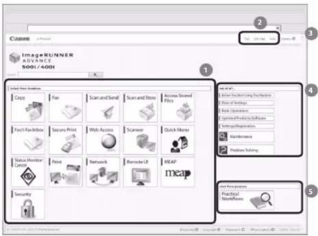
Top Page of the e-Manual
text_image
Canon ImageRUNNER ADVANCE 5001/4001 Select Files Options Copy Fax Scan and Send Scan and Store Access Stored Files Fool/Fool Inbox Secure Print Web Access Scanner Quick Mouse Status Monitor Control Print Network Remote LR MEAP meap Set to All... Select File From Using Tools File of Settings Save Settings Options Products/Systems Software Registration Maintenance Position Solving Start From Process Practical Workflows1 Select from functions
The instructions for each function and operation method are described.
2 [Top], [Site map], [Help]
Links to the e-Manual's top page, site map, and help are displayed.
3 [Glossary]
A link to the glossary is displayed.
4 First of all...
This section contains required information needed to use the machine, and information on optional products and software.
5 Select from purpose
This section includes an introduction for each function of the machine and their purpose.
Contents
Preface 01
How To Use This Manual 01
Symbols Used in This Manual 01
Keys and Buttons Used in This Manual 01
Displays Used in This Manual....01
Illustrations Used in This Manual 02
Abbreviations Used in This Manual....02
Trademarks....02
Installation of the MachinChapter 1 e
Installation Location and Handling 06
Installation Precautions....06
Avoid Installing the Machine in the Following Locations 06
Select a Safe Power Supply....07
Moving the Machine 08
Provide Adequate Installation Space 08
Handling Precautions 08
Items Included with the Machine 10
Carrying the Machine to the Installation Site and Removing the Packing Materials 11
Installing the Filters.... 12
Attaching the Duplex Tray and the Tray Rib 13
Installing the Drum Unit 14
Installing the Toner Cartridge.... 17
Loading Paper into the Paper Drawer 19
Attaching the Precaution Label 21
Connecting the Power Cord.... 22
Chapter 2 Setting and Registering the Machine
Main Power and Energy Saver Key 24
How to Turn ON the Main Power 24
Energy Saver Key 25
Shutting Down the Machine 25
Using the Setup Guide to Configure the Machine 26
Changing Specified Settings.... 33
Before Using This MachinChapter 3 e
Parts and Their Functions.... 36
External View 36
Internal View....37
Feeder 37
Control Panel Parts and Functions 38
Adjusting the Angle of the Control Panel....39
Backing Up/Exporting Data.... 40
Data You Can Import/Export All....40
Data You Can Import/Export Individually....40
Other Data You Can Import/Export 40
Routine MaintenancChapter 4 e
Loading Paper 42
Loading Paper into a Paper Drawer 42
Adjusting a Paper Drawer to Hold a Different Paper Size 43
Replacing the Toner Cartridge/Waste Toner Container 45
Replacing the Toner Cartridge....45
Replacing the Waste Toner Container 47
Replacing the Drum Unit.... 50
Routine Cleaning 54
Cleaning the Platen Glass and Underside of the Feeder 54
Manual Feeder Cleaning 54
Consumables 57
When an Error Message/Error Code Is Displayed 59
When an Error Message Is Displayed....59
When an Error Code Is Displayed....59
Service Call Message.... 60
Contacting Your Local Authorized Canon Dealer 60
Setting the Limited Functions Mode from the Service Call Message Screen 61
Functions Available When the Printer/Scanner Cannot Be Used Due to an Error....61
Locations of Staple/Paper Jams 63
Chapter 5 Specifications
Specifications....66
Main Unit 66
Feeder 68
Cassette Module-AA1 68
EMC requirements of EC Directive 75
Laser Safety....75
Additional Information....75
International ENERGY STAR Program 75
IPv6 Ready Logo....76
WEEE Directive 76
R & TTE Directive....76
Information Security Standard (IEEE 2600)....76
Copyright....76
Third Party Software 77
The Software Subjected to the Other Conditions....77
Disclaimers 77
Legal Limitations on the Usage of Your Product and the Use of Images ....77
Super G3....78
Important Safety Instructions 79
Installation....79
Power Supply....79
Handling....80
Maintenance and Inspections....81
Consumables....82
Other Warnings....83
Preface
Thank you for purchasing the Canon imageRUNNER ADVANCE 500i/400i. Please read this manual thoroughly before operating the machine to familiarize yourself with its capabilities, and to make the most of its many functions. For information on the detailed settings for the functions described in this manual, see the e-Manual. After reading this manual, store it in a safe place for future reference.
How To Use This Manual
Symbols Used in This Manual
The following symbols are used in this manual to explain procedures, restrictions, handling precautions, and instructions that should be observed for safety.

WARNING
Indicates a warning concerning operations that may lead to death or injury to persons if not performed correctly. To use the machine safely, always pay attention to these warnings.

CAUTION
Indicates a caution concerning operations that may lead to injury to persons if not performed correctly. To use the machine safely, always pay attention to these cautions.

IMPORTANT
Indicates operational requirements and restrictions. Be sure to read these items carefully to operate the machine correctly, and avoid damage to the machine or property.

NOTE
Indicates a clarification of an operation, or contains additional explanations for a procedure. Reading these notes is highly recommended.

Indicates an operation that must not be performed. Read these items carefully, and make sure not to perform the described operations.
Keys and Buttons Used in This Manual
The following symbols and key/button names are a few examples of how keys and buttons to be clicked or pressed are expressed in this manual:
Touch Panel Display Keys: [Key Name] •
Example: [Cancel]
[Close]
Control Panel Keys: Key Icon (Key Name) •
Example:
(Start)
(Stop)
Buttons on Computer Operation Screens: [Button • Name]
Example: [OK]
[Add]
Displays Used in This Manual
Screen shots of the touch panel display used in this manual are those taken when the imageRUNNER ADVANCE 500i has the following optional equipment attached to it:
Staple Finisher-R1·
Cassette Module-AA1•
Super G3 FAX Board•
Web Access Software•
Note that functions that cannot be used depending on the model or options do not appear on the touch panel display.
The keys which you should press are marked with a ☐, as shown below. When multiple keys can be pressed on the touch panel display, all keys are marked. Select the keys, which suit your needs.
Screen shots used in this manual may differ from the ones you actually see.
01 Press [Copy].
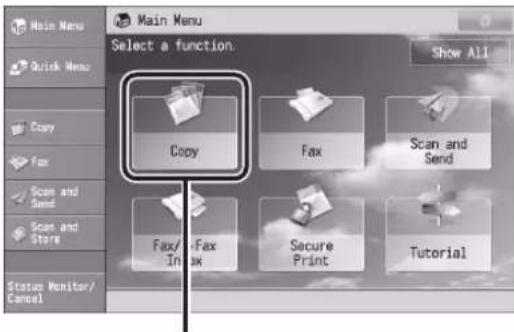
text_image
Main Menu Select a function. Show All Copy Fax Scan and Send Fax/ -Fax In fax Secure Print Tutorial Status Monitor/ CancelPress this key for operation.
Illustrations Used in This Manual
Illustrations used in this manual are those displayed when the imageRUNNER ADVANCE 500i has the following optional equipment attached to it:
Staple Finisher-R1·
Cassette Module-AA1·
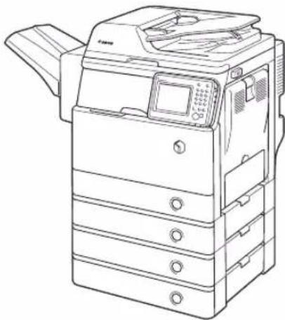
natural_image
Line drawing of a desktop computer with multiple rack units and a front panel (no text or symbols)Abbreviations Used in This Manual
In this manual, product names and model names are abbreviated as follows:
Microsoft Windows Server 2003 operating system: Windows Server 2003
Microsoft Windows Server 2003 R2 operating system: Windows Server 2003 R2
Microsoft Windows XP operating system: Windows XP Microsoft Windows Vista operating system: Windows Vista
Microsoft Windows Server 2008 operating system: Windows Server 2008
Microsoft Windows Server 2008 R2 operating system:
Windows Server 2008 R2
Microsoft Windows Server 2012 operating system: Windows Server 2012
Microsoft Windows 7 operating system: Windows 7 Microsoft Windows 8 operating system: Windows 8 Microsoft Windows operating system: Windows
Microsoft Internet Explorer: Internet Explorer
Microsoft Windows Internet Explorer: Internet Explorer Novell NetWare: NetWare
Apple Macintosh: Macintosh•
Apple Mac: Mac•
Trademarks
MEAP and the MEAP logo are trademarks of Canon Inc.
This product contains the Universal Font Scaling Technology or UFST ^® under license from Monotype Imaging, Inc. UFST ^® is a trademark of Monotype Imaging, Inc. registered in the United States Patent and Trademark Office and may be registered in certain jurisdictions.
Apple, EtherTalk, LocalTalk, Mac, Macintosh, Mac OS, and Safari are trademarks of Apple Inc., registered in the U.S. and other countries.
Microsoft, Windows, Windows Vista, Windows Server, Internet Explorer, Excel and PowerPoint are either registered trademarks or trademarks of Microsoft Corporation in the United States and/or other countries.

Adobe® PostScript® 3™
Adobe, PostScript, and the PostScript logo are either registered trademarks or trademarks of Adobe Systems Incorporated in the United States and/or other countries.
Copyright © 2007 -08 Adobe Systems Incorporated. All rights reserved.
Protected by U.S. Patents 5,737,599; 5,781,785; 5,819,301; 5,929,866; 5,943,063; 6,073,148; 6,515,763; 6,639,593; 6,754,382; 7,046,403; 7,213,269; 7,242,415; Patents pending in the U.S. and other countries.
All instances of the name PostScript in the text are references to the PostScript language as defined by Adobe Systems Incorporated unless otherwise stated.
The name PostScript also is used as a product trademark for Adobe Systems' implementation of the PostScript language interpreter.
Except as otherwise stated, any reference to a "PostScript printing device," "PostScript display device," or similar item refers to a printing device, display device or item (respectively) that contains PostScript technology created or licensed by Adobe Systems Incorporated and not to devices or items that purport to be merely compatible with the PostScript language.
Adobe, the Adobe logo, PostScript, the PostScript logo, and PostScript 3 are either registered trademarks or trademarks of Adobe Systems Incorporated in the United States and/or other countries.
Linux is a registered trademark of Linus Torvalds. Microsoft and Windows are either registered trademarks or trademarks of Microsoft Corporation in the United States and/or other countries.
All other trademarks are the property of their respective owners.

text_image
Adobe® PDFThe PDF logo is a trademark or registered trademark of Adobe Systems Incorporated in the United States and other countries.
Copyright © 2008 Adobe Systems Incorporated. All rights reserved.
Protected by U.S. Patents 6,185,684; 6,205,549; 7,213,269; 7,272,628; 7,278,168; Patents pending in the U.S. and other countries.
All instances of the name PostScript in the text are references to the PostScript language as defined by Adobe Systems Incorporated unless otherwise stated. The name PostScript also is used as a product trademark for Adobe Systems' implementation of the PostScript language interpreter.
Except as otherwise stated, any reference to a "PostScript printing device," "PostScript display device," or similar item refers to a printing device, display device or item (respectively) that contains PostScript technology created or licensed by Adobe Systems Incorporated and not to devices or items that purport to be merely compatible with the PostScript language.
Adobe, the Adobe logo, PostScript, the PostScript Logo, and PostScript 3 are either registered trademarks or trademarks of Adobe Systems Incorporated in the United States and/or other countries.
All other trademarks are the property of their respective owners.
Other product and company names herein may be the trademarks of their respective owners.
Installation of the Machine
1
Installation Location and Handling....06
Installation Precautions....06
Handling Precautions....08
Items Included with the Machine 10
Carrying the Machine to the Installation Site and Removing the Packing Materials ... 11
Installing the Filters 12
Attaching the Duplex Tray and the Tray Rib 13
Installing the Drum Unit....14
Installing the Toner Cartridge 17
Loading Paper into the Paper Drawer.... 19
Attaching the Precaution Label.... 21
Connecting the Power Cord 22
Installation Location and Handling
This section describes precautions for installation location and handling. We recommend that you read this section prior to using this machine.
Installation Precautions
Avoid Installing the Machine in the Following Locations
Avoid locations subject to temperature and humidity extremes, whether low or high.
For example, avoid installing the machine near water faucets, hot water heaters, humidifiers, air conditioners, heaters, or stoves.
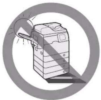
natural_image
Illustration of a printer with two circular insets showing mechanical components (no text or symbols)Avoid installing the machine in direct sunlight. ● If this is unavoidable, use curtains to shade the machine. Be sure that the curtains do not block the machine's ventilation slots or louvers, or interfere with the electrical cord or power supply.
natural_image
Illustration of a printer with a magnifying glass, enclosed in a circular frame (no text or symbols)Avoid poorly ventilated locations. ●
This machine generates a slight amount of ozone etc. during normal use. Although sensitivity to ozone etc. may vary, this amount is not harmful. Ozone etc. may be more noticeable during extended use or long production runs, especially in poorly ventilated rooms. It is recommended that the room be appropriately ventilated, sufficient to maintain a comfortable working environment, in areas of machine operation.
natural_image
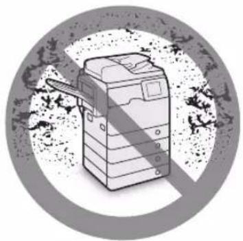
Illustration of a printer with a diagonal line, set against a circular background (no text or symbols)Avoid locations where a considerable amount of ● dust accumulates.
Avoid locations where ammonia gas is emitted. ●
natural_image
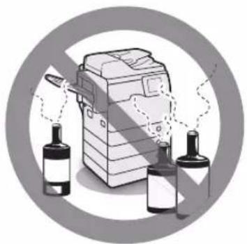
Illustration of a printer with three bottles and a paper airplane, enclosed in a circular frame (no text or symbols)Avoid locations near volatile or flammable materials, such as alcohol or paint thinner.
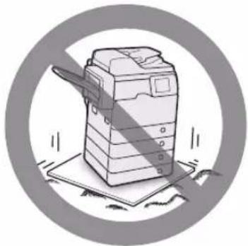
Avoid locations that are subject to vibration. ●
For example, avoid installing the machine on unstable floors or stands.
natural_image
Illustration of a printer with a spool and paper plane, enclosed in a circular frame (no text or symbols)Avoid exposing the machine to rapid changes in ● temperature.
If the room in which the machine is installed is cold but rapidly heated, water droplets (condensation) may form inside the machine. This may result in a noticeable degradation in the quality of the copied image, the inability to properly scan an original, or the copies having no printed image at all.
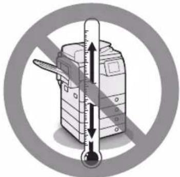
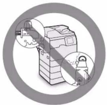
text_image
Diagram showing a thermometer measuring a printer, enclosed in a prohibition symbol with a magnified view of the device.Avoid installing the machine near computers or other precision electronic equipment.
Electrical interference and vibrations generated by the machine during printing can adversely affect the operation of such equipment.
Avoid installing the machine near televisions, ● radios, or similar electronic equipment.
The machine might interfere with sound and picture signal reception.
Insert the power plug into a dedicated power outlet, and maintain as much space as possible between the machine and other electronic equipment.
Contact an authorized Canon dealer if ● communication is unavailable.
Depending on your locale or your telephone connection, you may be unable to perform data communication. In this case, contact your local authorized Canon dealer.
Do not remove the machine's leveling feet. ●
Do not remove the machine's leveling feet after the machine has been installed.
If you put weight on the front of the machine while the drawers or units within the machine are pulled out, the machine may fall forward. To prevent this from happening, make sure that the machine's leveling feet are in place.
Select a Safe Power Supply
Plug the machine into a 220 - 240 V AC outlet. ●
Make sure that the power supply for the machine ● is safe, and has a steady voltage.
Do not connect other electrical equipment to the same power outlet to which the machine is connected.
Do not connect the power cord to a multiplug ● power strip, as this may cause a fire or electrical shock.
The power cord may become damaged if it is ● stepped on, affixed with staples, or if heavy objects are placed on it. Continued use of a damaged power cord can lead to an accident, such as a fire or electrical shock.
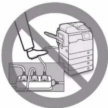
natural_image
Illustration of a hand using a device to switch a cable, with an inset showing the cable being inserted (no text or symbols present)The power cord should not be taut, as this may lead to a loose connection and cause overheating, which could result in a fire.
Excessive stress is applied to the connection part of the power cord, it may damage the power cord or the wires inside the machine may disconnect.
This could result in a fire. Avoid the following situations:
- Connecting and disconnecting the power cord frequently.
- Tripping over the power cord.
- The power cord is bent near the connection part, and continuous stress is being applied to the power outlet or the connection part.
- Applying excessive force on the power plug.
Moving the Machine
If you intend to move the machine, even to a ● location on the same floor of your building, contact your local authorized Canon dealer beforehand. Do not attempt to move the machine yourself.
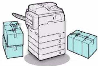
natural_image
Illustration of a printer with two teal box cases, no text or symbols presentProvide Adequate Installation Space
Provide enough space on each side of the machine for unrestricted operation.
When no optional products are attached: ●
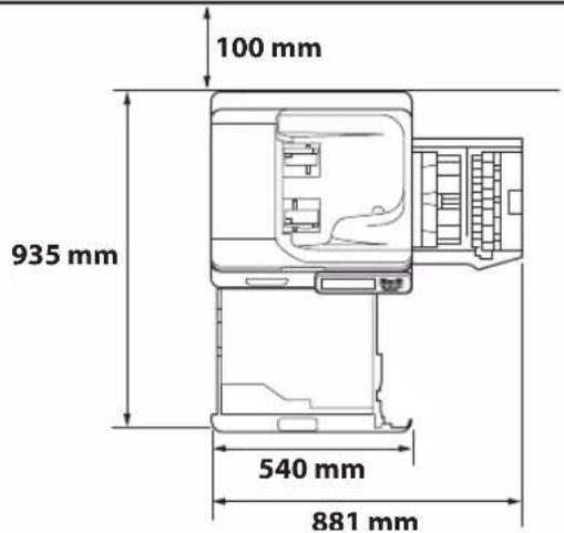
text_image
100 mm 935 mm 540 mm 881 mmWhen the Staple Finisher-R1 is attached: ●
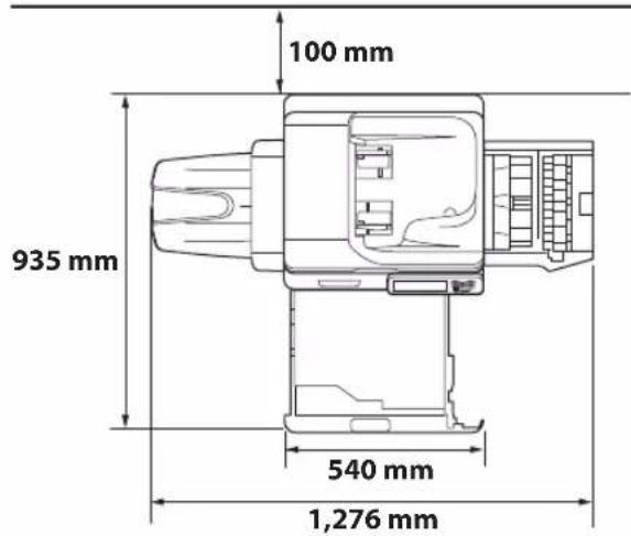
text_image
100 mm 935 mm 540 mm 1,276 mmHandling Precautions
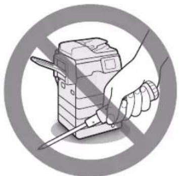
Do not attempt to disassemble or modify the machine.
natural_image
Illustration of a hand holding a pen inside a device, enclosed in a circular frame (no text or symbols)Some parts inside the machine are subject to high-voltages and temperatures. Take adequate precautions when inspecting the inside of the machine. Do not carry out any inspections that are not described in the manuals for this machine.
Be careful not to spill liquid or drop any foreign objects, such as paper clips or staples inside the machine. If a foreign object comes into contact with electrical parts inside the machine, it might cause a short circuit and result in a fire or electrical shock.

natural_image
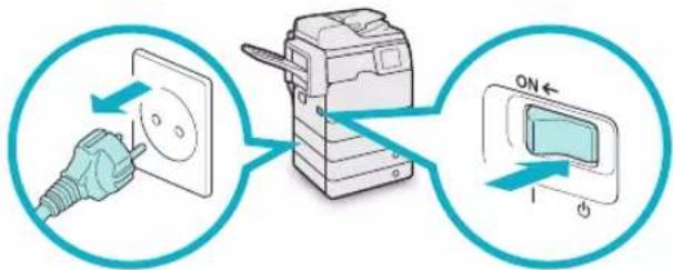
Symbolic illustration of a printer with a paperclip and tools, crossed out by a diagonal line (no text or symbols present)If there is smoke, or unusual noise, immediately turn the main power switch OFF, disconnect the power cord from the power outlet, and then call your local authorized Canon dealer. Using the machine in this state may cause a fire or electrical shock. Also, avoid placing objects around the power plug so that the machine can be disconnected whenever necessary.
text_image
Diagram showing electrical connection with a plug, switch, and screen, labeled with ON/OFF statesDo not turn the main power switch OFF or open ● the front covers while the machine is in operation. This may result in paper jams.
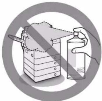
Do not use flammable sprays, such as spray glue, near the machine. There is a danger of ignition.
natural_image
Illustration of a hand pouring liquid from a container onto a box, enclosed in a circular frame (no text or symbols)This machine generates a slight amount of ozone etc. during normal use. Although sensitivity to ozone etc. may vary, this amount is not harmful. Ozone etc. may be more noticeable during extended use or long production runs, especially in poorly ventilated rooms. It is recommended that the room be appropriately ventilated, sufficient to maintain a comfortable working environment, in areas of machine operation.
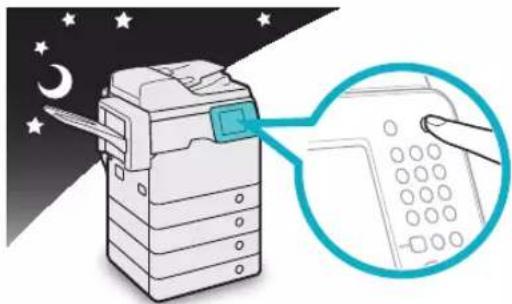
For safety reasons, press (Energy Saver) when it will not be used for a long period of time, such as overnight. As an added safety measure, turn OFF the main power switch, and disconnect the power cord when the machine will not be used for an extended period of time, such as during consecutive holidays.
natural_image
Illustration of a printer with a magnified view showing its screen and keypad (no text or symbols present)Use a modular cable that is shorter than 3 ● meters.
Use a USB cable that is shorter than 3 meteres. ●
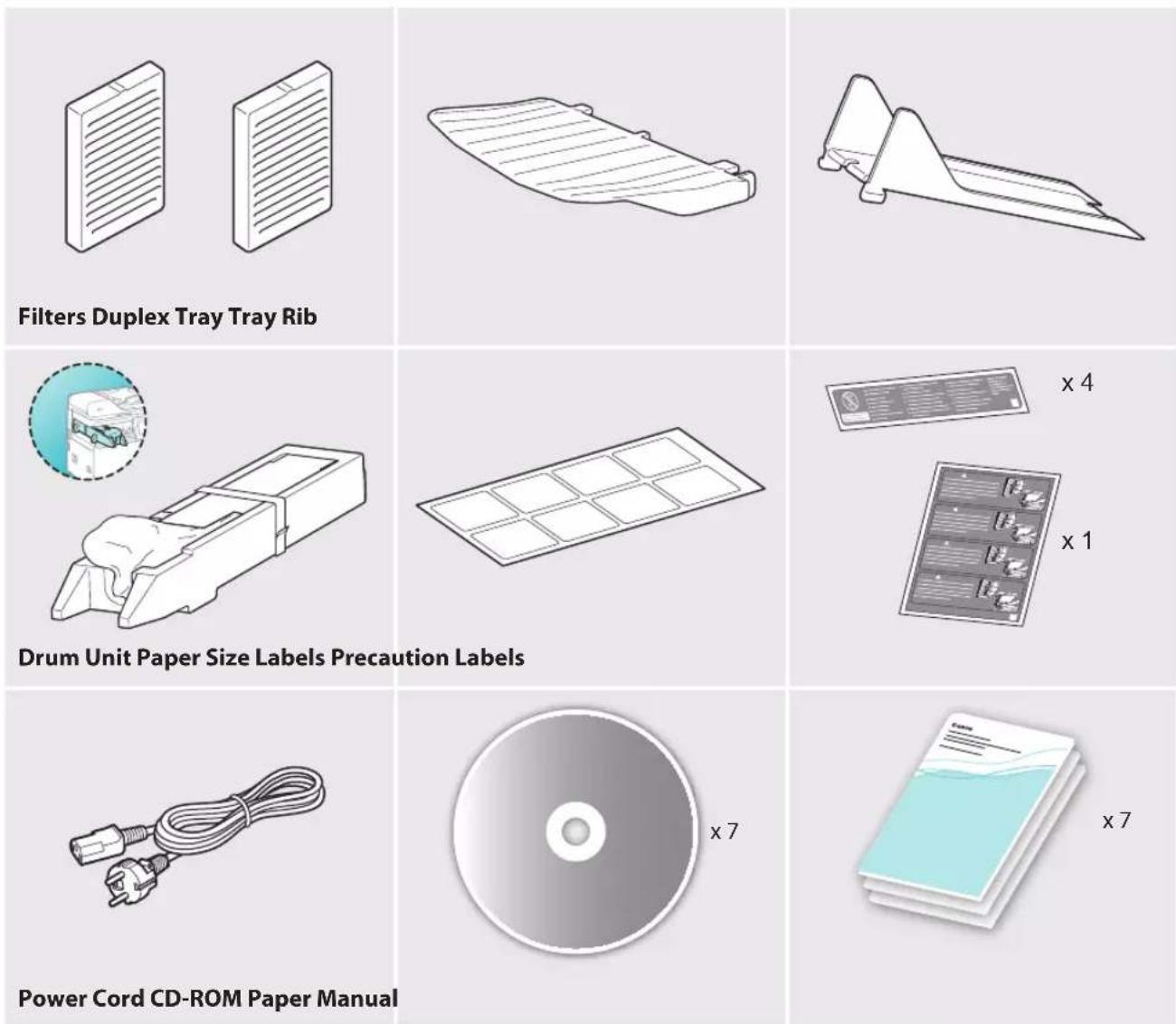
Items Included with the Machine
In the next section "Carrying the Machine to the Installation Site and Removing the Packing Materials," check each item against this list as you remove each item from the accessories box (except for the drum unit).
Carrying the Machine to the Installation Site and Removing the Packing Materials
01
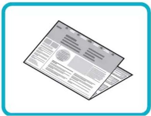
text_image
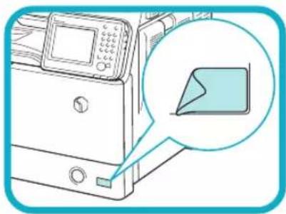
Illustration of a generic document layout with text blocks and a placeholder, enclosed in a blue rounded square frame.See the included "READ THIS SHEET FIRST!" before carrying the machine to the installation site.
02
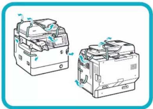
natural_image
Illustration of two electronic devices with heat exchangers and ventilation ducts (no text or symbols)Remove all shipping tape from the flap side edges.
03
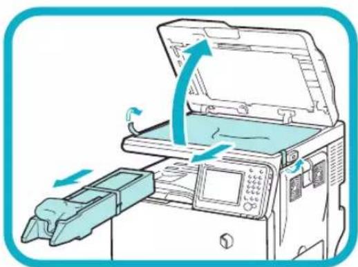
natural_image
Illustration of a printer with an open lid and directional arrows indicating motion (no text or symbols)Open the feeder, remove the protective sheet, and take out the drum unit.
Installing the Filters
01
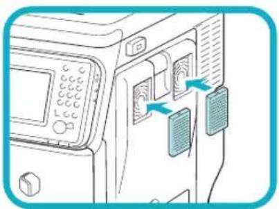
natural_image
Line drawing of a device's front panel with buttons and control buttons, showing no text or symbolsInstall the filters on the right side of the machine.
Attaching the Duplex Tray and the Tray Rib
If you are attaching the optional Staple Finisher-R1 to the machine, the following steps are not necessary. Go to the next section, "Installing the Drum Unit."
01
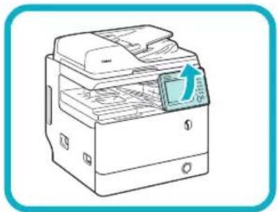
natural_image
Illustration of a printer with a paper feed and a blue arrow indicating the print direction (no text or symbols present)Lift the control panel.
02
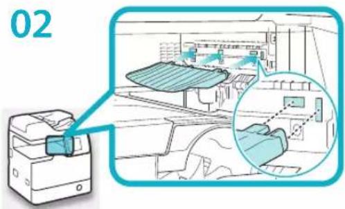
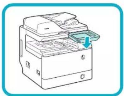
text_image
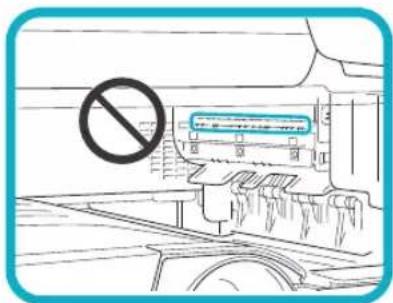
02Attach the duplex tray by inserting its tabs into the slots on the machine.
text_image
Safety warning sign with Chinese text indicating no hazard, featuring a blue box and a prohibition symbol.
IMPORTANT
Be careful not to accidentally insert the tabs into the slot circled in the illustration.
03
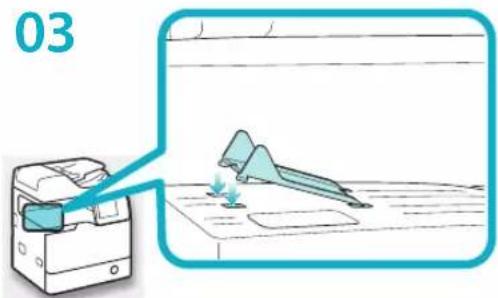
text_image
03Insert the front tabs of the tray rib into the slots first and then press down on its left end so that the rear tabs snap into the slots.
04
natural_image
Line drawing of a printer with a paper feed insert, showing internal structure without any text or symbolsLower the control panel back in place.
Installing the Drum Unit
01
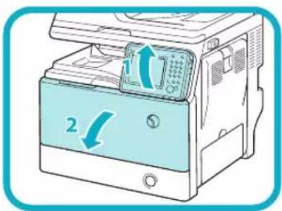
text_image
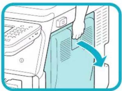
Diagram showing a printer with two labeled parts (1 and 2) indicating directional changes in the device's operation.Open the front cover.
- Lift the control panel.
- Open the front cover.
02
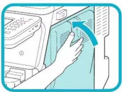
natural_image
Illustration of a hand pressing down on a printer's side panel with a blue arrow indicating the process (no text or symbols present)Open the right cover.

IMPORTANT
Always open the right cover during installation to prevent damage to the drum unit.
03
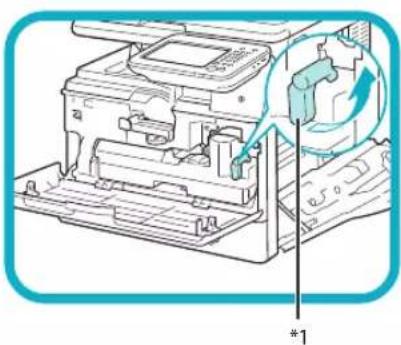
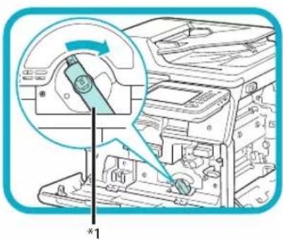
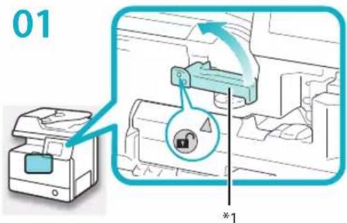
text_image
Technical diagram of a printer internal structure with labeled component '1' and directional arrow indicating rotation or movement.Turn the toner container lock lever counterclockwise 90 degrees.
*1: Toner Container Lock Lever
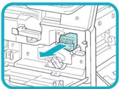
04
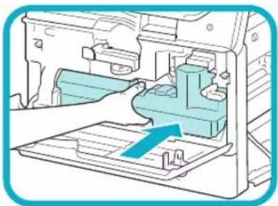
natural_image
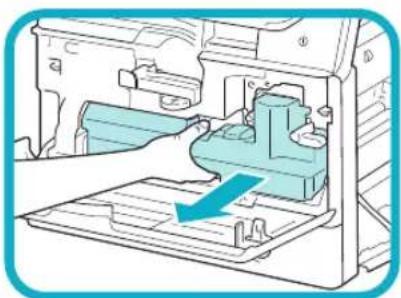
Diagram of a mechanical device interior showing internal components and a blue arrow indicating direction (no text or symbols present)Remove the waste toner container.
05
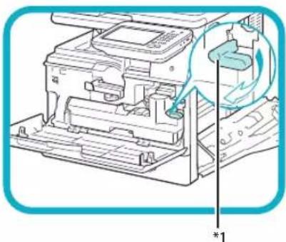
text_image
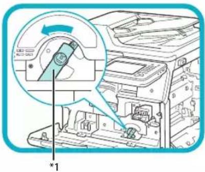
Technical diagram showing a mechanical device with a highlighted component and an arrow indicating direction, labeled with dimension marker *1.*1: Drum Unit Lock Lever
Turn the drum unit lock lever counterclockwise as far as it will go.
06
natural_image
Diagram of a mechanical device showing internal components with a blue arrow indicating a specific part (no text or symbols present)广力云
natural_image
Diagram showing three stages of a mechanical assembly with arrows indicating motion (no text or symbols)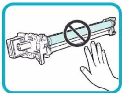
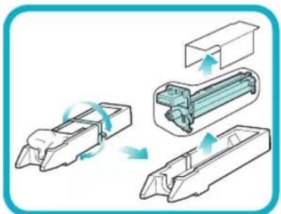
natural_image
Illustration of a hand blocking a cylindrical device with a prohibition symbol (no text or labels)Remove the cover attached to the drum insertion slot. The removed cover is not used later on.
Remove the drum unit from its protective bag.

IMPORTANT
Do not touch or expose the cylindrical, blue-green part to light • for a long time, as the print quality may deteriorate.
Do not expose the drum unit to direct sunlight or strong light. Condensation (water droplets on the inside or outside) may form on the drum unit when it is brought into an environment with a sudden change in temperature or humidity.
When moving a new drum unit to a location with change in temperature, leave the drum unit in the protective bag at the new location for two or more hours to allow it to adjust to the new temperature.
08

natural_image
Diagram of a mechanical device with motion arrows indicating movement, no text or symbols presentPull the two orange rings out and remove the protective cover.
09
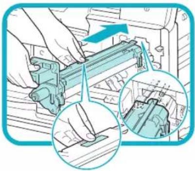
natural_image
Illustration of hands operating a mechanical device with two views showing internal components (no text or symbols)Holding the tab and the part with the blue marking, slowly insert the drum unit until it stops.
Make sure that the drum unit slides properly along the rails on the machine.
10
text_image
Diagram showing a device's internal components with a magnified view highlighting a component being inserted, labeled with part number *1.Turn the drum unit lock lever clockwise to its original position.
*1: Drum Unit Lock Lever
11
natural_image
Diagram of a mechanical device interior showing internal components and a blue arrow indicating direction (no text or symbols)Reinsert the removed waste toner container.
12
natural_image
Diagram of a printer or printer assembly with a paperclip and fan, showing internal components without any text or symbols.Turn the toner container lock lever clockwise to its original position.
*1: Toner Container Lock Lever
13
natural_image
Illustration of a hand pressing down on a computer interface with a blue arrow indicating action (no text or symbols present)Close the right cover.

CAUTION
Be careful not to get your fingers caught, as this may result in personal injury.
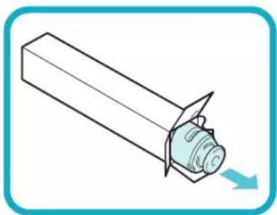
Installing the Toner Cartridge
text_image
01 *1*1: Toner Cartridge Lock Lever
Turn the toner cartridge lock lever counterclockwise so that the arrow marks on the lever and its axis face each other.
02
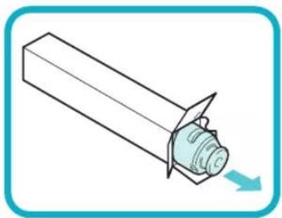
natural_image
Simple line drawing of a mechanical component with a curved arrow indicating direction (no text or symbols)Remove the toner cartridge from its protective bag.
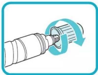
03
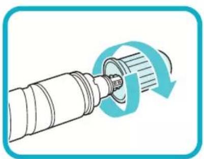
natural_image
Illustration of a mechanical component with a rotating arrow indicating rotation (no text or symbols)Remove the protective cap.
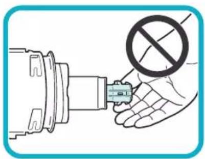
natural_image
Illustration of a hand holding a plug inserted into a mechanical component with a no-smoking symbol (no text or labels)
IMPORTANT
Do not touch the tip of the toner cartridge or subject it to shock by hitting it. Doing so may cause the toner cartridge to leak.
04

natural_image
Illustration of a hand inserting a device into a printer (no text or symbols visible)Insert the toner cartridge into the machine as far as it will go.
Support the new toner cartridge with your hand from underneath while pushing it into the machine with your other hand.
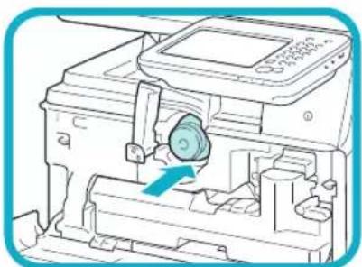
natural_image
Illustration of a printer's internal mechanism with a blue arrow indicating the process (no text or symbols present)05

text_image
Diagram showing a lock mechanism with directional arrows and a lock icon, labeled with an asterisk symbol.Turn the toner cartridge lock lever clockwise so that the arrow marks on the lever and its axis face each other.
*1: Toner Cartridge Lock Lever
06
text_image
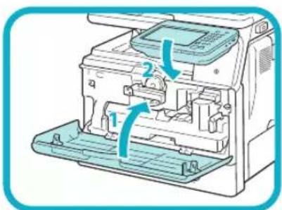
Diagram of a printer internal structure with labeled parts and directional arrows indicating assembly or movement.Close the front cover.
- Close the front cover of the main unit.
- Lower the control panel back in place.

CAUTION
Be careful not to get your fingers caught, as this may result in personal injury.
Loading Paper into the Paper Drawer
This section describes how to load plain paper into the paper drawer. If you load paper other than plain paper such as recycled paper, specify the type of paper loaded into the paper drawer. (See e-Manual > Settings/Registration.)
01
natural_image
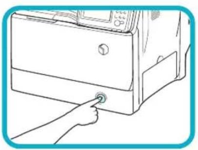
Line drawing of a hand pressing a button on a computer oven (no text or symbols)Press the open button on the paper drawer.
02
natural_image
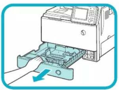
Illustration of a printer being inserted into a plastic case, with a hand adjusting the component (no text or symbols visible)Grip the handle, and pull out the paper drawer until it stops.
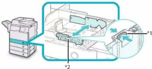
03
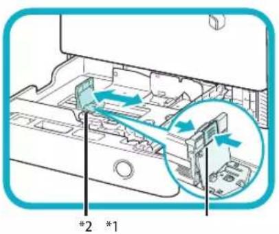
text_image
#2 *1Squeeze the lever on the side guide. Without releasing the lever, slide the side guide leftward or rightward to align it with the mark for the desired paper size.
*1: Lever
*2: Side Guide
04
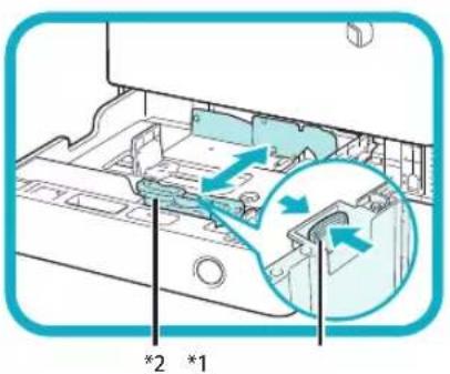
text_image
*2 *1Squeeze the lever on the front guide. Without releasing the lever, slide the front guide backward or forward to align it with the mark for the desired paper size.
*1: Lever
*2: Front Guide
05

natural_image
Illustration showing two hands folding a folded paper with a blue diagonal line (no text or symbols)Before loading paper, always fan the sheets several times, and align the edges to facilitate feeding.
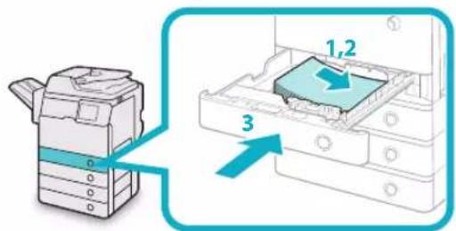
06
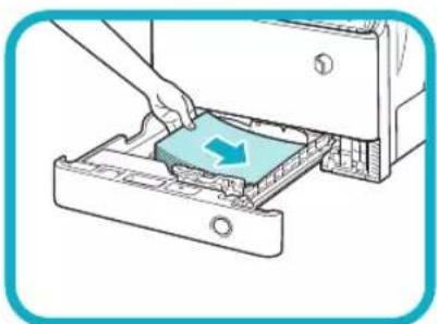
natural_image
Illustration of a hand inserting a plastic into a device into a housing (no text or symbols visible)Load the paper stack into the paper drawer.

CAUTION
When handling paper, take care not to cut your hands on the edges of the paper.

NOTE
Information on the paper loaded here will be registered later in the Setup Guide.
07
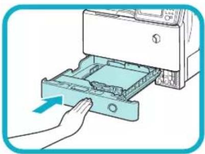
natural_image
Illustration of a hand inserting a printer into a plastic case (no text or symbols visible)Gently push the paper drawer back into the machine until it clicks into place in the closed position.

CAUTION
When returning the paper drawer to its original position, be careful not to get your fingers caught, as this may result in personal injury.
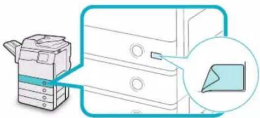
08
natural_image
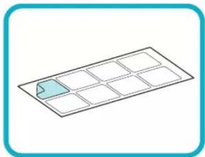
Simple line drawing of a grid with a highlighted rectangular cell (no text or symbols)Peel off the label for the loaded paper size and affix the label to the part of the paper drawer indicated in the illustration.
natural_image
Illustration of a printer with a magnified view of its cover (no text or symbols present)Attaching the Precaution Label
01
natural_image
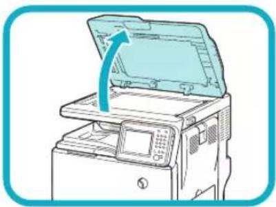
Illustration of a printer with an open lid and a blue arrow indicating the open lid (no text or symbols present)Open the feeder.
02
text_image
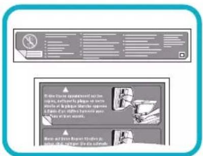
Scanned document page with Chinese text and two small illustrations of hands performing a task.Select the desired language label among the supplied precaution labels, peel off the label, then affix the label to the part indicated in the illustration.
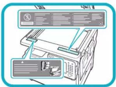
text_image
Diagram of a printer with labeled parts and UI elements, showing front panel layout and print options.On this part, the English label is already affixed. Affix your selected label over the existing label. If the desired language is English, you do not need to affix a new label.
03
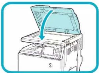
natural_image
Illustration of a printer with an open lid and a blue arrow indicating the process (no text or symbols present)Gently close the feeder.

CAUTION
Close the feeder gently to avoid catching your hands, as this may result in personal injury.
Connecting the Power Cord
For Users with the Optional Finisher:
See the installation manual supplied with the optional finisher to attach the finisher to the machine, then connect the power cord.
01
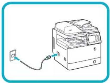
natural_image
Line drawing of a printer connected to a power outlet (no text or symbols)Connect the power cord to the socket on the left side of the machine and to the wall outlet.
Setting and Registering the Machine
2
Main Power and Energy Saver Key.... 24
How to Turn ON the Main Power 24
Energy Saver Key 25
Shutting Down the Machine 25
Using the Setup Guide to Configure the Machine.... 26
Changing Specified Settings 33
Main Power and Energy Saver Key
This section describes how to use the main power switch and the Energy Saver key.
How to Turn ON the Main Power
This section explains how to turn ON the main power.

IMPORTANT
If you want to turn OFF the main power and then back ON again, wait for at least 10 seconds after the main power indicator is turned OFF before turning ON the main power. However, when [Quick Startup Settings for Main Power] is enabled, if you do not wait more than 20 seconds after the main power indicator is turned OFF, quick startup is not performed.
Make sure that the power plug is firmly inserted into the power outlet.
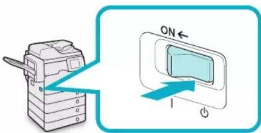
01

WARNING
Do not connect or disconnect the power cord with wet hands, as this may result in electrical shock.
Press the main power switch (located on the left side of the machine) to the "l" side.
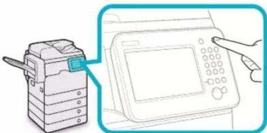
02
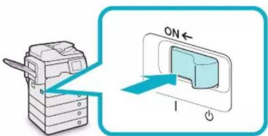
text_image
ON 1The main power indicator on the control panel lights when you turn ON the main power switch.
Various screens appear when system software is loading.
If you are using a login service, log in using the procedure for the login service you are using.

NOTE
You can change the default display that appears • after the machine is turned ON from [Default Screen after Startup/Restoration] on the Settings/Registration screen. (See e-Manual > Settings/Registration.)
If this machine is connected to a powered off • Macintosh computer by USB cable, the computer may turn on automatically when this machine does. In this case, disconnect the USB cable from the machine. You may also be able to solve this problem by using a USB hub between the machine and the Macintosh.
The response of the buttons and keys may not be optimal immediately after you turn ON the main power of the machine.
If you set [Quick Startup Settings for Main Power] to • 'On' in [Preferences] (Settings/Registration), the tone sounds when turning ON the main power of the machine. (Depending on the situations, the machine does not startup quickly and the tone does not sound.)
Depending on the conditions under which the machine is being used, the machine may not startup quickly if you set [Quick Startup Settings for Main Power] to 'On'. For more information, see e-Manual > Settings/Registration.
If you are using Department ID Management with the Copy Card Reader-F1, see e-Manual > Optional Products/Software.
If you are using Department ID Management, see e-Manual > Basic Operations.
If you are using SSO-H, see e-Manual > Basic • Operations.
Energy Saver Key
You can press (Energy Saver) to make the machine enter the Sleep mode and reduce power consumption. If the machine is idle for a certain period of time, the machine will enter the Auto Sleep mode to minimize energy consumption.
Press 📄 (Energy Saver) to cancel the Sleep mode and resume normal machine operations.
natural_image
Illustration of a printer next to a digital device with a hand pointing at it (no text or symbols present)
NOTE
The machine can receive and print documents from a personal computer when it is in the Sleep mode. I-fax and fax documents can also be received while the machine is in the Sleep mode.
Shutting Down the Machine
This machine performs a procedure to protect the memory when the machine is shut down.
This enables the machine to be shut down safely, even if there are any jobs being processed, or a MEAP application is running while the machine is shutting down.
To safely turn OFF the machine's main power, press the main power switch (located on the left side of the machine) to the "↓" side.
01
text_image
Diagram showing a printer with an ON/OFF switch and its screen, illustrating the process of device operation.
IMPORTANT
Do not turn the main power OFF while using the • Fax/I-Fax function. Sending or receiving I-fax or fax documents cannot be done when the main power is turned OFF.
The machine may take some time to completely • shutdown. Do not unplug the power cord until the main power indicator of the machine is OFF. If the main power is turned OFF during scanning • or printing, a paper jam may occur.

NOTE
You can shut down the machine from the Remote UI using the Remote Shutdown mode. For more information, see e-Manual > Remote UI. If you set [Quick Startup Settings for Main Power] to 'On' in [Preferences] (Settings/Registration), the tone sounds when turning OFF the main power of the machine. (Depending on the situations, the machine does not startup quickly and the tone does not sound.)
Using the Setup Guide to Configure the Machine
When the power is turned ON for the first time after installing the machine, the Setup Guide screen is displayed.
It is recommended that you follow the instructions that appear on the touch panel display to configure the machine.

NOTE
- You can restart the Setup Guide from [Start Setup Guide] (Settings/Registration) > [Management Settings] > [License/Other]).
You can change settings registered in the Setup Guide from the items in Ⓧ (Settings/Registration). For more information, see "Changing Specified Settings" on p. 33. - For most settings in the Setup Guide, you can move to the next setting even without entering anything. Unset items can be set separately. You can set them after finishing the Setup Guide.
You cannot exit the Setup Guide until it is finished. - If the power is turned OFF while using the Setup Guide, when you turn the power back ON, the Setup Guide is automatically started. Perform Setup Guide settings once again.
- Once the Setup Guide has been completed, it will not start up again when turning ON the machine.
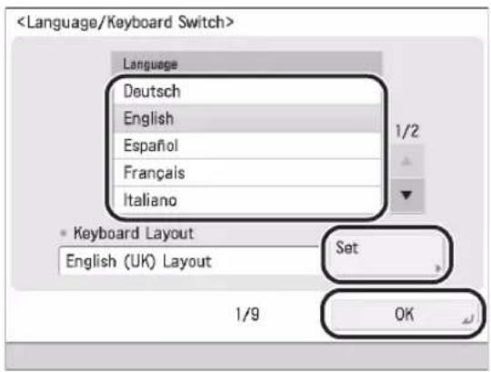
Configuring the Touch Panel Display's Language and Keyboard Layout 01
- Set the language and keyboard layout → press [OK].
text_image
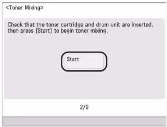
Mixing the Toner02
Mixing the toner will take a maximum of seven minutes to complete. Until toner mixing is completed, you cannot move on to the next step.
- Press [Start].
text_image

text_image
After the toner finishes mixing, press [OK].
Registering the Paper Information That Was Loaded When Installing the Machine
- Select the paper source that you want to load the paper type for → press [Set].
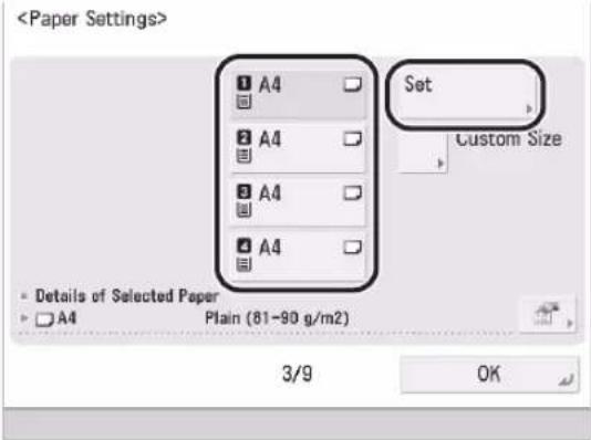
text_image
- Select the paper type → press [OK].
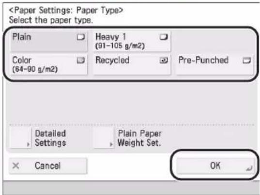
text_image
If you select [Plain], you can select the paper weight from [Plain Paper Weight Set.].
If there is no button for the loaded paper, press [Detailed Settings] → select the paper type from the detailed setting screen.
03
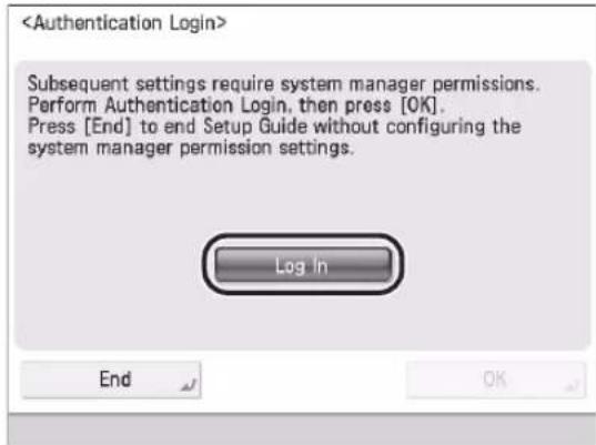
Logging In04
In order to continue on with network settings, date/time, and fax settings, it is necessary to log in as an administrator.
To end setting configuration here, press [End] and see step 15.
- Press [Log In] → enter the authentication information → press [Log in] → [OK].
text_image
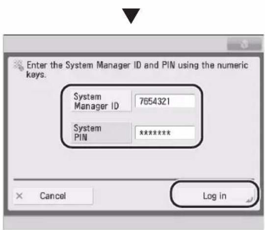
text_image
Enter the System Manager ID and PIN using the numeric keys. System Manager ID 7654321 System PIN ******** Cancel Log inIMPORTANT
The default setting for both the System Manager ID and System PIN is '7654321'. After installing the machine, when logging in for the first time, enter '7654321' for both the System Manager ID and System PIN.
Setting the Date and Time05
- Select the time zone from the
- Enter the current date and time using Ⓞ - (numeric keys) → press [OK].
umeric keys) → press [OK].


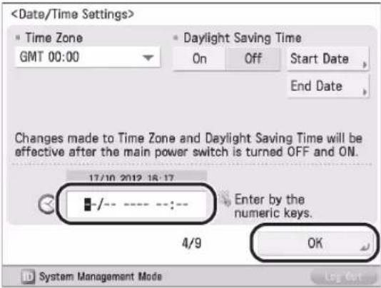
text_image
Enter the day and the month using four digits (including zeros). The time is displayed in 24-hour notation.
Examples:
May 6 → 0605
7:05 a.m. → 0705
11:18 p.m. → 2318
If you make a mistake when entering values, press ⓒ (Clear) → enter the values again, starting with the day.

NOTE
The standard time zones of the world are expressed globally in terms of the difference in hours (± up to 12 hours) from GMT (± 0 hours). A time zone is a region throughout which this time difference is the same.
If you set Daylight Saving Time, specify both the starting and ending date in [Start Date] and [End Date]. The machine automatically sets the standard time of the machine one hour forward at the specified date and time.
Setting an IP Address 06
You can perform the following settings in order to connect to and use a TCP/IP network with the machine. Set IPv4 here.
- Set
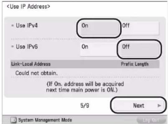
text_image
- Specify each setting → press [OK].
For manual entry: ●
When the network administrator connects to a network where each machine has a fixed IP assigned to it, the IP address must be set manually.
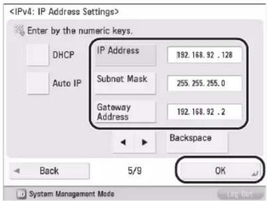
text_image
If you do not know the IP, contact your administrator.
To enable DHCP ●
When connecting to a network where each machine's IP address is automatically assigned to it by DHCP, set
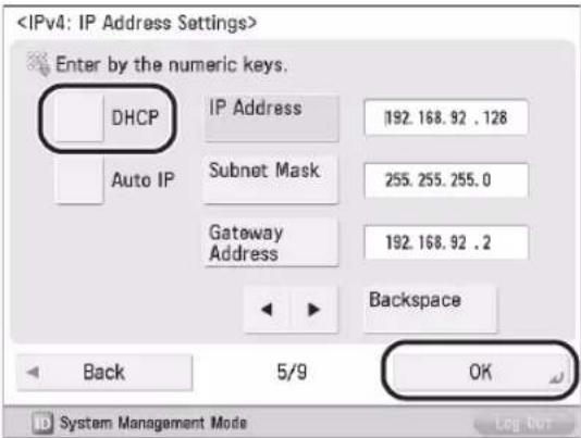
text_image

NOTE
By setting
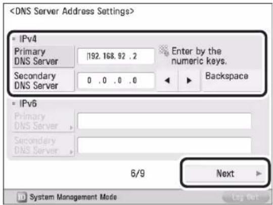
Setting the DNS Server07
DNS is the abbreviation of Domain Name System, and is the function that binds an IP address and a name (in this machine, host name). By setting the DNS server address for this machine, when accessing this machine through the network, this machine is accessed not by IP address but by a name such as "iR-ADV XXXX."
When using DHCP, the IP address may change, so it is necessary to update IP addresses bound to names. In these cases, it is necessary to configure "Dynamic Update" to update the links between IP addresses and names.
A dynamic DNS server is required to use DNS Dynamic Update.
This section describes how to specify the IPv4 settings.
- Specify the following settings in
→ press [Next].
text_image
To enable DNS Dynamic Update: ●
Enter the DNS server IPv4 address in [Primary DNS Server].
To disable DNS Dynamic Update: ●
Enter [Primary DNS Server] and [Secondary DNS Server].

NOTE
Secondary DNS Server:
The substitute DNS server that is used when the primary DNS server cannot be used. If you do not want to set the secondary DNS server, enter '0.0.0.0'. When using DNS Dynamic Update, setting this is not necessary.
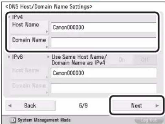
- Enter the [Host Name] and [Domain Name] for
→ press [Next].
text_image
[Host Name]:
The name that appears on the network (the machine's name, etc.)
[Domain Name]:
The network domain that this machine belongs to
3. Specify for → press [OK].
![CANON imageRUNNER ADVANCE 400i - Specify for → press [OK]. - 1](/content/2026/04/666717/images/ddd7aab37f21f97143d5a40c56037fecc5528e488152273f1bc08c0fd0fe6765.jpg)
text_image
By setting
Setting the Proxy Server08
If accessing the internet or other external network through a proxy server from this machine, these settings are required.
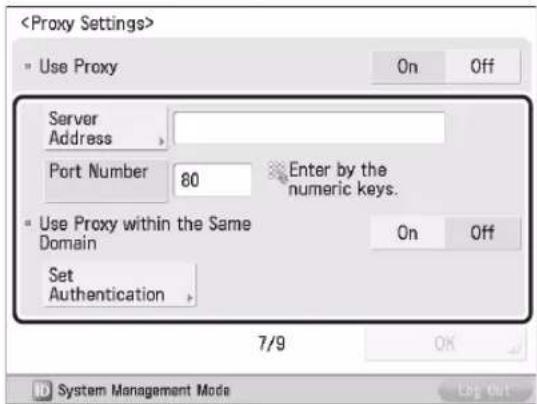
text_image
[Server Address]:
Enter the IP address of the proxy server or the path of the server (i.e., starfish.company.com).
[Port Number]:
Enter the port number of the proxy server.
If using the proxy within the same domain, press [On].
[Set Authentication]:
If authentication is required when accessing an external network through a proxy server, enter the user name and password registered on the server.
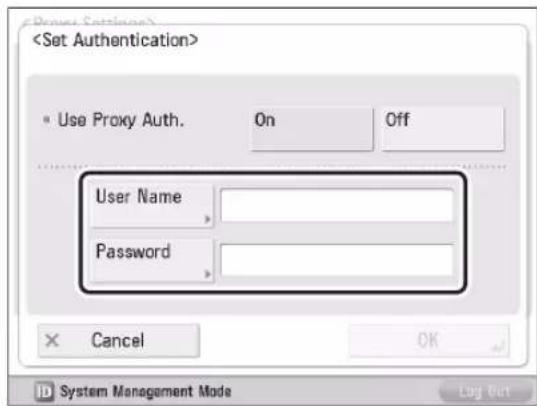
text_image
[User Name]:
Enter the user name for the proxy authentication.
[Password]:
Enter the password for the proxy authentication.
If a fax board is installed on the machine, proceed to "9. Setting Country/Region."
If a fax board is not installed on the machine, proceed to "13. Specifying the System Manager Settings."
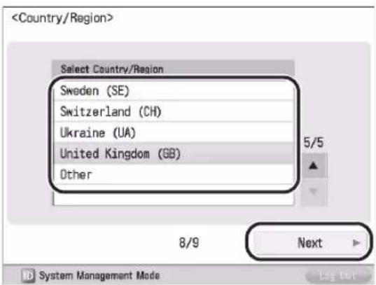
Setting Country/Region09
- Select the country/region where the machine is located → press [Next].
text_image
IMPORTANT
This setting is necessary to specify the fax line settings. This setting can only be carried out in the Setup Guide.
Registering Your Machine's Fax Number 10
This section describes how to register the fax number your machine uses when sending faxes. This number is printed on the document that you fax to the receiving party.
1. Enter the fax number → press [Next].
![CANON imageRUNNER ADVANCE 400i - Enter the fax number → press [Next]. - 1](/content/2026/04/666717/images/0863aee261874c907c0baaf898d8788c38d3e356b683c34e46f450bc1491e1e0.jpg)
text_image
Registering the Unit Name 11
The unit's name appears on the receiving party's fax machine, or is printed on the received document as the Sender Name. You can register the name of your company or department as the unit name.
1. Press [Set] → enter the unit name → press [Next].
![CANON imageRUNNER ADVANCE 400i - Press [Set] → enter the unit name → press [Next]. - 1](/content/2026/04/666717/images/9ce6333ab30a5d12232ebf51566c9dfc19166227d8928473ad607d8f4866c775.jpg)
text_image
Setting the Line Type 12
You can set the phone line type to use for sending.
1. Select the line type → press [OK].
![CANON imageRUNNER ADVANCE 400i - Select the line type → press [OK]. - 1](/content/2026/04/666717/images/95610044d87ad0a0689afb9dacb0a7f26b6ea59d0ce0c484b0673ccc5fe9c13b.jpg)
text_image
Specifying the System Manager 13 Settings
You can register the System Manager Information settings.
1. Change the authentication information → press [Next] → enter information if necessary → press [OK].
![CANON imageRUNNER ADVANCE 400i - Change the authentication information → press [Next] → enter information if necessary → press [OK]. - 1](/content/2026/04/666717/images/5b7cf2429a34cd56bf9f59972085b9c473a512210cb03600eccceec3cc73c73a.jpg)
text_image
![CANON imageRUNNER ADVANCE 400i - Change the authentication information → press [Next] → enter information if necessary → press [OK]. - 2](/content/2026/04/666717/images/e92d5bc88a536d7fd5292010fdb4b0d29776d6979e151133190849b1d5ae66cc.jpg)
text_image
![CANON imageRUNNER ADVANCE 400i - Change the authentication information → press [Next] → enter information if necessary → press [OK]. - 3](/content/2026/04/666717/images/dfc2b78b9401c637fec38bc3552f258e5f10bae4f41baa10cd54dd95fbe2d23e.jpg)
IMPORTANT
The default setting for both the System Manager ID and System PIN is '7654321'. Make sure to change these settings.
Recalibrating the Gradation and 14 Density Settings of the Machine Precisely
The procedure involves making test pages and placing them on the platen glass for scanning. Once this is complete, the machine automatically corrects the irregularities.

IMPORTANT
Three test pages are output by the machine during this adjustment.
- Press [Both].
- Select the paper source → press [OK].
- Press [Start Printing].
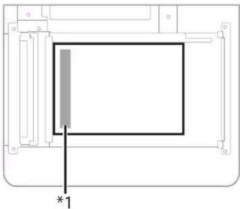
- Place the first test page on the platen glass → press [Start Scanning].
natural_image
Pure technical diagram of a mechanical component with no text, numbers, or symbols*1 Place the test page face down on the platen glass, with the black band along the left edge of the platen glass
- Remove the first test page from the platen glass → press [Start Printing].
- Repeat steps 4 and 5 two more times.
- Remove the third test page from the platen glass.
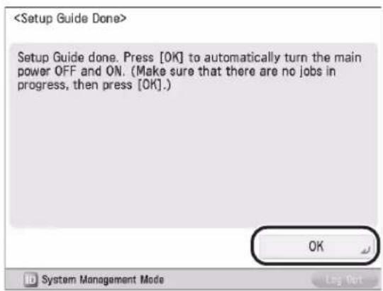
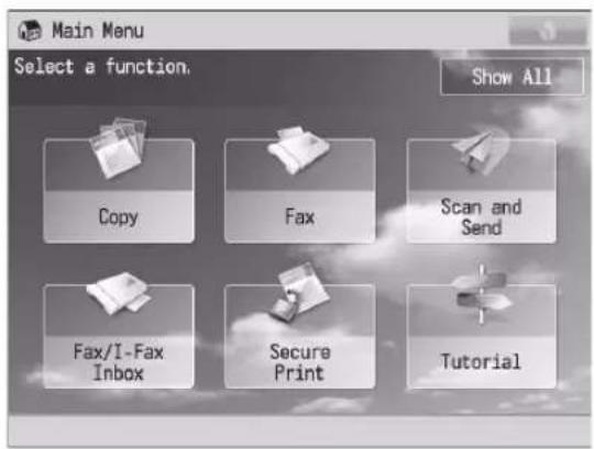
Closing the Setup Guide 15
Closing the Setup Guide by pressing [OK] causes the machine to restart.
After the restart, the main menu is displayed and you can use the machine.
text_image

text_image
Main Menu Select a function. Show All Copy Fax Scan and Send Fax/I-Fax Inbox Secure Print TutorialChanging Specified Settings
You can change settings registered in the Setup Guide from the items in (Settings/Registration). From [Start Setup Guide] (Settings/Registration), you can start the Setup Guide and redo all the settings from the beginning. (See e-Manual > Security.)
For more information on changing the settings, see the following.
| Setting Description Location in e-Manual | |
| Language, keyboard layout Settings | /Registration > Preferences > Display Settings > Changing the Display Language/Keyboard on the Touch Panel Display |
| Information on the paper loaded in the paper source | Settings/Registration > Preferences > Paper Settings > Registering the Paper Size and Type for a Paper Source |
| Date/time Settings/Registration > | Preferences > Timer/Energy Settings > Current Date and Time |
| Network settings, DNS server settings | When setting IPv4: Network > TCP/IP Network Setup Procedures > Protocol Settings > TCP/IPv4 SettingsWhen setting IPv6: Network > TCP/IP Network Setup Procedures > Protocol Settings > TCP/IPv6 Settings |
| Proxy Settings Network > TCP/IP Net | Network Setup Procedures > Protocol Settings > Settings Common to TCP/IPv4 and TCP/IPv6 |
| Fax number of the machine Settings | /Registration > Function Settings > Send > Specifying the Fax Settings > Fax Line Settings |
| Unit name of the machine | |
| Telephone line type | |
| System Manager Settings Security > | Restricting Access by Authentication > Specifying the System Manager Settings |

NOTE
To change [Country/Region], you must change it from [Start Setup Guide] (Settings/Registration).
Before Using This Machine
3
Parts and Their Functions .... 36
External View 36
Internal View.... 37
Feeder 37
Control Panel Parts and Functions.... 38
Backing Up/Exporting Data 40
Parts and Their Functions
This section provides you with the names and functions of all the parts of the machine.
For more information on optional products, parts and their functions, see e-Manual > Optional Products/Software.
External View
This section contains an external view of the imageRUNNER ADVANCE 500i.
When the Cassette Module-AA1 and Staple ● Finisher-R1 Are Attached:
text_image
Diagram of a printer with labeled parts including a door panel, printer, and printer unit, showing internal components and connection points.When the Cassette Module-AA1 Is Attached: ●
text_image
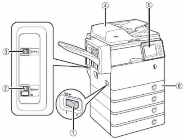
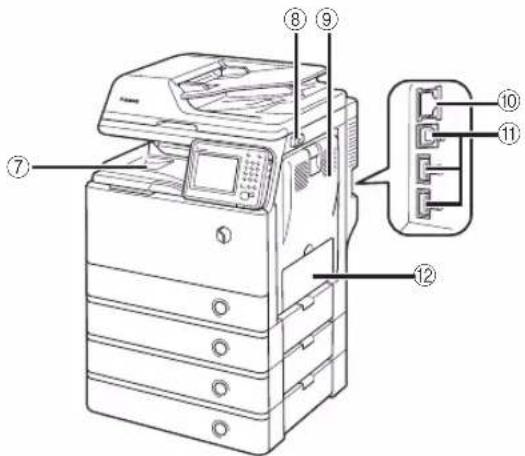
Technical diagram of a printer with numbered parts and internal connector labels1 Main Power Switch
Press to the "I" side to turn ON the machine.
2 LINE 1
Use this port to connect a fax line to the machine.
3 LINE 2
Use this port to connect the Super G3 2nd Line Fax Board to the machine.
4 Feeder
Originals placed in the feeder are automatically fed sheet by sheet to the scanning area. The feeder also automatically turns over two-sided originals to make one- or two-sided copies.
5 Control Panel
The control panel includes the keys, touch panel display, and indicators required for operating the machine. (See "Control Panel Parts and Functions," on p. 38.)
6 Paper Drawer 1
Paper Drawer 1 holds up to 550 sheets of paper (80 g/m ^2 ).
7 Output Tray
Prints are output to this tray if the optional Staple Finisher-R1 is not attached.
8 USB Port (1)
Use the USB port to connect USB memory, external hard disks, and other devices to the machine.
9 Right Cover of the Main Unit
Open this cover when clearing a paper jam inside the main unit. (See e-Manual > Problem Solving.)
10 LAN Port
Use an Ethernet cable to connect the machine to a network.
11 USB Port (2)
Use the USB port to connect external hard disks and other devices to the machine. You can also connect the machine to a computer using a USB cable.
12 Multi-Purpose Tray
Use the multi-purpose tray to feed paper manually, and for loading nonstandard paper stock, such as envelopes. (See e-Manual > Basic Operations.)
Internal View
This section contains an external view of the imageRUNNER ADVANCE 500i.
When the Cassette Module-AA1 and Staple ● Finisher-R1 Are Attached:
text_image
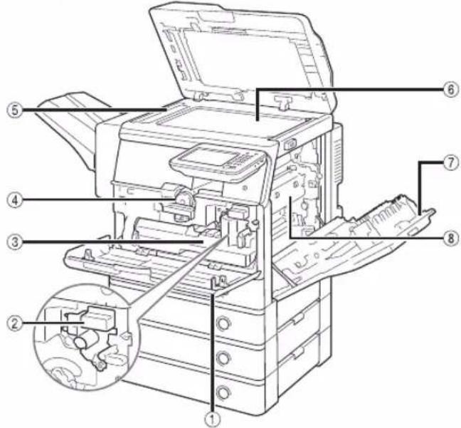
Technical diagram of a printer with numbered parts for identification and assembly reference1 Front Cover of the Main Unit
Open this cover to replace the toner cartridge, the waste toner container, and the drum unit.
2 Drum Unit
The unit that applies toner to paper during printing. For more information on handling the drum unit, see the "Drum Unit Replacing Guide."
3 Waste Toner Container
When the waste toner container becomes full, replace it with a new one. (See "Replacing the Waste Toner Container," on p.47.)
4 Toner Cartridge
When toner runs out, pull out the toner cartridge and replace it with a new one. (See "Consumables," on p.57.)
5 Scanning Area
Originals placed in the feeder are scanned here.
6 Platen Glass
Place originals here when scanning books, heavyweight originals, transparencies, etc.
7 Right Cover of the Main Unit
Open this cover when clearing a paper jam inside the main unit.
8 Fixing Unit
If paper is jammed in the fixing unit, remove the jammed paper carefully.
Feeder
text_image
① ② ③ ④ Cane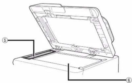
text_image
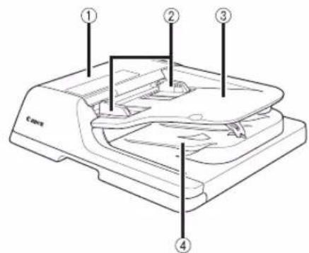
Technical diagram of a printer with labeled parts, showing open lid and internal structure1 Feeder Cover
Open this cover to remove jammed paper.
2 Slide Guides
Adjust these guides to match the width of the original.
3 Original Supply Tray
Originals placed here are automatically fed sheet by sheet into the feeder. Place originals into this tray with the surface that you want to scan face up.
4 Original Output Area
Originals that have been scanned from the original supply tray are output into the original output area.
5 Document Feed Scanning Area
Scans documents sent from the feeder.
6 Platen Glass
Use the platen glass when scanning books, thick originals, thin originals, transparencies, etc.
Control Panel Parts and Functions
text_image
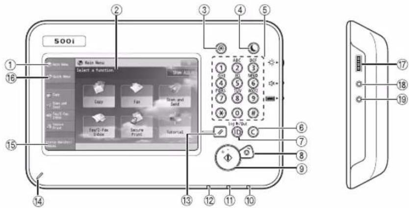
500i 1 2 3 4 5 6 7 8 9 10 11 12 13 14 15 16 Auto Menu Select a Function Show ALL Copy Fas Store and Send Fas/Can Show Secure Print Tutorial Logic Button Logic Button Logic Button Logic Button Logic Button Logic Button Logic Button Logic Button Logic Button Logic Button Logic Button Logic Button Logic Button Logic Button Logic Button Logic Button Logic Button Logic Button Logic Button Logic Button Logic Button Logic Button Logic Button Logic Button Logic Button Logic Button Logic Button Logic Button Logic Button Logic Button Logic Button Logic Button Logic Button Logic Button1 [Main Menu]
Press to display the Main Menu screen. If the Main Menu screen is not displayed when using a function, it is necessary to press [Main Menu] before using the function.
2 Touch Panel Display
The settings screen for each function is shown on this display. Six function keys are displayed by default.
3 Settings/Registration key
Press to specify settings/registration.
4 Energy Saver key
Press to set or cancel the Sleep mode. Lights when the machine enters the Sleep mode.
5 Numeric keys
Press to enter numerical values.
6 Clear key
Press to clear entered values or characters.
7 ID (Log In/Out) key
Press to log in/out when a login service such as Department ID Management or SSO-H has been set.
8 Stop key
Press to stop a job in progress, such as a scan, copy, or fax (scanning only) job.
9 Start key
Press to start an operation.
10 Main Power Indicator
Lights when the main power is turned ON.
11 Error Indicator
Flashes or lights if there is an error in the machine. When the Error indicator flashes, follow the instructions that appear on the touch panel display. When the Error indicator maintains a steady red light, contact your local authorized Canon dealer.
12 Processing/Data Indicator
Flashes or blinks green when the machine is performing operations, and maintains a steady green light when fax data is stored in memory.
13 Reset key
Press to restore the standard settings of the machine.
14 Edit Pen
Use when operating the touch panel display, such as to enter characters.
15 [Status Monitor/Cancel]
Press to check the status of jobs or to cancel print jobs. Also, you can check the status of the machine such as the amount of paper remaining in the paper source.
16 [Quick Menu]
Press to display functions registered in the Quick Menu.
17 Brightness Adjustment Dial
Use to adjust the brightness of the touch panel display.
18 Volume Settings key
Press to display the screen for adjusting settings, such as the transmission volume and fax sending/receiving alarm volume.
19 Counter Check key
Press to display the copy and print count totals on the touch panel display.
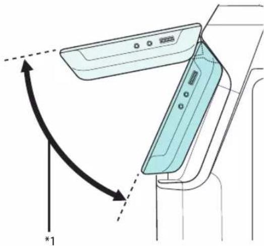
Adjusting the Angle of the Control Panel
The angle of the control panel is adjustable as shown below.
natural_image
Diagram of a device with a curved arrow and label *1, showing no readable text or symbols.*1: Adjustable Range

IMPORTANT
Do not apply excess force to the control panel when adjusting its angle.
Backing Up/Exporting Data
Various data such as the received data, address book, and Settings/Registration settings are stored on the internal memory of the machine.
A malfunction in the memory may cause these data to be lost. Please regularly back up/export your important data.
Please note that Canon will not be held responsible for any damages caused by the loss of data.
You can backup/export data in the following ways:
Import/Export All•
Import/Export Individually•
You can back up/export the following data:
Data You Can Import/Export All
You can save/load multiple items at once. In addition, you can exchange data with this machine and other machines which support the Import/Export All function.

IMPORTANT
You cannot use the Import All function, depending on the recipient's machine model. For more information, contact your local authorized Canon dealer.
| Data References | |
| Settings/Registration Basic Information | e-Manual > Remote UI |
| Paper Type Management Settings | |
| Forwarding Settings | |
| Box Settings | |
| Department ID Management Settings | |
| Main Menu Settings | |
| Web Access Settings | |
| Favorite Settings | |
| Address Book | |
| Quick Menu Settings | |
| MEAP Application Setting Information | |
| User Setting Information |
Data You Can Import/Export Individually
You can save/load data individually. In addition, you can exchange data with this machine and other machines which do not support the Import/Export All function.
| Data References | |
| Address Lists | e-Manual > Remote UI |
| Device Settings(Forwarding Settings,Address Book, SendFunction Favorite Settings) | |
| Printer Settings | |
| Paper Information | |
| Web Access Favorites e-Manual | > Web Access |
Other Data You Can Import/Export
You can exchange data with this machine and other machines which do not support the Import/Export All function.
| Data References | ||
| Quick Menu Information | e-Manual > Quick Menu | |
| Data Relating to MEAP | License files for MEAP applications | e-Manual > MEAP |
| Data saved from MEAP applications*1 | Instruction manuals for each MEAP application. | |
| User authentication information registered for the Local Device Authentication system of SSO-H (Single Sign-On H) | e-Manual > MEAP | |
*1 You may be able to back up data stored by MEAP applications, depending on the application.

NOTE
The passwords and PIN are backed up at the same time. However, some of the passwords may not be backed up, depending on the type of the password. If your machine is not connected to a network, it is recommended that you print and store important information such as the Address Book. (See e-Manual > Basic Operations.)
Routine Maintenance
4
Loading Paper....42
Loading Paper into a Paper Drawer 42
Adjusting a Paper Drawer to Hold a Different Paper Size.... 43
Replacing the Toner Cartridge/Waste Toner Container 45
Replacing the Toner Cartridge.... 45
Replacing the Waste Toner Container 47
Replacing the Drum Unit 50
Routine Cleaning....54
Cleaning the Platen Glass and Underside of the Feeder 54
Manual Feeder Cleaning 54
Consumables....57
When an Error Message/Error Code Is Displayed.... 59
When an Error Message Is Displayed.... 59
When an Error Code Is Displayed.... 59
Service Call Message 60
Contacting Your Local Authorized Canon Dealer 60
Setting the Limited Functions Mode from the Service Call Message Screen.... 61
Functions Available When the Printer/Scanner Cannot Be Used Due to an Error.... 61
Locations of Staple/Paper Jams 63
Loading Paper
This section describes how to load paper.
Loading Paper into a Paper Drawer
If the selected paper runs out, or the selected paper drawer runs out of paper during printing, a screen prompting you to load paper appears on the touch panel display.
You can follow the procedure below to load paper into the paper drawers.

CAUTION
When handling paper, take care not to cut your hands on the edges of the paper.

IMPORTANT
A screen prompting you to load paper also • appears if the selected paper drawer is not fully inserted into the machine. Make sure that the paper drawer is properly in place.
Do not load the following types of paper into the • paper drawers. Doing so may cause a paper jam.
Severely curled or wrinkled paper -
Thin straw paper -
Paper which has been printed on using a thermal - transfer printer
The reverse side of paper which has been printed - on using a thermal transfer printer
Fan the stack of paper well before loading it. Paper such as recycled paper, pre-punched paper, and heavy paper should be fanned particularly well before loading it.
Never place paper or any other items in the empty part of the drawer next to the paper stack. Doing so may cause paper jams.
When you are printing in the Staple mode, do not remove the output sheets that are waiting to be stapled. (Printing and stapling resume after you clear the paper jam.)

NOTE
The following paper sizes can be loaded into Paper • Drawers 1, 2, 3, and 4:
Paper Drawers 1, 3, and 4: A4 and A5 -
Paper Drawer 2: A4, A5, and envelopes -
Envelopes can be loaded into Paper Drawer 2 only if the Envelope Cassette-E1 is attached.
Paper drawers 2, 3, and 4 can be used when the optional Cassette Module-AA1 is attached to the machine.
- If a message prompting you to load paper appears during printing, the remaining prints are automatically made after you load the correct paper. If you select a different paper drawer, the remaining prints are made after you press [OK].
- Press [Cancel] to cancel printing.
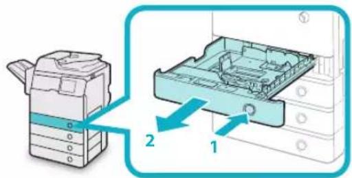
01 Open the paper drawer.
text_image
Diagram showing a printer device with labeled parts and directional arrows indicating assembly or process flow.-
Press the open button on the paper drawer in which you want to load paper.
-
Grip the handle, and pull out the paper drawer until it stops.
02 Prepare the paper to load.

natural_image
Illustration showing two hands folding a folded paper with a blue diagonal line (no text or symbols)Open the packaging for the paper and remove the paper stack.

NOTE
For high-quality printouts, use paper recommended by Canon.
- Before loading paper, always fan the sheets several times, and align the edges to facilitate feeding.
Load the paper stack into the paper 03 drawer.
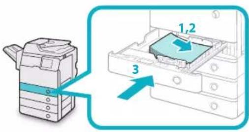
text_image
Diagram showing a printer device with labeled parts and directional arrows indicating assembly or operation.- Make sure that the paper size setting of the paper drawer matches the size of the paper to load in the paper drawer.
- Load the paper stack against the right wall of the paper drawer.
- Gently push the paper drawer back into the machine until it clicks into place in the closed position.

CAUTION
When returning the paper drawer to its original position, be careful not to get your fingers caught, as this may result in personal injury.

IMPORTANT
Paper which is curled must be straightened out • before loading it into the paper drawer.
You will not be able to make copies or print if you load paper that exceeds the loading limit mark (☑), or if the paper drawer is not completely pushed into the machine.
Make sure that the height of the paper stack does not exceed the loading limit mark (###).
Always check that the paper drawers are in place.

NOTE
Each paper drawer holds about 550 sheets of paper · (80 g/m²).
If there are instructions on the paper package about which side of the paper to load, follow those instructions.
When the paper is loaded into the paper drawer, the side facing up is the one printed on.
If problems, such as poor print quality or paper jams occur, try turning the paper stack over and reloading it.
For more information on the print direction of • preprinted paper (paper which has logos or patterns already printed on it), see e-Manual > Copy.
Rewrap any remaining paper in its original package, and store it in a dry place, away from direct sunlight.
If paper runs out and printing is stopped, load a new paper stack. Printing restarts after the new paper stack is loaded.
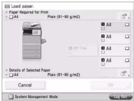
text_image
Load paper. Paper Required for Print A4 Plain (81-90 g/m2) 1 A4 2 A4 3 A4 4 A4 5 MF Tray 6 A4 Details of Selected Paper A4 Plain (81-90 g/m2) Cancel OK System Management Mode Log OutIf you print on the paper which has absorbed • moisture, steam may come out from the output area of the machine. This is because the moist on the paper evaporates when the high temperature is applied when a toner is fixed to the paper. It is not a malfunction. (This especially happens in low room temperature.)
Adjusting a Paper Drawer to Hold a Different Paper Size
If you want to load a different size paper into a paper drawer, you can follow the procedure described below to adjust the paper drawer guides.

CAUTION
When handling paper, take care not to cut your hands on the edges of the paper.
Remove the paper loaded in the paper 01 drawer.
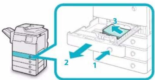
text_image
Diagram showing printer internal structure with labeled parts 1, 2, and 3, illustrating a printer's internal components.-
Press and release the button on the paper drawer in which you want to adjust.
-
Grip the handle, and pull out the paper drawer until it stops.
-
Remove all of the remaining paper.
Adjust the position of the Side Guide.02
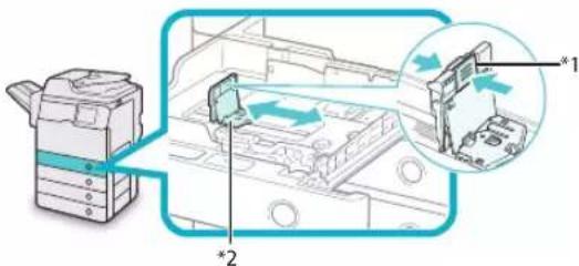
text_image
Diagram illustrating a printer's internal structure with labeled components and directional arrows indicating movement or assembly.*1: Lever
*2: Side Guide
- Squeeze the lever on the side guide.
- Without releasing the lever, slide the side guide leftward or rightward to align it with the mark for the desired paper size.
Adjust the position of the Front Guide.03
text_image
Diagram showing a printer's internal structure with labeled components, including a zoomed-in view of the component.*1: Lever
*2: Front Guide
- Squeeze the lever on the front guide.
- Without releasing the lever, slide the front guide backward or forward to align it with the mark for the desired paper size.

IMPORTANT
Adjust the guides correctly. Failure to do so may cause paper jams or dirty prints, or make the inside of the machine dirty.
Load the appropriate size paper into 04 the paper drawer.
text_image
Diagram showing a printer with labeled parts and an arrow indicating assembly or transformation, including numbers 1,2 and 3.- Make sure that the paper size setting of the paper drawer matches the size of the paper to load in the paper drawer.
- Load the paper stack against the right wall of the paper drawer.
- Gently push the paper drawer back into the machine until it clicks into place in the closed position.

CAUTION
When returning the paper drawer to its original position, be careful not to get your fingers caught, as this may result in personal injury.
Place the appropriate paper size label 05 on the paper drawer.
natural_image
Illustration of a printer next to a computer with a magnified view of the printer's cover (no text or symbols present)
IMPORTANT
The paper sizes marked on the labels may include sizes that the machine is unable to use.
Specify the paper type as required.06
For more information on registering the paper size and type, see e-Manual > Settings/Registration.

IMPORTANT
Make sure that the paper type setting of the paper drawer matches the type of the paper that is being loaded.
Replacing the Toner Cartridge/Waste Toner Container
Replacing the Toner Cartridge
When the message
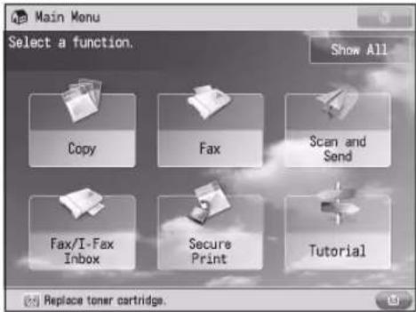
text_image
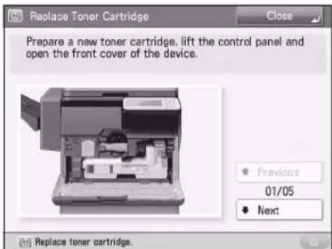
Main Menu Select a function. Show All Copy Fax Scan and Send Fax/I-Fax Inbox Secure Print Tutorial Replace toner cartridge.When the toners run out completely and prints can no longer be made, a screen with instructions on how to replace the toner cartridge appears on the touch panel display. Follow the procedure described below to replace the toner cartridge.
If you press [Close], you can continue operations, such as setting modes and scanning originals, even if you do not replace the toner cartridge immediately.
text_image
Replace Toner Cartridge Prepare a new toner cartridge, lift the control panel and open the front cover of the device. Previous 01/05 Next Replace toner cartridge.WARNING
Do not burn or throw used toner cartridges into open flames, as this may cause the toner to ignite, resulting in burns or a fire.
If you accidentally spill or scatter toner, carefully gather the toner particles together or wipe them up with a soft, damp cloth in a way that prevents inhalation. Never use a vacuum cleaner that does not have safeguards against dust explosions to clean up spilled toner. Doing so may cause a malfunction in the vacuum cleaner, or result in a dust explosion due to static discharge.
CAUTION
Keep toner out of the reach of small children. If toner is ingested, consult a physician immediately.
If toner gets onto your hands or clothing, wash it off immediately with cold water. Washing it off with warm water will set the toner, and make it impossible to remove the toner stains.
IMPORTANT
Use only toner cartridges intended for use with this machine.
For information on the supported Canon genuine - toner, see "Consumables," on p. 57.
Do not replace toner cartridges until the message • prompting you to do so appears.
Do not attempt to replace the toner cartridge • while the machine is printing.
NOTE
Complete instructions on how to replace the toner • cartridge can be accessed by pressing [Previous] or [Next] on the touch panel display.
- If toner runs out during a print job, the remaining prints are made after you replace the toner cartridge.
Press

NOTE
If a screen with instructions on how to replace the toner cartridge appears on the touch panel display, this step is not necessary.
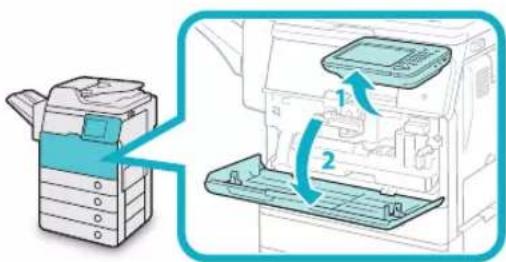
Open the front cover.02
text_image
Diagram showing printer operation with labeled parts and directional arrows indicating process flow- Lift the control panel.
- Open the front cover.
Remove the displayed toner cartridge.
03
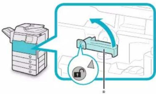
- Turn the toner cartridge lock lever counterclockwise so that the arrow marks on the lever and its axis face each other.
text_image
Diagram illustrating a printer's internal mechanism with lock and pad symbols, showing process flow and component placement.\*: Toner Cartridge Lock Lever
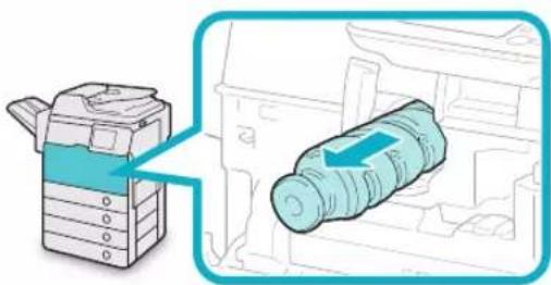
- Pull the toner cartridge out of the toner supply port.
natural_image
Illustration of a printer with a magnified view showing internal components (no text or symbols)Pull the toner cartridge out halfway with one hand, support it with the other hand from underneath, and then remove it completely while keeping it level.

WARNING
Do not burn or throw used toner cartridge into open flames, as this may cause the toner remaining inside the cartridges to ignite resulting in burns or a fire.

IMPORTANT
If the toner cartridge cannot be pulled out, check that the lever is turned all the way to the appropriate position.
Prepare the new toner cartridge.04
- Open a package of toner cartridge, and then remove the toner cartridge.
natural_image
Diagram of a mechanical component with a rotating shaft and housing, showing a blue arrow indicating direction (no text or symbols)- Remove the protective cap from the new toner cartridge.
natural_image
Diagram of a mechanical component with a rotating shaft and curved arrow indicating rotation (no text or symbols)Twist the protective cap of the new toner cartridge in the direction of the arrow to remove it.

IMPORTANT
Use only toner cartridges intended for use with the machine. (See "Consumables," on p. 57.) Do not touch the opening of the toner cartridge or subject it to shock by hitting it. Doing so may cause the toner to leak out of the cartridge.

natural_image
Illustration of a hand holding a connector with a no-smoking symbol (no text or labels present)Insert the new toner cartridge in the 05 toner supply port as far as it will go.
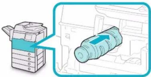
natural_image
Illustration of a printer with a magnified view showing internal components (no text or symbols)
NOTE
Support the new toner cartridge with your hand from underneath while pushing it into the machine with your other hand.

Turn the toner cartridge lock lever clockwise so that the arrow marks on the lever and its axis face each other.
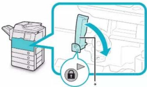
text_image
Diagram illustrating a printer's internal mechanism with lock and padlock operation, showing a printer's open position and lock state.*: Toner Cartridge Lock Lever
Close the front cover.07
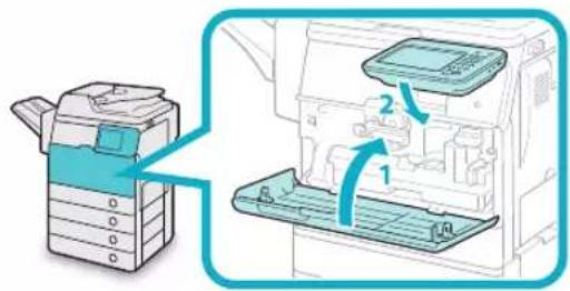
text_image
Diagram showing a printer with labeled parts and directional arrows indicating assembly or operation.- Close the front cover of the main unit.
- Lower the control panel back in place.

CAUTION
When closing the covers, be careful not to get your fingers caught, as this may result in personal injury.
Replacing the Waste Toner Container
When the waste toner container nears capacity, a message appears on the touch panel display. In this case, you should prepare a new waste toner container.
When the waste toner container is full, a screen with instructions on how to replace the waste toner container appears on the touch panel display. You can follow the procedure described below to replace the waste toner container.
Even if you do not replace the waste toner container immediately, you can perform printing for a while. The number of prints you can make depends on the content you print.
However, if you continue printing, an error will occur and you will become unable to print.

WARNING
Do not burn or throw used waste toner containers • into open flames. Also, do not store waste toner containers in places exposed to open flames, as this may cause the toner to ignite, resulting in burns or a fire.
If you accidentally spill or scatter toner, carefully gather the toner particles together or wipe them up with a soft, damp cloth in a way that prevents inhalation. Never use a vacuum cleaner that does not have safeguards against dust explosions to clean up spilled toner. Doing so may cause a malfunction in the vacuum cleaner, or result in a dust explosion due to static discharge.

CAUTION
If toner is ingested, consult a physician • immediately.
If toner gets onto your hands or clothing, wash it off immediately with cold water. Washing it off with warm water will set the toner, and make it impossible to remove the toner stains.

IMPORTANT
Your local authorized Canon dealer will dispose of used waste toner containers. Use the provided cover to cover up the opening of the used waste toner container.
Used toner cannot be reused. Do not mix new and used toner together.
Use only waste toner containers intended for use • with this machine.
Do not replace the waste toner container before • the message prompting you to replace it appears on the touch panel display.

NOTE
Complete instructions on how to replace the waste toner container can be accessed by pressing [Previous] or [Next] on the touch panel display.
Open the front cover.01
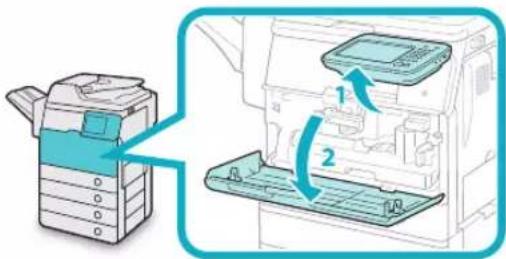
text_image
Diagram showing a printer with blue ribbon and two labeled parts, illustrating the process of inserting or removing a device.- Lift the control panel.
- Open the front cover.
02
Turn the toner container lock lever counterclockwise 90 degrees to unlock the waste toner container.
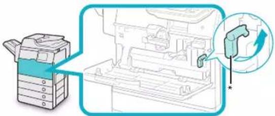
natural_image
Diagram showing a printer and mechanical device with a magnified view of a component (no text or symbols present)*: Toner Container Lock Lever
Remove the waste toner container.03
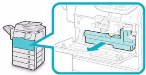
natural_image
Diagram showing a printer with a blue ribbon and internal components, no text or symbols present
CAUTION
When removing the waste toner container, be careful not to tilt it, as the toner may spill and get onto your hands or clothing.
Detach the cap mounted on the side of the container, and use it to seal the opening so that the waste toner does not spill out.
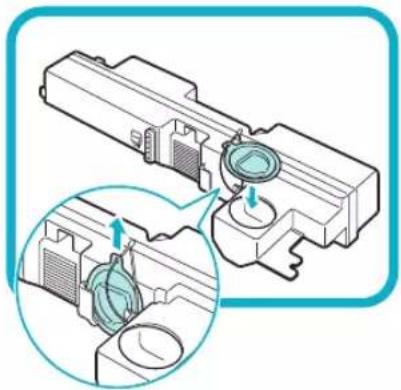
natural_image
Technical illustration of a mechanical assembly with two views of a component (no text or symbols)Put the removed waste toner container into a bag, and then tie it up at the top to prevent the toner remaining inside the cartridge from scattering.
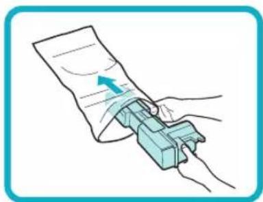
natural_image
Illustration of a hand using a mechanical device to press or attach a document (no text or symbols visible)
NOTE
Use a bag in the box in which the new waste toner container is stored.
Put the bag containing the used waste toner container into the box.
06
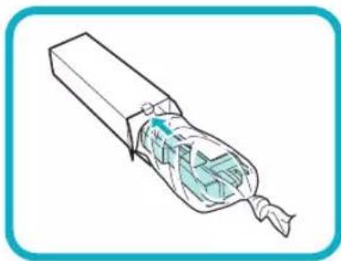
natural_image
Illustration of a cable or wire connector with internal insulation and twisted tip (no text or symbols)Insert the new container in place.07
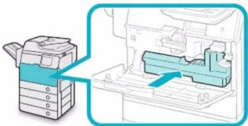
natural_image
Diagram showing a printer with internal components and a magnified view of the device (no text or symbols present)08 Turn the toner container lock lever clockwise 90 degrees to lock the container.
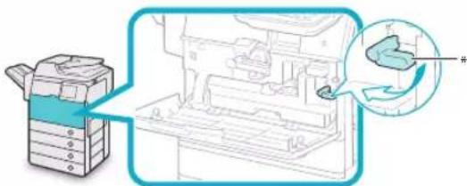
text_image
Diagram showing a printer with internal components and a magnified view of a device's internal structure, likely illustrating a printing or assembly process.*: Toner Container Lock Lever
Close the front cover.09
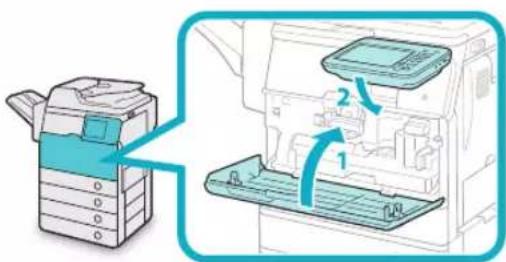
text_image
Diagram showing printer operation with labeled parts and directional arrows indicating process flow- Close the front cover of the main unit.
- Lower the control panel back in place.

CAUTION
When closing the covers, be careful not to get your fingers caught, as this may result in personal injury.
Replacing the Drum Unit
You can follow the procedure below to replace the drum unit.

IMPORTANT
When no drum unit is installed in the machine, the message

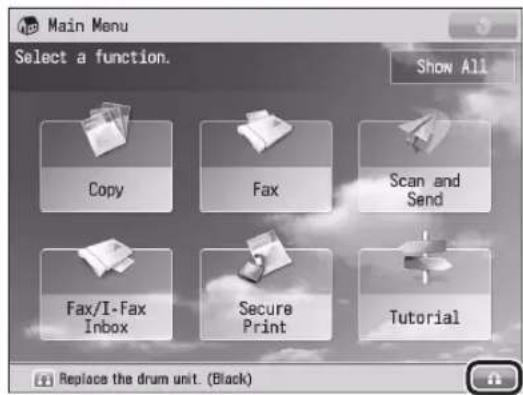
text_image
Main Menu Select a function. Show All Copy Fax Scan and Send Fax/I-Fax Inbox Secure Print Tutorial Replace the drum unit. (Black)The name of the part that needs to be replaced is displayed.
Open the front cover.02
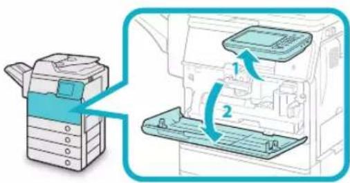
text_image
Diagram showing a printer with two labeled parts, indicating file transfer or assembly steps.- Lift the control panel.
- Open the front cover.
Open the right cover of the main unit.03 If the multi-purpose tray is opened, close it before opening the right cover.
- Pull the lever on the right cover of the main unit.

natural_image
Illustration of a printer next to an open digital machine, showing the printer's side panel and control panel (no text or symbols present)- Gently open the cover downward until it stops.
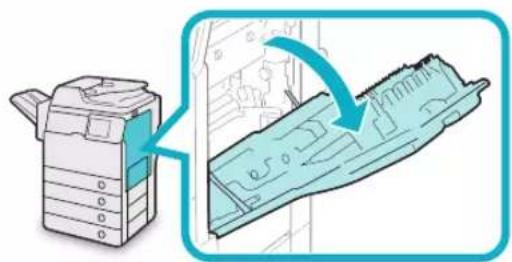
natural_image
Illustration of a printer with a magnified view showing internal structure (no text or symbols)
IMPORTANT
Always open the right cover as illustrated during installation to prevent damage to the drum unit.
04
Turn the toner container lock lever counterclockwise 90 degrees to unlock the waste toner container.
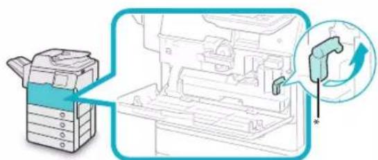
text_image
Diagram showing a printer with a magnified view of internal components, highlighting a component with an arrow and asterisk.*: Toner Container Lock Lever
Remove the waste toner container.05
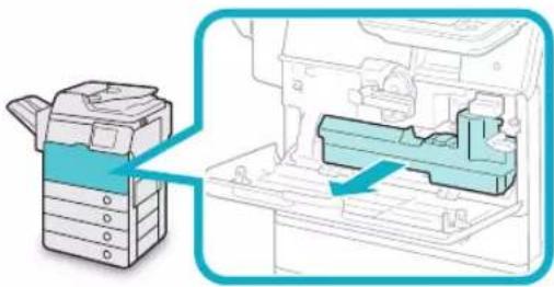
natural_image
Diagram showing a printer with a blue arrow pointing to a mechanical component inside a machine (no text or symbols present)
CAUTION
When removing the waste toner container, be careful not to tilt it, as the toner may spill and get onto your hands or clothing.
Detach the cap mounted on the side of the container, and use it to seal the opening so that the waste toner does not spill out.

natural_image
Technical illustration of a mechanical assembly with a magnified inset showing internal components (no text or symbols)Unlock the drum unit by turning the 07 drum unit lock lever counterclockwise until it stops.

text_image
Diagram showing a printer with a magnified view of the printer's internal structure, highlighting a component with a pencil and a dollar sign.*: Drum Unit Lock Lever
While lifting the lever under the tab, 08 slowly pull the drum unit until the blue marking appears.
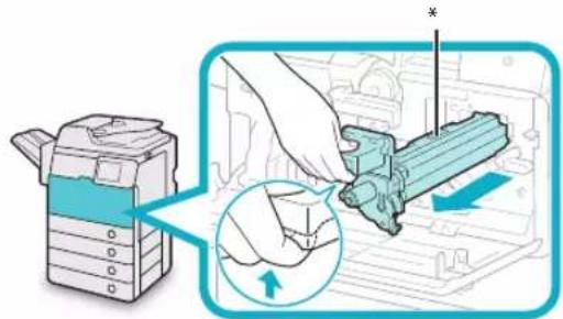
text_image
Diagram illustrating a printer's internal structure being inserted into a machine, with an inset showing the insertion process.*: Blue Marking
Holding the part with the blue 09 marking, pull the drum unit out slightly upward.
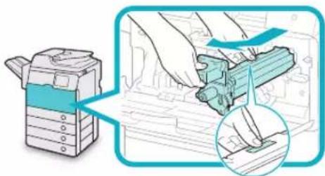
text_image
Diagram illustrating a printer's internal structure and tool path, showing hand positioning and magnified view of the component.Remove the drum unit from its 10 protective bag.
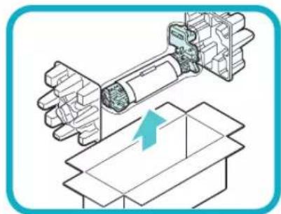
natural_image
Technical illustration of a robotic arm interacting with a box, showing mechanical components and a blue upward arrow (no text or symbols)
IMPORTANT
Do not touch or expose the cylindrical, blue-green part to light for a long time, as the print quality may deteriorate.
Do not expose the drum unit to direct sunlight or strong light.
Condensation (water droplets on the inside or outside) may form on the drum unit when it is brought into an environment with a sudden change in temperature or humidity. When moving a new drum unit to a location with change in temperature, leave the drum unit in the protective bag at the new location for two or more hours to allow it to adjust to the new temperature.
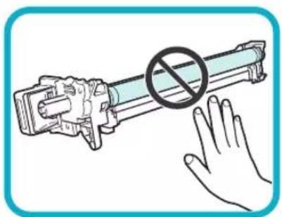
natural_image
Illustration of a hand holding a cylindrical device with a prohibition symbol (no text or labels)Pull the two orange rings out, and remove the protective cover.

natural_image
Diagram of a mechanical device with motion arrows indicating movement, no text or symbols presentHolding the tab and the part with the blue marking, slowly insert the drum unit until it stops.
When inserting the drum unit, make sure that the drum unit slides properly along the rails on the machine.
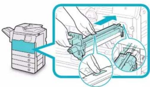
text_image
Diagram illustrating a printer's internal structure and mechanical assembly, with magnified views highlighting the components.Lock the drum unit by turning the 13 drum unit lock lever clockwise until it stops.
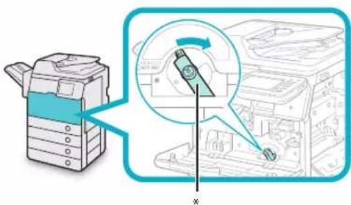
text_image
Diagram illustrating printer operation with magnified view of internal components and labeled parts*: Drum Unit Lock Lever
Remove the cap from the container 14 opening and attach it to the protrusion on the side of the container.
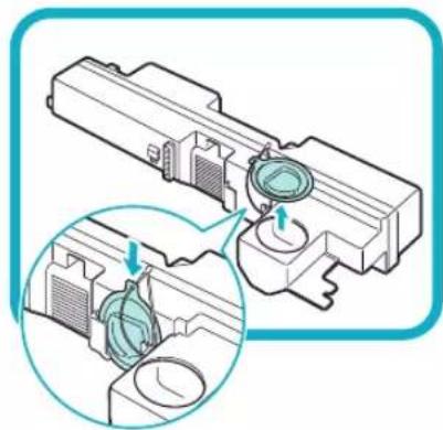
natural_image
Technical illustration of a mechanical assembly with a magnified inset showing internal components (no text or symbols)IMPORTANT
Be careful not to spill the waste toner when detaching the cap.
Insert the waste toner container. 15
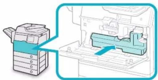
natural_image
Diagram showing a printer with a blue arrow pointing to a mechanical component inside a machine (no text or symbols present)16 Turn the toner container lock lever clockwise 90 degrees to lock the container.
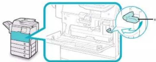
text_image
Diagram showing a printer with a magnified view of the internal structure, likely illustrating a printer's internal components or assembly.*: Toner Container Lock Lever
Place your hand where the hand symbol (is located on the right cover of the main unit, and then gently close the right cover until it clicks into place.
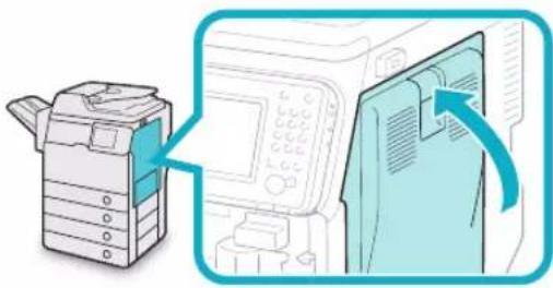
natural_image
Illustration of a printer with a close-up view showing the printer's internal structure (no text or symbols present)
CAUTION
When closing the cover, be careful not to get your fingers caught, as this may result in personal injury.
Close the front cover. 18
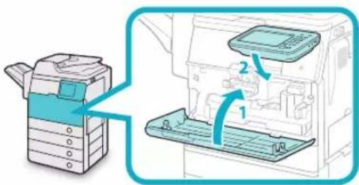
text_image
Diagram showing printer operation with labeled parts and directional arrows indicating process flow- Close the front cover of the main unit.
- Lower the control panel back in place.
A notification will inform you when the drum has been replaced.

CAUTION
When closing the covers, be careful not to get your fingers caught, as this may result in personal injury.
Press [Close]. 19
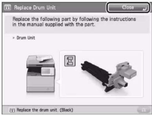
text_image
Replace Drum Unit Close Replace the following part by following the instructions in the manual supplied with the part. ► Drum Unit Replace the drum unit (Black)Press [Yes].20

text_image
Replace Drum Unit Close Replace the following part by following the instructions Is replacement of the following parts finished? ► Drum Unit Yes No Replace the drum unit. (Black)Press [Yes] to start initializing the drum unit.

NOTE
If you want to initialize the drum unit at a later time, or if you have not yet replaced the drum, press [No]. For instructions on initializing the drum unit, see e-Manual > Settings/Registration.
Routine Cleaning
If the original is not copied clearly, clean the following parts of the machine. For high-quality printouts, we recommend cleaning these parts once or twice a month.
Platen glass ●
Underside of the feeder ●
Feeder scanning area and rollers ●

WARNING
- When cleaning the machine, first turn OFF the main power switch, and disconnect the power cord. Failure to observe these steps may result in a fire or electrical shock.
- Disconnect the power cord from the power outlet regularly, and clean the area around the base of the power plug's metal pins and the power outlet with a dry cloth to ensure that all dust and grime is removed. If the power cord is connected for a long period of time in a damp, dusty, or smoky location, dust can build up around the power plug and become damp. This may cause a short circuit and result in a fire.

IMPORTANT
- When cleaning with a cloth, do not dampen it too much, as this may damage the original or break the machine.
- Do not use alcohol, benzene, paint thinner, or other solvents for cleaning. Doing so may result in damage to the plastic parts.
Cleaning the Platen Glass and Underside of the Feeder
If the platen glass or the underside of the feeder is dirty, the original may not be scanned clearly. Clean the platen glass and the underside of the feeder by following the procedure below.
Clean the platen glass and the 01 underside of the feeder with a cloth which is wrung after being dampened in water, and then wipe them clean with a soft, dry cloth.
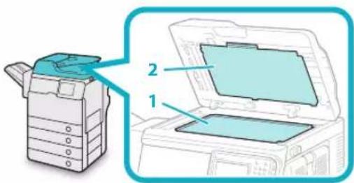
text_image
Diagram showing a printer with labeled parts, including a folder and open case, with numbered annotations.- Clean the platen glass.
- Clean the underside of the feeder.

NOTE
If stains won't come out, use detergent instead of water.
Manual Feeder Cleaning
If originals that have been fed through the feeder have streaks or appear dirty, clean the feeder's rollers.
It is recommended that you clean the rollers of the feeder with a cloth which is wrung after being dampened in water, and then wipe them clean with a soft, dry cloth.

IMPORTANT
Spin the rollers while cleaning them. If the document feed scanning area is dirty, documents may not be scanned clearly. Do not dampen the cloth too much, as excess water may damage the machine.

Gently open the feeder cover.
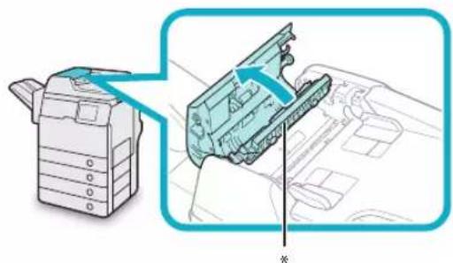
natural_image
Diagram showing a printer device and its internal component, with no visible text or symbols*: Feeder Cover
When the feeder cover is completely opened, the inner cover is also opened.
Clean the rollers (a total of eight 02 places) inside the feeder cover with a water-moistened cloth. Then, wipe the area with a soft, dry cloth.
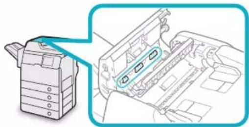
natural_image
Technical illustration of a printer holder and internal structure (no text or symbols)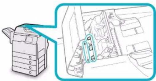
natural_image
Diagram showing a printer device and its internal components, no text or symbols presentClean the rollers (a total of four places) inside the inner cover with a water-moistened cloth. Then, wipe the area with a soft, dry cloth.
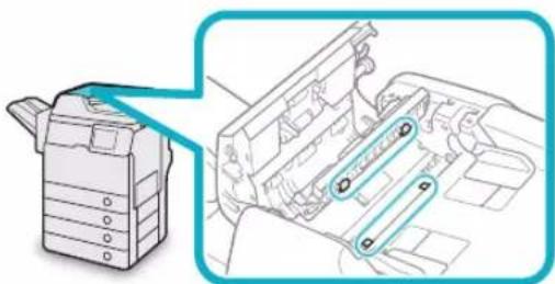
natural_image
Technical line drawing of a printer holder and internal components (no text or symbols)Spin the rollers with your hand while cleaning them.
Clean the transparent plastic parts of the inner cover and inside it (a total of three places) with a water-moistened cloth. Then, wipe the area with a soft, dry cloth.

natural_image
Technical illustration of a printer with a magnified inset showing internal components (no text or symbols)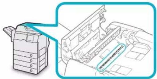
text_image
Technical diagram showing a printer with a highlighted internal component labeled 'PTC-10000000000000000000000000000000000000000000000000000000000000000000000000000000000000000000000000000' alongside a schematic diagram of the printer's internal structure.Lift the feeder.05
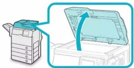
natural_image
Illustration of a printer with an open lid and a blue arrow indicating the process (no text or symbols present)06 Clean the feeder scanning area (the left side of the platen glass) and the white strip of plate under the feeder with a water-moistened cloth. Then, wipe the area with a soft, dry cloth.
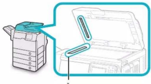
natural_image
Illustration of a printer with a magnified view showing internal components (no text or symbols)*: Feeder Scanning Area
Hold the feeder with one hand, and 07 then open the cover under the feeder with the other.
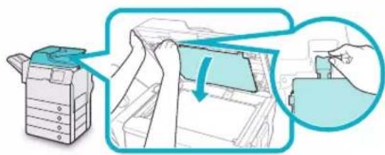
natural_image
Illustration of a printer being placed on top of a printer, showing the printer's handle and zoomed-in section (no text or symbols)Clean the rollers (a total of eight places) inside the cover under the feeder with a water-moistened cloth. Then, wipe the area with a soft, dry cloth.
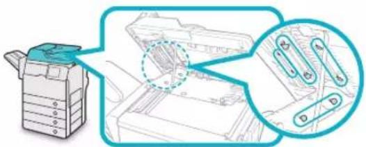
natural_image
Illustration of a printer with a magnified view showing internal components (no text or symbols)Spin the rollers with your hand while cleaning them.
Close the cover under the feeder.09
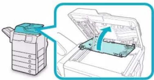
natural_image
Illustration of a printer with a blue arrow indicating the open lid, showing internal structure (no text or symbols)
CAUTION
When closing the cover, be careful not to get your fingers caught, as this may result in personal injury.
Gently lower the feeder. 10
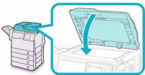
natural_image
Illustration of a printer with a lid removed from its side, showing the open lid and printer casing (no text or symbols present)
CAUTION
When lowering the feeder, be careful not to get your fingers caught, as this may result in personal injury.
Gently close the feeder cover. 11
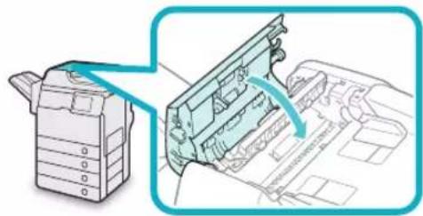
natural_image
Diagram showing a printer device and its internal structure with arrows indicating assembly (no text or symbols present)
CAUTION
When closing the cover, be careful not to get your fingers caught, as this may result in personal injury.
Consumables
The following consumables are available from Canon. For more information, contact your local authorized Canon dealer. We recommend that you order paper stock and toner from your local authorized Canon dealer before your stock runs out.
Recommended Paper ●
In addition to plain paper (A4 and A5 size), recycled paper, colour paper, transparencies (recommended for this machine), labels, and other types of paper stock are available.

CAUTION
Do not store paper in places exposed to open flames, as this may cause the paper to ignite, resulting in burns or a fire.

IMPORTANT
Some commercially available paper types are not suited for this machine. Contact your local authorized Canon dealer when you need to purchase paper.
To prevent moisture build-up, tightly wrap any • remaining paper in its original package for storage.

NOTE
For high-quality printouts, use paper recommended by Canon.
Toner ●
If a message prompting you to replace the toner cartridge appears on the touch panel display, replace the used toner cartridge with a new one. Use only toner cartridges intended for use with this machine.
For optimum print quality, using Canon genuine toner is recommended.
| Product Name | Supported Canon Genuine Toner |
| imageRUNNER ADVANCE 500i/400i | Canon C-EXV 43 Black Toner |
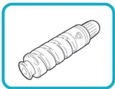
natural_image
Line drawing of a cylindrical mechanical component with internal grooves and a triangular feature (no text or symbols)
WARNING
Do not burn or throw used toner cartridges into open flames, as this may cause the toner remaining inside the cartridges to ignite, resulting in burns or a fire.
Do not store toner cartridges in places exposed to open flames, as this may cause the toner to ignite, resulting in burns or a fire.
If you accidentally spill or scatter toner, carefully gather the toner particles together or wipe them up with a soft, damp cloth in a way that prevents inhalation. Never use a vacuum cleaner that does not have safeguards against dust explosions to clean up spilled toner. Doing so may cause a malfunction in the vacuum cleaner, or result in a dust explosion due to static discharge.

CAUTION
Keep toner out of the reach of small children. If toner is ingested, consult a physician immediately.

IMPORTANT
Store toner cartridges in a cool location, away from direct sunlight. (The recommended storage conditions are temperatures below 30°C and humidity below 80%.)
Do not store toner cartridges in an upright position.
[Be careful of counterfeit toners] •
Please be aware that there are counterfeit Canon toners in the marketplace. Use of counterfeit toner may result in poor print quality or machine performance. Canon is not responsible for any malfunction, accident or damage caused by the use of counterfeit toner.
For more information, see http://www.canon.com/counterfeit.
Drum Unit ●
When you replace the drum unit with a new one, be sure to use only drum units intended for use with the machine.
| Product Name | Supported Canon Genuine Drum Unit |
| imageRUNNER ADVANCE 500i/400i | Canon C-EXV 37 Drum Unit |
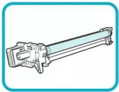
natural_image
Technical line drawing of a mechanical component with no visible text or symbolsStaple Cartridge ●
| Finisher | Staple Cartridge (Name/Shape) |
| Staple Finisher-R1 | Canon Staple-P1 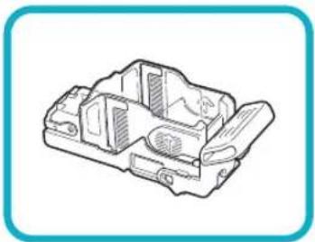 |
Genuine Consumables ●
Canon continuously develops technology innovations in Canon Toners, Drums and Cartridges, specifically designed for use in Canon Multi-Functional machines. Experience the benefits of optimal print performance, print volume and high quality outputs, achieved through Canon's new advanced technologies. Therefore, the use of Canon genuine consumables is recommended for your Canon Multi-Functional machines.
Go to http://www.canon-europe.com/consumables/ to understand the secret behind Canon's Consumable products.

text_image
CANON GENUINE TONER, DRUM & CARTRIDGEWhen an Error Message/Error Code Is Displayed
When an Error Message Is Displayed
Error messages may appear on the touch panel display of the machine or the Web browser.
Self-diagnostic error messages appear in the following cases:
When scanning or printing cannot be performed because of an operational error
When you need to make a decision or take some ● action during scanning or printing
When you need to make a decision or take some ● action while browsing the network
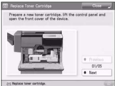
text_image
Replace Toner Cartridge Prepare a new toner cartridge, lift the control panel and open the front cover of the device. Previous 01/05 Next Replace toner cartridge.Example of an Error Message on the Touch Panel Display

text_image
Portal Application Course To install the software application, a license is required or installed at the service line. Identify a server file.Example of an Error Message on the Web Browser
For information on error messages and instructions on resolving errors, see e-Manual > Problem Solving.
When an Error Code Is Displayed
If a job or operation does not complete successfully, the error code is displayed on the Details screen for Log on the Status Monitor/Cancel screen.
You can check the error code in the following locations:
Details screen for Log on the Status Monitor/ Cancel screen:
When a job or operation is not completed normally:
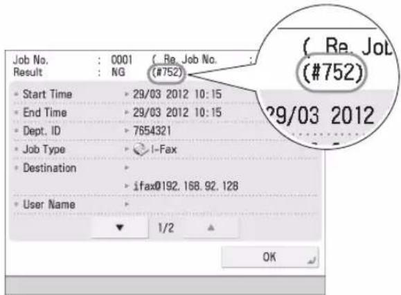
text_image
Job No. : 0001 (Re. Job No. : Result : NG (#752) Start Time 29/03 2012 10:15 End Time 29/03 2012 10:15 Dept. ID 7654321 Job Type I-Fax Destination ifax@192.168.92.128 User Name 1/2 OK ( Re. Job (#752) 29/03 2012Results row of the Communication Management ● Report:
If an error occurs during a send, receive, or fax job, the error code is printed.
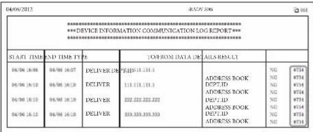
text_image
04/08/2012 04/08/2012 04/08/2012 04/08/2012 04/08/2012 04/08/2012 04/08/2012 04/08/2012 04/08/2012 04/08/2012 DELIVER DEPT. ID 111.111.111.1 DELIVER 111.111.111.1 DELIVER 222.222.222.222 DELIVER 333.333.333.333 ADDRESS BOOK DEPT.ID ADDRESS BOOK DEPT.LID ADDRESS BOOK DEPT.ID ADDRESS BOOK ADDRESS BOOK NG #75# NG #75# NG #75# NG #75# NG #75# NG #75# NG #75# NG #75# NG #75# NG #75# NG #75# NG #75# NG #75# NG #75# NG #75# NG #75# NG #75# NG #69# NG #69# NG #69# NG #69# NG #69# NG #69# NG #69# NG #69# NG #69# NG #69# NG #69# NG #69# NG #69# NG #69# NG #69# NG #69# NG #69# NG @75# NG @75# NG @75# NG @75# NG @75# NG @75# NG @75# NG @75# NG @75# NG @75# NG @75# NG @75# NG @75# NG @75# NG @75# NG @75# NG @75# NG #75# NG #75# NG #75# NG #75# NG #75# NG #75# NG #75# NG @75# NG @75# NG @75# NG @75# NG @75# NG @75# NG @75#For information on error codes and instructions on resolving errors, see e-Manual > Problem Solving.
Service Call Message
If a malfunction occurs and the machine cannot operate normally, a screen prompting you to contact your local authorized Canon dealer is displayed.

text_image
Turn the main power switch OFF & ON. • If the device still does not operate normally, contact your service representative with the error code below. E000000-0000If a screen such as the one above is displayed, contact your local authorized Canon dealer. (See "Contacting Your Local Authorized Canon Dealer," on p. 60.)
When [Limited Func. Mode] is displayed: ●
![CANON imageRUNNER ADVANCE 400i - When [Limited Func. Mode] is displayed: ● - 1](/content/2026/04/666717/images/d08c76a75eab545eb50dcd494b3ae8db736e14d09cc39d20bb87307d39d8eaea.jpg)
text_image
Turn the main power switch OFF and ON. • If the device still does not operate normally, contact your service representative with the error code below. E000540-8001 The finisher output tray cannot move up or down. Make sure that objects are not placed in the range of tray movement. • Press [Limited Func. Mode] to continue operation when using limited functions if the device is not functioning correctly even after the main power switch (on left side of main unit) was turned OFF, then ON again. Limited Func. ModeIf [Limited Func. Mode] is displayed, you can temporally set the Limited Functions Mode to continue to use the machine until the cause of the malfunction is cleared. (See "Setting the Limited Functions Mode from the Service Call Message Screen," on p. 61.)
If a screen such as the one below is displayed and the print or scan function does not operate normally, some functions may still be available.
When the print or scan function does not operate normally:
The selected function cannot be used. Press [Main Menu] to return to the Main Menu
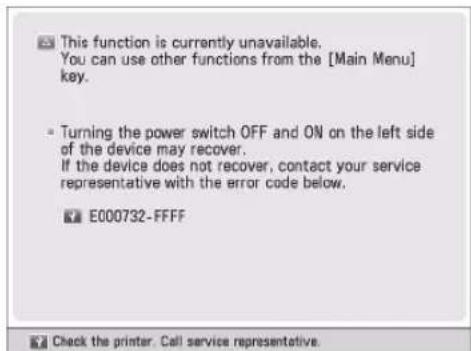
text_image
This function is currently unavailable. You can use other functions from the [Main Menu] key. Turning the power switch OFF and ON on the left side of the device may recover. If the device does not recover, contact your service representative with the error code below. E000732-FFFF Check the printer. Call service representative.When a service call message is displayed on the bottom of the screen:
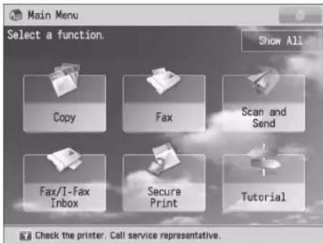
text_image
Main Menu Select a function. Show All Copy Fax Scan and Send Fax/I-Fax Inbox Secure Print Tutorial Check the printer. Call service representative.Even if a message prompting you to call your service representative appears on the bottom of the screen, some functions may still be available.
For more information on the available functions, see "Functions Available When the Printer/Scanner Cannot Be Used Due to an Error," on p. 61.
Contacting Your Local Authorized Canon Dealer
If a screen prompting you to contact your local authorized Canon dealer is displayed, follow the procedure described below.
Turn the main power OFF and then ON.
IMPORTANT
For instructions on turning ON and OFF the main power of the machine, see "Main Power and Energy Saver Key," on p. 24.
If the operation still cannot be 02 performed correctly, turn the main power switch OFF, remove the power plug from the outlet, and contact your local authorized Canon dealer.
WARNING
Mishandling the power plug is dangerous. For instructions on handling the power plug, see "Important Safety Instructions," on p. 79.

NOTE
When you contact your local authorized Canon dealer, have the following information available:
Product name•
Details of the malfunction•
The error code displayed on the touch panel display.
Setting the Limited Functions Mode from the Service Call Message Screen
When [Limited Func. Mode] is displayed, follow the procedures below.

IMPORTANT
If you turn OFF the main power switch when there is a job waiting to print, that job is erased.

NOTE
If you set Limited Functions Mode to 'On' from the Service Call Message screen, [Limited Functions Mode] in [Management Settings] (Settings/Registration) is also set to 'On'. (See e-Manual > Security.)

Press [Limited Func. Mode] → [Yes].
A message prompting you to restart the machine (turning the main power switch OFF, and then ON) appears.
Turn the main power OFF and then ON.

IMPORTANT
For instructions on turning ON and OFF the main power of the machine, see "Main Power and Energy Saver Key," on p. 24.
Functions Available When the Printer/Scanner Cannot Be Used Due to an Error
You can use the following functions even when the Print and Scan functions are restricted.
Main Menu Screen ●
√ : Available -: Unavailable
| Available Functions | When the Print function is restricted | When the Scan function is restricted |
| Copy -- | ||
| Fax | ^*1 | - |
| Scan and Send - | √ | |
| Scan and Store - | √ | |
| Access Stored Files | - | ^*2 |
| Fax/I-Fax Inbox | - | √ |
| Secure Print | - | √ |
| Remote Scan | √ | - |
| Web Access | √ | √ |
| Shortcut to Settings/Registration | - | - |
| Tutorial | √ | √ |
| iW Function Flow | - | - |
| Other MEAP Applications*3 | √ | √ |
Touch Panel Display Left Side
: Available -: Unavailable
| Available Functions | When the Print function is restricted | When the Scan function is restricted |
| Quick Menu *4 | √ | - |
| The Status Monitor/Cancel Screen | √*5 | - |
Control Panel ●
√ : Available -: Unavailable
| Available Functions | When the Print function is restricted | When the Scan function is restricted |
| Settings/Registration | - | - |
Operation From a Computer ●
√ : Available -: Unavailable
| Available Functions | When the Print function is restricted | When the Scan function is restricted |
| Remote UI | √ | √ |
| MEAP Application*3 | √ | √ |
*1 Sending a fax from a computer is not available.
*2 [Add Files (Scan and Store)] on the Edit File screen is not available.
*3 Available by installing each MEAP application. May not be available depending on the restricted functions.
*4 The registered button may not be available depending on the restricted functions.
*5 [Print List] on the Job Log screen and [Register] on the Consumable screen are not available.

IMPORTANT
A print job is automatically cancelled when the • Print function is restricted. A scan job is automatically cancelled when the Scan function is restricted.
The machine may not enter the Sleep mode • completely when a function is restricted due to an error.

NOTE
If the target function is restricted due to an error, the function is not available when you use the shortcut key on the left side of the touch panel display or when you use the Quick Menu.
Locations of Staple/Paper Jams
Paper and staple jams may occur in the following parts of the machine. By following the instructions in the applicable section, you can clear staple/paper jams. For details on these procedures, see the e-Manual.
Paper Jams: e-Manual Solving > Locations of Paper Jams
Staple Jams: e-Manual Solving > Clearing Staple Jams (For Staple Finisher-R1)
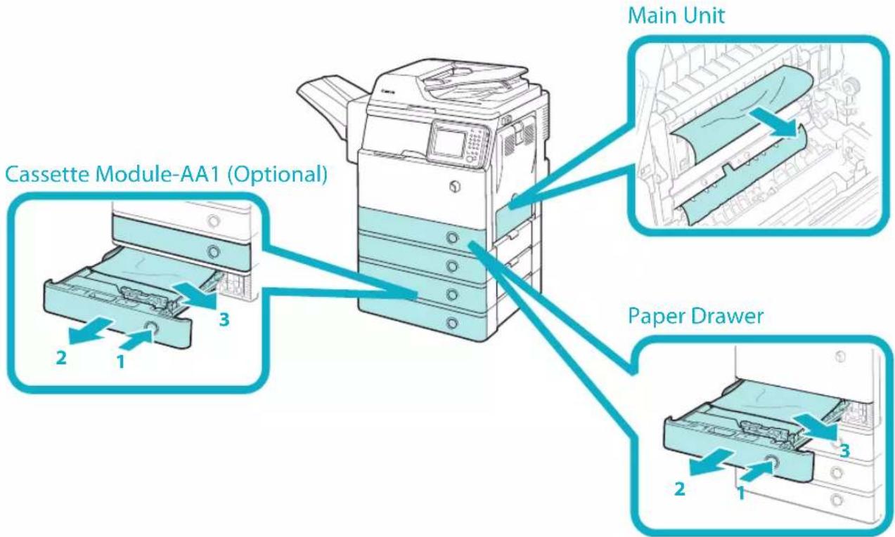
text_image
Main Unit Cassette Module-AA1 (Optional) Paper Drawer 2 1 3 2 1 3Staple Finisher-R1 (Optional)
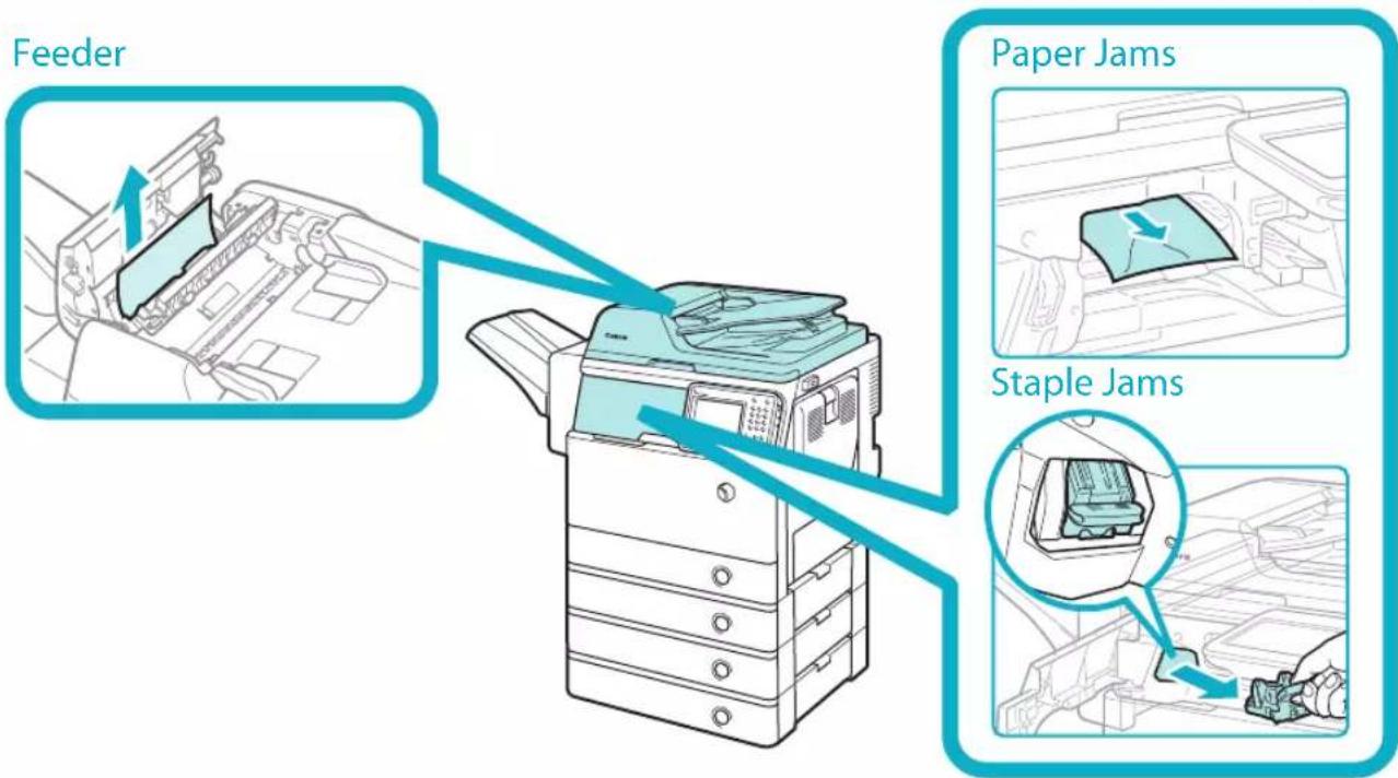
text_image
Feeder Paper Jams Staple JamsSpecifications
5
Specifications 66
Main Unit 66
Feeder 68
Cassette Module-AA1 68
Envelope Cassette-E1....68
Staple Finisher-R1....69
Copy Card Reader-F1 69
Super G3 FAX Board-AM1 70
Send Function 71
Network Environment....73
Printer Settings 73
Specifications
Specifications are subject to change without notice for product improvement or future release.
Main Unit
| Item Specifications | |
| Name Canon imageRUNNER ADVANCE 500i/400i | |
| Type Reader-printer combined, Console | |
| Resolution for Reading 600 x 600 dpi (Black-and-White)300 x 300 dpi (Full Colour) | |
| Resolution for Writing 600 x 600 dpi (Copy)1,200 x 1,200 dpi (Print) | |
| Number of Tones 256 | |
| Available Paper Paper Drawer: | Weight:64 to 105 g/m2Type:Plain 1 (64 to 80 g/m2), Plain 2 (81 to 90 g/m2), Recycled, Colour, Pre-Punched, and Heavy 1 (91 to 105 g/m2)Multi-Purpose Tray:Weight:64 to 128 g/m2Type:Plain 1 (64 to 80 g/m2), Plain 2 (81 to 90 g/m2), Recycled, Colour, Pre-Punched, Bond, Heavy 1 (91 to 105 g/m2), Heavy 2 (106 to 128 g/m2), Labels, Transparency, and Envelopes |
| Acceptable Originals Sheet, book, and three dimensional objects (up to 2 kg) | |
| Paper Sizes Paper Drawer: | A4, A5, and Custom size (139.7 mm x 210 mm to 216 mm x 355.6 mm)Multi-Purpose Tray:A4, A5, Custom size (99 mm x 139.7 mm to 216 mm x 355.6 mm), and Envelopes |
| Warm-Up Time* After Powering ON (when [Quick Startup Settings for Main Power] is set to 'Off'): 34 seconds or lessAfter Powering ON (when [Quick Startup Settings for Main Power] is set to 'On'): 10 seconds or lessThe time until key operations can be performed on the touch panel display is 7 seconds or less.Even if [Quick Startup Settings for Main Power] is set to 'On', the machine does not startup quickly, depending on the situations.Returning from the Sleep mode: 10 seconds or less*Activation time may vary, depending on the environment and conditions under which the machine is being used. (At a room temperature of 20 °C in all above cases.) | |
| First Copy Time 5 seconds or less | |
| Copy Speed* 1:1 (sheet/minute) | imageRUNNER imageRUNNER ADVANCE 500i ADVANCE 400iA4 50 40A5 25 25* Except when paper is fed from the multi-purpose tray.The copy speed may vary, depending on the settings for paper type, paper size, and the sending method. When continuously copying, adjustments for machine temperature or image quality may cause machine operations to pause or become slow. |
| Margin Top: 5.0 mm or less | Left and Right: 5.0 mm or lessBottom: 5.0 mm or less |
| Magnification Regular paper size: | Same Ratio1:1Reduction1:0.70 (A4 → A5)1:0.501:0.25Enlargement1:1.41 (A5 → A4)1:2.001:4.00Copy Ratio: 25 to 400% (in 1% increment) |
| Paper Feeding System/Capacity Paper | Drawer:550 sheets (80 g/m2)Multi-Purpose Tray:100 sheets (80 g/m2) |
| Multiple Copies 1 to 999 sheets | |
| Memory Capacity 1.5 GB | |
| Hard Disk Capacity* 160 GB (Used space: 80 GB)* The hard disk capacity is subject to change in future release. | |
| Power Source 220 - 240 V AC, 50/60 Hz, 5.0 A | |
| Power Consumption Maximum Power Consumption:1.6 kWWhen the machine is in the Sleep mode*:1 WWhen the main power switch is turned OFF:0.5 W* Depending on the system and conditions of use, these values may differ. | |
| Dimensions (H x W x D) 633 mm x 560 mm x 567 mm | |
| Weight Approximately 47.9 kg | |
| Installation Space (W x D) | 787 mm x 567 mm(when the multi-purpose tray is extended) |
Feeder
| Item Specifications | |
| Original Feeding Mechanism Automatic Document Feeder | |
| Size and Weight of Originals Size: | A4 and A5Weight:Black and White Originals:1-sided scanning: 42 to 128 g/m^2 2-sided scanning: 50 to 128 g/m^2 Colour Originals:64 to 128 g/m^2 |
| Original Tray Capacity 100 sheets (80 g/ m^2 ) | |
| Original Scanning Speed Copying: | 1-sided scanning:50 sheets/minute (A4 in Black-and-White at 600 dpi)Scanning:1-sided scanning:50 sheets/minute (A4 in Black-and-White at 600 dpi/Colour at 300 dpi)25 sheets/minute (A4 in Colour at 600 x 300 dpi) |
Cassette Module-AA1
| Item Specifications | |
| Paper Sizes A4, A5, and Custom size (139.7 mm x 210 mm to 216 mm x 355.6 mm) | |
| Paper Drawers Capacity 550 sheets (80 g/m ^2 ) | |
| Power Source/Maximum Power Consumption | From the main unit/Approximately 20 W |
| Dimensions (H x W x D) 119 mm x 540 mm x 500 mm | |
| Weight Approximately 7.7 kg | |
| Item Specifications | |
| Acceptable Envelopes COM10 No.10, Monarch, DL, and ISO-C5 | |
| Capacity 50 sheets | |
| Feeding Speed 12 cpm | |
| Dimensions (H x W x D) 96 mm x 540 mm x 480 mm | |
| Weight Approximately 2.5 kg | |
Staple Finisher-R1
| Item Specifications | |
| Paper Size/Weight/Type Size: | A4, A5, Custom size (99 mm x 139.7 mm to 216 mm x 355.6 mm), and EnvelopesWeight:64 to 128 g/m2Type:Plain 1 (64 to 80 g/m2), Plain 2 (81 to 90 g/m2), Recycled, Colour, Pre-Punched, Bond, Heavy 1 (91 to 105 g/m2), Heavy 2 (106 to 128 g/m2), Labels, Transparency, and Envelopes |
| Capacity Per Tray No finishing set, Collate, Group mode:500 sheets (or 73.5 mm in height)Collate + Offset, Group + Offset mode:500 sheets (or 73.5 mm in height)Staple mode:20 sets (or 73.5 mm in height) | |
| Max. Stapling Capacity Corner Staple mode:64 to 90 g/m2: 50 sheets91 to 105 g/m2: 50 sheets106 to 128 g/m2: 30 sheets | |
| Power Source/Maximum Power Consumption | From the main unit/Approximately 50 W |
| Dimensions (H x W x D) 263 mm x 798 mm x 395 mm | |
| Weight Approximately 10.5 kg | |
| Installation Space Including the Main Unit (W x D) | 1,182 mm x 567 mm (when the multi-purpose tray is extended) |
Copy Card Reader-F1
| Item Specifications | |
| Available Cards Magnetic | |
| Card Readout Method Magnetic readout | |
| Magnetic Card Reading Direction Face up | |
| Store/Replay Replay | |
| Power Source From the main unit | |
| Dimensions (H x W x D) 40 mm x 88 mm | mm x 96 mm(excluding the attachment kit and cable) |
| Weight Approximately 200 g | (including the attachment kit and cable) |
Super G3 FAX Board-AM1

NOTE
Specifications remain the same even when the Super G3 2nd Line Fax Board is installed.
| Item Specifications | |
| Telephone Line Used*1 | Public Switched Telephone Network |
| Scan Line Density (Scan, Transmission) | Normal: 8 pels *2/mm x 3.85 line/mmFine: 8 pels *2/mm x 7.7 line/mmSuper-Fine: 8 pels *2/mm x 15.4 line/mmUltra-Fine: 16 pels *2/mm x 15.4 line/mm |
| Transmission Speed Super G3: 33.6 kbps, G3: 14.4 kbps | |
| Compression Method MH, MR, MMR, JBIG | |
| Transmission Type Super G3, G3 | |
| Sending Original Sizes A4, A5 | *3 |
| Receiving Paper Sizes A3, A4, and A5 | |
| Transmission Times JBIG: Approximately 2.6 seconds | |
| Auto Dial Function Address Book: 1,800 destinations(including destinations stored in one-touch buttons) | |
| Image Memory | Approximately 6,000 pages |
*1 When using an IP telephone service, facsimile communication may not be performed normally via an IP telephone line. It is recommended to use facsimile communication via a general telephone (Public Switched Telephone Network) line.
*2 Pels stands for picture elements (pixels).
*3 Sent as A4
Send Function
Scan Features ●
| Item Specifications | ||
| Communication Protocol FTP (TCP/IP), SMB (TCP/IP), WebDAV | ||
| Data Format TIFF, JPEG, PDF, XPS, OOXML (PowerPoint) | ||
| Resolution Black-and-White: | 100 x 100 dpi, 150 x 150 dpi, 200 x 100 dpi, 200 x 200 dpi, 200 x 400 dpi, 300 x 300 dpi, 400 x 400 dpi, 600 x 600 dpiColour:100 x 100 dpi, 150 x 150 dpi, 200 x 100 dpi, 200 x 200 dpi, 300 x 300 dpi | |
| System Environment Windows XP Professional SP3, Windows Server 2003 R2 SP2, Windows Vista SP2, Windows Server 2008 SP2, Windows Server 2008 R2 SP2, Windows 7, Windows 8, Windows Server 2012, Solaris 10, Mac OS X 10.4.x/10.5.x/10.6.x/10.7.x/10.8.x, Red Hat Linux 9 | ||
| Interface 1000BASE-T, 100BASE-TX, 10BASE-T | ||
| Colour Mode Automatic-Colour Select (Full Colour/Grayscale), Automatic-Colour Select(Full Colour/Black-and-White), Full Colour, Grayscale, Black-and-White | ||
| Original Type Text, Text/Photo, Photo | ||
| Other Preview, Browse Windows (SMB) File Server | ||
| Optional PDF/XPS/OOXML Functions | PDF Compact, Trace and Smooth, Encryption, OCR, Device Signature, User Signature, Optimization for Web*, PDF/A-1b, Reader Extensions | |
| XPS | Compact, OCR, Device Signature, User Signature | |
| OOXML | PowerPoint, OCR | |
* PDF files optimized for Web viewing.
E-Mail and I-Fax Features ●
| Item Specifications | ||
| Communication Protocol SMTP, POP3 | ||
| I-Fax Communication Mode Simple, Full | ||
| Resolution For Sending E-mail | (Black-and-White) | 100 x 100 dpi, 150 x 150 dpi, 200 x 100 dpi, 200 x 200 dpi, 200 x 400 dpi, 300 x 300 dpi, 400 x 400 dpi, 600 x 600 dpi |
| For Sending E-mail (Colour) | 100 x 100 dpi, 150 x 150 dpi, 200 x 100 dpi, 200 x 200 dpi, 300 x 300 dpi | |
| For Sending I-Fax (Black-and-White) | 200 x 100 dpi, 200 x 200 dpi, 200 x 400 dpi*, 300 x 300 dpi*, 400 x 400 dpi*, 600 x 600 dpi* | |
| Format E-mail TIFF, JPEG, PDF, XPS, O | OXML (PowerPoint) | |
| I-Fax (Black-and-White) | TIFF (MH, MR*, MMR*) | |
| Original Size E-mail A4, A5 | ||
| I-Fax A4, A5 | *2 | |
| Server Software Microsoft Exchange 2003 SP2, Microsoft Exchange 2007 SP2, Sendmail 8.14.4, Lotus Domino R7.0 | ||
| Other Searches a destination via the L | DAP Server, Preview | |
| Optional PDF/XPS/OOXML Functions (E-mail only) | Compact, Trace and Smooth, Encryption, OCR, Device Signature, User Signature, Optimization for Web*, PDF/A-1b, Reader Extensions | |
| XPS | Compact, OCR, Device Signature, User Signature | |
| OOXML | PowerPoint, OCR | |
*1 Available after setting RX conditions of the destination.
*2 Sent as A4.
*3 PDF files optimized for Web viewing.
Network Environment
Hardware Specifications ●
| Network Interface 10Base-T/100Base-TX/1000Base-T (RJ-45) |
Software Specifications ●
| Protocol Supported | |
| TCP/IP Frame type: Ethernet IIPrint applications: LPD/Raw/IPP/IPPS/FTP/WSD | |
| IPX/SPX Frame type: Ethernet II/Ethernet 802.2/Ethernet 802.3/Ethernet SNAP/Auto DetectPrint applications: Bindery PServer/NDS PServer/RPrinter/NPrinter |
Printer Settings
Software Specifications ●
| Command Language | PCL5e, PCL6, PostScript 3 |
| Resident Fonts PCL: 93 | Scalable fonts, 2 OCR fonts, 10 Bitmap fonts, and AndaleFont*(Japanese, Korean, Simplified Chinese, Traditional Chinese)PS: 136 Scalable fonts |
| Printable Area | PCL5e, PCL6: Reduced to 4.23 mm from the top, bottom, left, and right edges of the paper.PostScript 3: Reduced to 2.5 mm from the top, bottom, left, and right edges of the paper.When printing in the 0 mm mode, the upper margin becomes 2.5 mm, the lower margin becomes 2.5 mm, and the side margins both become 2.5 mm. The printable area is enlarged. |
* The optional PCL International Font Set needs to be activated to use Andale® and WorldType® Collection, or Andale Mono WT.
Product Name
Safety regulations require the product's name to be registered. In some regions where this product is sold, the following name(s) in parenthesis may be registered instead.
EMC requirements of EC Directive
This equipment conforms with the essential EMC requirements of EC Directive. We declare that this product conforms with the EMC requirements of EC Directive at nominal mains input 230 V, 50 Hz although the rated input of the product is 220 to 240 V, 50/60 Hz. Use of shielded cable is necessary to comply with the technical EMC requirements of EC Directive.
Laser Safety
This Product is certified as a Class 1 laser product under IEC60825-1:2007 and EN60825-1:2007. This means that the product does not produce hazardous laser radiation.
Since radiation emitted inside the product is completely confined within protective housings and external covers, the laser beam cannot escape from the machine during any phase of user operation.
Do not remove protective housings or external covers, except as directed by the equipment's manual.
Additional Information
When servicing or adjusting the optical system of the product, be careful not to place screwdrivers or other shiny objects in the path of the laser beam. Also, accessories such as watches and rings should be removed before working on the product.
The reflected beam, even though visible or invisible, can permanently damage your eyes.
The label shown below is attached to the paper drawer's right cover and toner supply port cover.
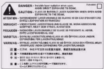
text_image
DANGER - Inade laser radiation when open. AVOID DIRECT EXPOTURE TO BEAM. CAUTION - INADE LANESE INDELE AVOID OUT EXPOTURE TO BEAM. OPEN AVOID EXPOTURE TO THE BEAM. ATTENTION - RADIATIONING LASER INVISIBLE DE CLASSE 35 EN CAB D'OUVERTURE EVITEZ L'EXPLOSION AU PARCELAN! VORSIGHT - VOLTING LABER STRAULING KLASSE 35 IN. MINN ABDECKUNG CROCCIÓN - CIRCUITABLE WITH SEM STRAULING FORESTEN PRECAUTION - RADIACION LASER INVISIBLE DE CLASE 35 PRESENTE AL ABRIEL. EVITE LA EXPLOSION KALAL NA VARCITUS - OYOUNG LABER STRAULING KLASSE 35 IN. OPEN LUCKA UNIVIK EXPOURING FOR LABER STRAULNING WARNING - OYOUNG LABER STRAULING KLASSE 35 IN. OPEN LUCKA ONIONE UNIVIK 注意: 打开时, 即在可读的 3座激光辐射, 请避免触碰或击光 注意: 打开时, 按照测量开关时, 可以可读的开关, 按触碰或击光 注意: 100% 20% 30% 40% 50% 60% 70% 80% 90% 100% 110% 120% 130% 140% 150% 160% 170% 180% 190% 200% 210% 220% 230% 240% 250% 260% 270% 280% 290% 300% 310% 320% 330% 340% 350% 360% 370% 380% 390% 400% 410% 420% 430% 440% 450% 460% 470% 480% 490% 500% 510% 520% 530% 540% 550% 560% 570% 580% 590% 600% 610% 620% 630% 640% 650% 660% 670% 680% 690% 700% 710% 720% 730% 740% 750% 760% 770% 780% 790% 800% 810% 820% 830% 840% 850% 860% 870% 880% 890% 900% 910% 920% 930% 940% 950% 960% 970% 980% 990% 1000% 注意: <此情况> 不与其它情况出现以下一节的警告。 - 此情况: 不与其它情况出现以下一节的警告。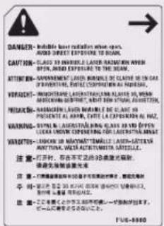
This Product has been classified under IEC60825-1:2007 and EN60825-1:2007, which conform to the following classes;
CLASS 1 LASER PRODUCT
LASER KLASSE 1
APPAREIL Á LASER DE CLASSE 1
APPARECCHIO LASER DI CLASSE 1
PRODUCTO LÁSER DE CLASE 1
APARELHO A LASER DE CLASSE 1
LUOKAN 1 LASER-TUOTE
LASERPRODUKT KLASS 1

CAUTION
Use of controls, adjustments, or performance of procedures other than those specified in the manuals for this machine may result in hazardous radiation exposure.
International ENERGY STAR Program

As an ENERGY STAR® Partner, Canon Inc. has determined that this machine meets the international ENERGY STAR Program for energy efficiency.
The International ENERGY STAR Office Equipment Program is an
international program that promotes energy saving through the use of computers and other office equipment. The program backs the development and dissemination of products with functions that effectively reduce energy consumption. It is an open system in which business proprietors can participate voluntarily. The targeted products are office equipment, such as computers, displays, printers, facsimiles, and copiers. The standards and logos are uniform among participating nations.
IPv6 Ready Logo

text_image
GOLD IR6 READYThe protocol stack included in this machine has obtained the IPv6 Ready Logo Phase-2 established by the IPv6 Forum.
WEEE Directive
European Union (and EEA) only.
These symbols indicate that this product is not to be disposed of with your household waste, according to the WEEE Directive (2002/96/EC), the Battery Directive (2006/66/EC) and/or your national laws implementing those Directives.
If a chemical symbol is printed beneath the symbol shown above, in accordance with the Directive, this indicates that a heavy metal (Hg = Mercury, Cd = Cadmium, Pb = Lead) is present in this battery or accumulator at a concentration above an applicable threshold specified in the Battery Directive.
This product should be handed over to a designated collection point, e.g., on an authorized one-for-one basis when you buy a new similar product or to an authorized collection site for recycling waste electrical and electronic equipment (EEE) and batteries and accumulators.
Improper handling of this type of waste could have a possible impact on the environment and human health due to potentially hazardous substances that are generally associated with EEE.
Your cooperation in the correct disposal of this product will contribute to the effective usage of natural resources.
For more information about the recycling of this product, please contact your local city office, waste authority, approved scheme or your household waste disposal service or visit www.canon-europe.com/environment.
(EEA: Norway, Iceland and Liechtenstein)
R & TTE Directive

This equipment (F190400) conforms with the essential requirements of EC Directive 1999/5/EC and is usable in EU. (Only for models with facsimile functionality.)
(For Europe Only)
Canon Inc./Canon Europa N. V.
Information Security Standard (IEEE 2600)
This machine is compliant with IEEE Std 2600™ - 2008 (hereinafter referred to as IEEE 2600), a global information security standard for multifunction peripherals and printers, and is able to achieve the security requirements defined in IEEE 2600.*
For information on how this machine meets the security requirements defined in IEEE 2600, see e-Manual > Security > IEEE 2600 Security Standard.
* IEEE 2600.1 CC Authentication has not been obtained for this machine.
Copyright
Copyright 2013 by Canon Inc. All rights reserved.
No part of this publication may be reproduced or transmitted in any form or by any means, electronic or mechanical, including photocopying and recording, or by any information storage or retrieval system without the prior written permission of Canon Inc.
This product includes software and/or software modules that are licensed by Canon Inc. or its licensors from third parties. Use and distribution of this software and/or software modules are subject to conditions (a) through (c) below.
(a)
UFST: Copyright © 1989 - 1996, 1997, 2003, 2004, 2008, all rights reserved, by Monotype Imaging Inc.
(b)
Copyright © Unpublished Work of Novell, Inc. All Rights Reserved.
(c)
Portions of this software are copyright © 2007
The FreeType Project (www.freetype.org).
All rights reserved.
Third Party Software
This product includes third-party software modules. Use and distribution of this software modules, including any updates of such software modules (collectively, the "SOFTWARE") are subject to conditions
(1) through (9) below.
(1) You agree that you will comply with any applicable export control laws, restrictions or regulations of the countries involved in the event that this product including the SOFTWARE is shipped, transferred or exported into any country.
(2) Rights holders of the SOFTWARE retain in all respects the title, ownership and intellectual property rights in and to the SOFTWARE. Except as expressly provided herein, no license or right, expressed or implied, is hereby conveyed or granted by rights holders of the SOFTWARE to you for any intellectual property of rights holders of the SOFTWARE.
(3) You may use the SOFTWARE solely for use with the Canon product you purchased (the "PRODUCT").
(4) You may not assign, sublicense, market, distribute, or transfer the SOFTWARE to any third party without prior written consent of rights holders of the SOFTWARE.
(5) Notwithstanding the foregoing, you may transfer the SOFTWARE only when (a) you assign all of your rights to the PRODUCT and all rights and obligations under the conditions to transferee and (b) such transferee agrees to be bound by all these conditions.
(6) You may not decompile, reverse engineer, disassemble or otherwise reduce the code of the SOFTWARE to human readable form.
(7) You may not modify, adapt, translate, rent, lease or loan the SOFTWARE or create derivative works based on the SOFTWARE.
(8) You are not entitled to remove or make separate copies of the SOFTWARE from the PRODUCT.
(9) The human-readable portion (the source code) of the SOFTWARE is not licensed to you.
Notwithstanding (1) through (9) above, in case the other conditions accompany third-party software modules, these software modules are subject to the other conditions.
The Software Subjected to the Other Conditions
Please refer to eManual on a CD-ROM bundled with this product, for more detail and corresponding license conditions.
If you need source code of certain Software, under respective Licenses, used for this product, please send email with the following information in English or Japanese at: oipossg@canon.co.jp
Name of the model that you purchased. -
Product ID number labeled on the back of the main - unit.
Please refer to eManual on a CD-ROM bundled with this product, for more detail and corresponding license conditions.
Disclaimers
The information in this document is subject to change without notice.
CANON INC. MAKES NO WARRANTY OF ANY KIND WITH REGARD TO THIS MATERIAL, EITHER EXPRESS OR IMPLIED, EXCEPT AS PROVIDED HEREIN, INCLUDING WITHOUT LIMITATION, THEREOF, WARRANTIES AS TO MARKETABILITY, MERCHANTABILITY, FITNESS FOR A PARTICULAR PURPOSE OR USE, OR NON-INFRINGEMENT. CANON INC. SHALL NOT BE LIABLE FOR ANY DIRECT, INCIDENTAL, OR CONSEQUENTIAL DAMAGES OF ANY NATURE, OR LOSSES OR EXPENSES RESULTING FROM THE USE OF THIS MATERIAL.
Legal Limitations on the Usage of Your Product and the Use of Images
Using your product to scan, print or otherwise reproduce certain documents, and the use of such images as scanned, printed or otherwise reproduced by your product, may be prohibited by law and may result in criminal and/or civil liability. A non-exhaustive list of these documents is set forth below. This list is intended to be a guide only. If you are uncertain about the legality of using your product to scan, print or otherwise reproduce any particular document, and/or of the use of the images scanned, printed or otherwise reproduced, you should consult in advance with your legal advisor for guidance.
Paper Money •
Travelers Checks •
Money Orders•
Food Stamps •
Certificates of Deposit •
Passports •
Postage Stamps (cancelled or uncancelled)
- Immigration Papers
• Identifying Badges or Insignias - Internal Revenue Stamps (cancelled or uncancelled)
- Selective Service or Draft Papers
• Bonds or Other Certificates of Indebtedness - Checks or Drafts Issued by Governmental Agencies
• Stock Certificates
• Motor Vehicle Licenses and Certificates of Title
• Copyrighted Works/Works of Art without Permission of Copyright Owner
Super G3

Super G3 is a phrase used to describe the new generation of fax machines that use ITU-T V.34 standard 33.6 Kbps* modems. Super G3 High Speed Fax
machines allow transmission times of approximately 3 seconds* per page which results in reduced telephone line charges.
* Approximately 3 seconds per page fax transmission time based on CCITT/ITU-T No.1 Chart, (JBIG, Standard Mode) at 33.6 Kbps modem speed. The Public Switched Telephone Network (PSTN) currently supports 28.8 Kbps modem speeds or slower, depending on telephone line conditions.

NOTE
The fax function is available only if the FAX Board is installed.
Important Safety Instructions
Please read these "Important Safety Instructions" thoroughly before operating the machine. As these instructions are intended to prevent injury to the user or other persons or destruction of property, always pay attention to these instructions. Also, since it may result in unexpected accidents or injuries, do not perform any operation unless otherwise specified in the manual. Improper operation or use of this machine could result in personal injury and/or damage requiring extensive repair that may not be covered under your Limited Warranty.
Installation

WARNING
Never block the ventilation slots and louvers on the machine. These openings are provided for proper ventilation of working parts inside the machine. Blocking these openings can cause the machine to overheat. Never place the machine on a soft surface, such as a sofa or rug.
Do not install the machine in the following • locations:
- A damp or dusty location
- A location near water faucets or water
- A location exposed to direct sunlight
- A location subject to high temperatures
- A location near open flames
Do not install the machine near alcohol, paint • thinner, or other flammable substances. If flammable substances come into contact with electrical parts inside the machine, it may result in a fire or electrical shock.
- Do not place the following items on the machine. If these items come into contact with a high-voltage area inside the machine, it may result in a fire or electrical shock.
If these items are dropped or spilled inside the machine, immediately turn OFF the main power switch, and disconnect the power cord from the power outlet. Then, contact your local authorized Canon dealer.
- Necklaces and other metal objects
- Cups, vases, flowerpots, and other containers filled with water or liquids
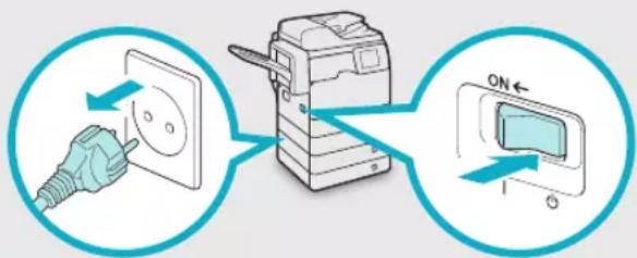
text_image
Diagram showing electrical switch installation with labeled components and directional arrows indicating current flow
CAUTION
Do not install the machine in unstable locations, such as unsteady platforms or inclined floors, or in locations subject to excessive vibrations, as this may cause the machine to fall or tip over, resulting in personal injury.
Power Supply

WARNING
Do not damage or modify the power cord. Also, do not place heavy objects on the power cord, or pull on or excessively bend it, as this could cause electrical damage and result in a fire or electrical shock.
Keep the power cord away from a heat source; failure to do this may cause the power cord coating to melt, resulting in a fire or electrical shock.
Do not connect or disconnect the power cord with wet hands, as this may result in electrical shock.
Do not connect the power cord to a multiplug • power strip, as this may cause a fire or electrical shock.
Do not bundle up or tie the power cord in a knot, as this may result in a fire or electrical shock.
Insert the power plug completely into the power • outlet, as failure to do so may result in a fire or electrical shock.
Do not use power cords other than the power cord provided, as this may result in a fire or electrical shock.
As a general rule, do not use extension cords. Using an extension cord may result in a fire or electrical shock.
Do not use power supplies with voltages other than those specified herein, as this may result in a fire or electrical shock.
Always grasp the power plug when disconnecting the power cord. Pulling on the power cord may expose or snap the core wire, or otherwise damage the power cord. If the power cord is
damaged, this could cause current to leak, resulting in a fire or electrical shock.

IMPORTANT
Leave sufficient space around the power plug so that it can be unplugged easily. If objects are placed around the power plug, you will be unable to unplug it in an emergency.
Handling

WARNING
Do not attempt to disassemble or modify the machine. There are high-temperature and high-voltage components inside the machine which may result in a fire or electrical shock. If the machine makes strange noises, or gives off smoke, heat, or strange smells, immediately turn OFF the main power switch, and disconnect the power cord from the power outlet. Then, contact your local authorized Canon dealer. Continued use of the machine in this condition may result in a fire or electrical shock.
Do not use highly flammable sprays near the machine. If gas from these sprays comes into contact with the electrical components inside the machine, it may result in a fire or electrical shock. To avoid damage to the power cord and creating a fire hazard, always turn OFF the main power switch, and unplug the interface cable when moving the machine. Otherwise, the power cord or interface cable may be damaged, resulting in a fire or electrical shock.
Make sure that the power plug is firmly inserted into the power outlet if the machine was moved. Do not use the machine while the connection is loose, as doing so may cause a fire.
Do not drop paper clips, staples, or other metal objects inside the machine. Also, do not spill water, liquids, or flammable substances (alcohol, benzene, paint thinner, etc.) inside the machine. If these items come into contact with a high-voltage area inside the machine, it may result in a fire or electrical shock. If these items are dropped or spilled inside the machine, immediately turn OFF the main power switch, and disconnect the power cord from the power outlet. Then, contact your local authorized Canon dealer.

CAUTION
Do not place heavy objects on the machine, as they may tip over or fall resulting in personal injury.
Close the feeder gently to avoid catching your hands, as this may result in personal injury.
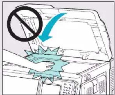
text_image
Diagram illustrating a printer's printing process with a prohibition symbol and a blue arrow indicating removal or disassembly.Do not press down hard on the feeder when using the platen glass to make copies of thick books. Doing so may damage the platen glass and result in personal injury.
Do not touch the finisher while the machine is • printing, as this may result in personal injury. Paper that has just been output from the machine • may be hot. Be careful when removing or aligning paper from the output tray. Touching paper right after it is output may result in low-temperature burns.
Do not place your hands, hair, clothing, etc., near the exit and feed rollers. Even if the machine is not in operation, your hands, hair, or clothing may get caught in the rollers, which may result in personal injury or damage if the machine suddenly starts printing.
Do not place your hands in the part of the tray • where stapling is performed (near the rollers) when a finisher is attached, as this may result in personal injury.
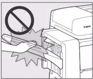
text_image
Diagram showing a hand inserting a printer into a Canon printer with a prohibition symbol above itStaple Finisher-R1
Do not insert your hand into the machine while the paper drawer is removed, as this may result in personal injury.
The laser beam can be harmful to human bodies. • Since radiation emitted inside the product is completely confined within protective housings and external covers, the laser beam cannot escape from the machine during any phase of user operation. Read the following remarks and instructions for safety.
Never open covers other than those instructed in - the manuals for this machine.
Do not remove the following caution label which - is attached to the machine. If the label has been removed, contact your local authorized Canon dealer.
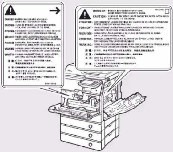
text_image
DANGER - In particular, must be required to use the main components of the device. Aerial or direct capture is not clear. CAUTION - Clear to avoid the laser and prevent which open and can be taken. The device is used to ensure that the laser is an important component of the device. ATTENTION - In particular, it is not clear. It is clear. It is no clear. It is possible. It is difficult. VORNIGHT - In particular, it is not clear. It is difficult. It is possible. It is difficult. FAIRATION - In particular, it is not clear. It is difficult. PROMOTION - In particular, it is not clear. It is difficult. WARNING - In particular, it is not clear. It is difficult. VARIATION - In particular, it is not clear. It is difficult. WARNING - In particular, it is not clear. It is difficult. 注意:对讲,听讲不听讲,听讲不听讲,听讲不听讲。 注意:对讲,听讲不听讲,听讲不听讲,听讲不听讲。 注意:对讲,听讲不听讲,听讲不听讲,听讲不听讲。 注意:对讲,听讲不听讲,听讲不听讲,听讲不听讲。 注意:对讲,听讲不听讲,听讲不听讲,听讲不听讲。 注意:对讲,听讲 不听讲,听讲不听讲,听讲不听讲。 注意:对讲,听讲 不听讲,听讲不听讲,听讲不听讲。 注意:对讲,听讲 不听讲,听讲不听讲,听讲不听讲。 注意:对讲,听讲 不听讲,听讲不听讲,听讲不听讲。 注意:对讲,听讲 不听讲,听讲不听講, 注意:对讲,听讲 不听讲,听讲不听講, 注意:对讲,听讲 不听讲,听讲不听講, 注意:对讲,听讲 不听讲,听讲不听講, 注意:对讲,听讲 不听讲,听讲不听講, 注意:对讲,听讲 不听讲,听讲不听講, 注意:对讲,听讲 不听讲,听讲不开 注意:对讲,听讲 不听讲,听讲不开 注意:对讲,听讲 不听讲,听讲不开 注意:对讲,听讲 不听讲,听讲不开 注意:对讲,听讲 不听讲,听讲不开 注意:对讲,听讲 不听讲,听讲不开 注意:对讲,听讲 不听讲,听讲不开 注意:对进给器、开关和开关的接头、接头、接头、接头、接头、接头、接头、接头、接头、接头、接头、接头、接头、接头、接头、接头、接头、接头、接头、接头、接头、接头、接头、接头、接头、接头、接头、接头、接头、接头、接头、接头、接头、接头、If the laser beam escapes from the machine, - exposure may cause serious damage to your eyes.
Controlling, adjusting, or operating the machine - in ways not mentioned in the manuals for this machine may cause dangerous radiation to escape from the machine.

IMPORTANT
Press (Energy Saver) for safety when the machine will not be used for a long period of time, such as overnight. Also, turn OFF the main power switch, and disconnect the power cord for safety when the machine will not be used for an extended period of time, such as during consecutive holidays.
Maintenance and Inspections

WARNING
When cleaning the machine, first turn OFF the main power switch, then disconnect the power cord. Failure to observe these steps may result in a fire or electrical shock.
Disconnect the power cord from the power outlet • regularly, and clean the area around the base of the power plug's metal pins and the power outlet with a dry cloth to ensure that all dust and grime is removed. If the power cord is connected for a long period of time in a damp, dusty, or smoky location, dust can build up around the power plug and become damp. This may cause a short circuit and result in a fire.
Clean the machine using a slightly dampened cloth with a mild detergent mixed with water. Do not use alcohol, benzene, paint thinner, or other flammable substances. Check detergent for flammability prior to use. If flammable substances come into contact with a high-voltage area inside the machine, it may result in a fire or electrical shock.
There are some areas inside the machine which are subject to high-voltages. When removing jammed paper or when inspecting the inside of the machine, do not allow necklaces, bracelets, or other metal objects to touch the inside of the machine, as this may result in burns or electrical shock.
Do not burn or throw used toner cartridges into open flames, as this may cause the toner remaining inside the cartridges to ignite, resulting in burns or a fire.
Make sure that the power plug is firmly inserted into the power outlet after cleaning the machine. Do not use the machine while the connection is loose, as doing so may cause a fire.
Check the power cord and power plug regularly. If the following conditions occur, contact your local authorized Canon dealer, as the condition may cause a fire:
There are burn marks on the power plug.
The blade on the power plug is deformed or - broken.
The power goes OFF and ON when the power cord is bent.
There are cuts, cracks, or indentations on the power cord.
A part of the power cord becomes hot.
- Check the power cord and power plug regularly to make sure that they are not handled in the following manner, as this may result in a fire or electrical shock:
The connection part of the power plug is loose.
Stress is being applied to the power cord by a - heavy object or by affixing it with staples.
The power plug is loose. -
The power cord is tied in a bundle. -
The power cord protrudes into a walkway. -
The power cord is in front of a heater. -

CAUTION
The fixing unit and its surroundings inside the machine may become hot during use. When removing jammed paper or when inspecting the inside of the machine, do not touch the fixing unit and its surroundings, as doing so may result in burns or electrical shock.
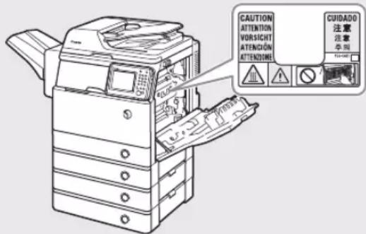
When removing jammed paper or when • inspecting the inside of the machine, do not expose yourself to the heat emitted from the fixing unit and its surroundings for a prolonged period of time. Doing so may result in low temperature burns, even though you did not touch the fixing unit and its surroundings directly. If a paper jam occurs, follow the directions on the • touch panel display to remove any jammed paper from inside the machine. Do not insert your fingers into any parts not indicated on the touch panel display, as doing so may result in personal injury or burns.
When removing jammed paper or replacing the toner cartridge, take care not to allow the toner to come into contact with your hands or clothing, as this will dirty your hands or clothing. If they become dirty, wash them immediately with cold water. Washing them with warm water will set the toner, and make it impossible to remove the toner stains.
When removing paper which has become jammed inside the machine, remove the jammed paper gently to prevent the toner on the paper from scattering and getting into your eyes or mouth. If the toner gets into your eyes or mouth, wash them immediately with cold water and immediately consult a physician.
When removing jammed originals or paper which has become jammed inside the machine, take care not to cut your hands or injure yourself on the edges of the originals or paper. If you cannot
remove the paper, contact your local authorized Canon dealer.
When removing a used toner cartridge, remove the cartridge carefully to prevent the toner from scattering and getting into your eyes or mouth. If the toner gets into your eyes or mouth, wash them immediately with cold water and immediately consult a physician.
- Do not dismantle the toner cartridge, as doing so may cause toner to fly out and enter your eyes or mouth. If toner gets into your eyes or mouth, wash them immediately with cold water and immediately consult a physician.
- If toner escapes from the toner cartridge, make sure not to ingest the toner or allow it to directly touch your skin. If toner touches your skin, wash it away with soap and water. If your skin still feels irritated after washing it, or you ingest toner, consult a doctor immediately.
Consumables

WARNING
- Do not burn or throw used toner cartridges into open flames, as this may cause the toner remaining inside the cartridges to ignite, resulting in burns or a fire.
- Do not store toner cartridges or copy paper in places exposed to open flames, as this may cause the toner or paper to ignite, resulting in burns or a fire.
- If you accidentally spill or scatter toner, carefully gather the toner particles together or wipe them up with a soft, damp cloth in a way that prevents inhalation.
Never use a vacuum cleaner that does not have safeguards against dust explosions to clean up spilled toner. Doing so may cause a malfunction in the vacuum cleaner, or result in a dust explosion due to static discharge.

CAUTION
Keep toner and other consumables out of the • reach of small children. If these items are ingested, consult a physician immediately.
Do not dismantle the toner cartridge, as doing so may cause toner to fly out and enter your eyes or mouth. If toner gets into your eyes or mouth, wash them immediately with cold water and immediately consult a physician.
If toner escapes from the toner cartridge, make sure not to ingest the toner or allow it to directly touch your skin. If toner touches your skin, wash it away with soap and water. If your skin still feels irritated after washing it, or you ingest toner, consult a doctor immediately.
When discarding used toner cartridges, put the • cartridges into a bag to prevent the toner remaining inside the cartridges from scattering, and dispose of them in a location away from open flames.
Other Warnings

WARNING
For cardiac pacemaker users:
This product emits low level magnetic flux. If you use a cardiac pacemaker and feel abnormalities, please move away from the product and consult your doctor.
imageRUNNER ADVANCE 500i/400i Guide de démarrage
Guides de la machine
Directive R & TTE....80
natural_image
Line drawing of a beige office typewriter with front panel and control buttons (no text or symbols)Copyright © 2007-08 Adobe Systems Incorporated. All rights reserved.
Protected by U.S. Patents 5,737,599; 5,781,785; 5,819,301; 5,929,866; 5,943,063; 6,073,148; 6,515,763; 6,639,593; 6,754,382; 7,046,403; 7,213,269; 7,242,415;
Patents pending in the U.S. and other countries.
All instances of the name PostScript in the text are references to the PostScript language as defined by Adobe Systems Incorporated unless otherwise stated. The name PostScript also is used as a product trademark for Adobe Systems' implementation of the PostScript language interpreter.
Except as otherwise stated, any reference to a "PostScript printing device," "PostScript display device," or similar item refers to a printing device, display device or item (respectively) that contains PostScript technology created or licensed by Adobe Systems Incorporated and not to devices or items that purport to be merely compatible with the PostScript language.
Adobe, the Adobe logo, PostScript, the PostScript logo, and PostScript 3 are either registered trademarks or trademarks of Adobe Systems Incorporated in the United States and/or other countries.
Linux is a registered trademark of Linus Torvalds. Microsoft and Windows are either registered trademarks or trademarks of Microsoft Corporation in the United States and/or other countries.
All other trademarks are the property of their respective owners.

text_image
Adobe® PDFCopyright © 2008 Adobe Systems Incorporated. All rights reserved.
Protected by U.S. Patents 6,185,684; 6,205,549; 7,213,269; 7,272,628; 7,278,168; Patents pending in the U.S. and other countries.
All instances of the name PostScript in the text are references to the PostScript language as defined by Adobe Systems Incorporated unless otherwise stated. The name PostScript also is used as a product trademark for Adobe Systems' implementation of the PostScript language interpreter.
Except as otherwise stated, any reference to a "PostScript printing device," "PostScript display device,"
or similar item refers to a printing device, display device or item (respectively) that contains PostScript technology created or licensed by Adobe Systems Incorporated and not to devices or items that purport to be merely compatible with the PostScript language.
Adobe, the Adobe logo, PostScript, the PostScript Logo, and PostScript 3 are either registered trademarks or trademarks of Adobe Systems Incorporated in the United States and/or other countries.
All other trademarks are the property of their respective owners.
natural_image
Illustration of a printer with two circular insets showing mechanical components (no text or symbols)natural_image
Illustration of a printer with a circular frame and light rays, no text or symbols present.natural_image
Illustration of a printer with a diagonal line crossing through it, set against a circular background (no text or symbols)natural_image
Illustration of a portable device emitting smoke from two bottles, enclosed in a circular frame (no text or symbols)natural_image
Illustration of a stack of paper sheets with a diagonal line, no text or symbols presenttext_image
Diagram showing a thermometer measuring a device, enclosed in a circular prohibition symbol.natural_image
Illustration of a hand using a computer to switch a device, with no visible text or symbolsnatural_image
Illustration of a printer with two stacks of boxes, no text or symbols presentnatural_image
Illustration of a hand holding a pen inside a prohibition symbol (no text or symbols present)natural_image
Symbolic illustration of a crossed-out envelope with scissors and paperclip, enclosed in a circle (no text or symbols)text_image
Diagram illustrating the connection between an electrical outlet, a switch, and a display with ON/OFF indicators.natural_image
Illustration of a hand pouring liquid from a spray bottle into a stack of boxes (no text or symbols)natural_image
Illustration of a printer with a magnified view showing its screen and keypad (no text or symbols present)natural_image
Two identical 3D rectangular panels with horizontal slats, no text or symbols visible
natural_image
Simple line drawing of a rectangular object with horizontal lines and rounded edges (no text or symbols)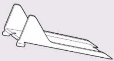
natural_image
Simple line drawing of a mechanical support or bracket (no text or symbols)natural_image
Technical line drawing of a mechanical component with an inset showing a close-up view of internal components (no text or symbols)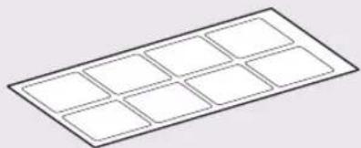
natural_image
Pure diagram of a rectangular grid with eight empty squares, no text or symbols present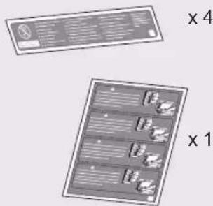
text_image
x 4 x 1natural_image
Line drawing of a cable with two connectors, one connected to an electrical outlet (no text or symbols)
natural_image
Circular object with a central hole and a label 'x 7' on the side (no other text or symbols)
natural_image
Stack of three books with a light blue cover and wavy lines, no visible text or symbols on the covers.text_image
Illustration of a generic document layout with text blocks and a header, framed in a blue border.natural_image
Illustration of two electronic devices with heat sinks and ventilation system (no text or symbols)natural_image
Illustration of a printer with an open lid and directional arrows indicating motion (no text or symbols)natural_image
Diagram of a device panel with buttons and ventilation grilles, no text or symbols presentnatural_image
Illustration of a printer with a paper feed and a blue arrow indicating print direction (no text or symbols)text_image
Diagram showing a no-smoking sign with a prohibition symbol, indicating no smoking or no smoking in a vehicle.
IMPORTANT
natural_image
Line drawing of a printer with a green download arrow indicating the paper's edge (no text or symbols present)text_image
Diagram showing a printer with two labeled parts (1 and 2) indicating directional changes in the device's operation.natural_image
Illustration of a printer's door panel with a hand inserting a blue arrow (no text or symbols)natural_image
Diagram of a printer internal structure with a magnified view showing a mechanical component (no text or symbols)natural_image
Diagram of a mechanical device inside a container with a blue arrow indicating motion (no text or symbols)text_image
Diagram showing a device's internal components with an arrow indicating rotation and a numbered label '1' pointing to a specific component.natural_image
Diagram of a vehicle engine compartment showing internal components and a blue arrow indicating a specific part (no text or symbols present)07
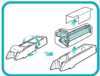
natural_image
Diagram showing three stages of a mechanical assembly with arrows indicating motion (no text or symbols)[Non-Text]
![CANON imageRUNNER ADVANCE 400i - [Non-Text] - 1](/content/2026/04/666717/images/904838a20dda69bf5567d6e02b38d735ff16dbae80f94db86e0d24a69b777f83.jpg)
natural_image
Illustration of a hand holding a cylindrical device with a prohibition symbol (no text or labels)natural_image
Diagram of a mechanical device with motion arrows indicating movement, no text or symbols presentnatural_image
Mechanical assembly diagram showing hands operating a bracket with two circular insets highlighting the components (no text or symbols present)text_image
Diagram showing a device's internal components with a magnified view highlighting a component labeled '1'natural_image
Diagram of a mechanical device interior showing internal components and a blue arrow indicating direction (no text or symbols)natural_image
Technical line drawing of a printer internal structure with no visible text or symbolsnatural_image
Illustration of a hand pressing down on a computer interface with a blue arrow indicating action (no text or symbols present)natural_image
Simple line drawing of a mechanical component with a curved arrow indicating direction (no text or symbols)Retirer la cartouche de toner de son emballage de protection.
03
![CANON imageRUNNER ADVANCE 400i - [Non-Text] - 2](/content/2026/04/666717/images/2f8ccfef123461f1588187f1e5277dd8c8bfda477c9542f48e0a7333b4df0dd5.jpg)
natural_image
Illustration of a mechanical component with a rotating arrow indicating rotation (no text or symbols)Retirer le bouchon de protection.
![CANON imageRUNNER ADVANCE 400i - [Non-Text] - 3](/content/2026/04/666717/images/4b0f64885ff49f07a1780b0f6c9c274e744aa5838862047b5c685e9acbd3b36b.jpg)
natural_image
Illustration of a hand holding a plug with a no-smoking symbol (no text or labels)![CANON imageRUNNER ADVANCE 400i - [Non-Text] - 4](/content/2026/04/666717/images/c8efb47140b251811a01533d73e02843ef3f4674e3355a14fc33229b26e9b6de.jpg)
IMPORTANT
natural_image
Illustration of a printer's internal mechanism with a blue arrow indicating the process (no text or symbols present)natural_image
Diagram of a printer internal structure with a blue arrow indicating a component (no text or symbols present)05
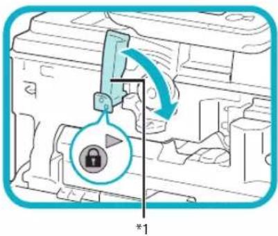
text_image
Diagram showing a mechanical component with a lock icon and directional arrow, labeled with dimension marker *1text_image
Diagram of a printer internal structure with labeled parts and directional arrows indicating assembly or movement.Fermer le capot avant.
natural_image
Line drawing of a hand pressing a button on a computer monitor (no text or symbols)natural_image
Illustration of a printer being inserted into a plastic case, showing the printer's internal structure and a blue arrow indicating the process (no text or symbols present)text_image
Diagram showing a computer system with labeled components and directional arrows indicating movement or flow.natural_image
Illustration of two hands folding a folded paper with a diagonal line crossing (no text or symbols)natural_image
Illustration of a hand inserting a blue card into a device (no text or symbols visible)natural_image
Illustration of a hand inserting a printer into a slot, showing the printer's internal structure and an arrow indicating motion (no text or symbols present)natural_image
Simple line drawing of a grid layout with a highlighted rectangular area (no text or symbols)natural_image
Illustration of a printer with a magnified view of a paper sheet (no text or symbols)natural_image
Illustration of a printer with an open lid and a blue arrow indicating the process (no text or symbols present)Ouvrir le chargeur.
02
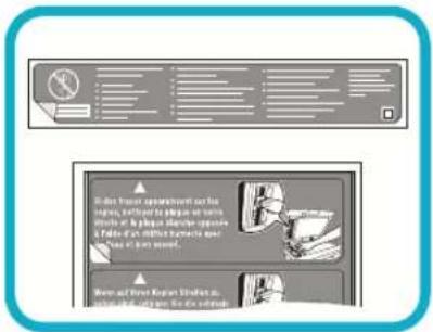
text_image
I don't know about what is, I think, I'll be able to get and you're going to the you're going to the you're going to the you're going to the you're going to the you're going to the you're going to the you're going to the you're going to the you're going to the you're going to the you're going to the you're going to the you're going to the you're going to the you're going to the you're going to the you're going to you're going to the you're going to the you're going to the you're going to the you're going to the you're going to the you're going to the you're going to the you're going to the you're going to the you're going to the you're going to the you're going to the you're going to the you're going to the you're going to the you're You're going to the you're going to the you're going to the you're going to the you're going to the you're going to the you're going to the you're going to the you're going to the you're going to the you're going to the you're going to the you're going to the you're going to the you're going to the you're going to the you're going totext_image
Diagram of a printer with labeled parts and UI elements, showing front panel layout and internal components.natural_image
Illustration of an open printer with a blue arrow indicating compression or disassembly (no text or symbols present)natural_image
Line drawing of a printer with a cable and power outlet, no text or symbols presentnatural_image
Illustration of a printer with a scroll and a screen, connected to a handheld device (no text or symbols present)
REMARQUE
text_image
Diagram showing a printer with an ON/OFF switch and its screen, illustrating the process of press or print operation.
IMPORTANT
natural_image
Pure technical diagram of a mechanical component with no text, numbers, or symbolstext_image
Diagram of a printer with labeled parts including a door panel, printer, and printer unittext_image
Technical diagram of a printer with numbered parts and internal connector labelstext_image
Technical diagram of an open printer with numbered parts labeled for identificationtext_image
Technical diagram of a device with numbered parts, showing exploded and assembled views of the device.1 Capot du chargeur
15 [Suivi statut/Annulation]
natural_image
Diagram of a device's rear panel with directional arrows indicating movement, no text or symbols presentImportation/Exportation totale
Importation/Exportation individuelle•
text_image
Diagram showing a printer device with labeled parts, including a close-up view of the internal structure.natural_image
Illustration showing two hands folding a folded paper with a blue diagonal line (no text or symbols)text_image
Diagram showing a printer with labeled parts and directional arrows indicating assembly or operation.text_image
Diagram showing a printer with labeled parts and directional arrows indicating process flow or assembly steps.text_image
Diagram showing printer internal structure with labeled components and directional arrows indicating process flowtext_image
Diagram showing a printer's internal structure with labeled components, including a zoomed-in view of the component.text_image
Diagram showing a printer device with labeled parts and directional arrows indicating assembly or operation.natural_image
Illustration of a printer next to a computer with a magnified inset showing a geometric shape (no text or symbols)![CANON imageRUNNER ADVANCE 400i - [Suivi statut/Annulation] - 1](/content/2026/04/666717/images/a22c3c15740b999f61f116d029e575867c5a4622f7bc55c07368fd1c3f27874b.jpg)
IMPORTANT
text_image
Diagram showing a printer with blue ribbon and two labeled parts, illustrating the process of inserting or removing a device.text_image
Diagram illustrating a file transfer or locking mechanism with labeled components and directional arrowsnatural_image
Illustration of a printer with a magnified view of its internal structure (no text or symbols)natural_image
Simple line drawing of a cylindrical object with a pointed tip and a small inset component, no text or symbols present.natural_image
Diagram of a mechanical component with a rotating arrow indicating rotation (no text or symbols)natural_image
Illustration of a hand holding a plug with a no-smoking symbol (no text or labels)natural_image
Illustration of a printer with a magnified view showing internal components (no text or symbols)
REMARQUE
text_image
Diagram illustrating a printer's internal mechanism with lock and padlock operation, showing a printer's open position and lock mechanism.text_image
Diagram showing a printer with labeled parts and directional arrows indicating process flow or movement.text_image
Diagram showing a printer with blue arrows indicating two steps: one to press or attach the printer, and another to press or install the device.text_image
Diagram illustrating a printer's internal structure with an arrow indicating a component or operation, accompanied by a magnified view of the printer's internal structure.natural_image
Diagram showing a printer with a blue cover and internal components, no text or symbols present
ATTENTION
natural_image
Technical illustration of a mechanical assembly with a magnified inset showing internal components (no text or symbols)05
natural_image
Illustration of a hand holding a document with a blue arrow indicating direction (no text or symbols present)
REMARQUE
natural_image
Illustration of a cable or wire package with internal components (no text or symbols)natural_image
Diagram showing a printer with internal components and an open door, no text or symbols presenttext_image
Diagram illustrating a printer's internal structure and its application in a device, with magnified view of the printer's internal components.text_image
Diagram showing a printer with labeled parts and directional arrows indicating process flow or movement.text_image
Diagram showing a printer with blue tape and two labeled parts, illustrating the process of inserting or removing a device.natural_image
Illustration of a printer and its internal door mechanism (no text or symbols)natural_image
Illustration of a printer with a magnified view showing internal components (no text or symbols)
IMPORTANT
text_image
Diagram showing a printer file being inserted into an open storage unit, with a magnified view highlighting the internal structure.natural_image
Diagram showing a printer with a blue arrow pointing to a mechanical component inside a machine (no text or symbols present)
ATTENTION
natural_image
Technical illustration of a mechanical assembly with a magnified inset showing internal components (no text or symbols)text_image
Diagram showing a printer with a magnified view of the internal components, highlighting a device's component.text_image
Diagram illustrating a printer's internal structure with a magnified view showing the component being inserted into a machine.*:repère bleu
text_image
Diagram illustrating a printer's internal structure and tool path, showing hand positioning and tool insertion steps.Retirer le tambour de son film de protection.
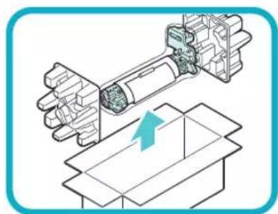
natural_image
Technical illustration of a robotic arm interacting with a box, showing mechanical components and a blue arrow indicating motion (no text or symbols present)
IMPORTANT
natural_image
Illustration of a hand holding a cylindrical device with a prohibition symbol (no text or labels)natural_image
Diagram of a mechanical device with motion arrows indicating movement, no text or symbols presenttext_image
Diagram illustrating a printer's internal structure and tool path, showing hand positioning and tool application steps.text_image
Diagram showing printer operation with magnified view of device and component detailsnatural_image
Technical illustration of a mechanical assembly with an inset showing a close-up of a component (no text or symbols present)-

IMPORTANT
natural_image
Diagram showing a printer with internal components and a magnified view of the device (no text or symbols present)text_image
Diagram showing a printer with a magnified view of internal components, highlighting a hand holding a green object with an arrow.natural_image
Illustration of a printer being inserted into a machine, showing the printer's internal structure and the printer's side panel (no text or symbols present)
ATTENTION
text_image
Diagram showing a printer with labeled parts and directional arrows indicating process flow or movement.text_image
Diagram showing a printer with labeled parts, including a folder and an open device with two labeled parts.natural_image
Diagram showing a printer device and its internal structure, with no visible text or symbolsnatural_image
Technical illustration of a printer with internal components and a magnified view of the cover (no text or symbols)
natural_image
Diagram showing a printer device and its internal components, no text or symbols presentnatural_image
Technical illustration of a printer holder and internal components (no text or symbols)natural_image
Technical line drawing of a printer with an arrow pointing to its front panel (no text or symbols present)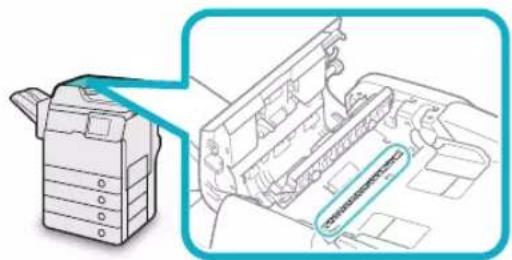
natural_image
Technical line drawing of a printer with an inset view showing internal components (no text or symbols)natural_image
Illustration of a printer with an open lid and a magnified view showing the lid being inserted (no text or symbols present)natural_image
Illustration of a printer with a close-up view of its open lid (no text or symbols present)natural_image
Illustration of a printer being placed on top, showing the printer's lid and handle (no text or symbols present)natural_image
Illustration of a printer with a magnified inset showing internal components (no text or symbols)natural_image
Illustration of a printer with a paper feeding into a stackable device (no text or symbols visible)
ATTENTION
natural_image
Illustration of a printer with a blue arrow indicating the open lid (no text or symbols present)
ATTENTION
natural_image
Diagram showing a printer device with an open circuit board and its internal components, no text or symbols present.
ATTENTION
natural_image
Line drawing of a cylindrical mechanical component with internal grooves and a triangular feature (no text or symbols)
AVERTISSEMENT
natural_image
Technical illustration of a mechanical component with no visible text or symbolstext_image
Install Application Course To install the classifier application, a license for most of the software. Specify a server file SaveCLASS 1 LASER PRODUCT
LASER KLASSE 1
APPAREIL Á LASER DE CLASSE 1
APPARECCHIO LASER DI CLASSE 1
PRODUCTO LÁSER DE CLASE 1
APARELHO A LASER DE CLASSE 1
LUOKAN 1 LASER-TUOTE
LASERPRODUKT KLASS 1
ATTENTION
UFST: Copyright © 1989 - 1996, 1997, 2003, 2004, 2008, all rights reserved, by Monotype Imaging Inc.
(b)
Copyright © Unpublished Work of Novell, Inc.
All Rights Reserved.
(c)
Portions of this software are copyright © 2007
The FreeType Project(www.freetype.org).
All rights reserved.
text_image
Diagram showing electrical connection with a plug, switch, and screen, labeled with ON/OFF states
ATTENTION
text_image
Diagram showing a printer with a prohibition symbol overlay and a hand holding a paper, indicating no printing or anti-printing.text_image
Diagram showing a printer with a prohibition symbol and a hand inserting paper into the printer's main page, labeled 'Cable'Module de Finition agrafage-R1
natural_image
Line drawing of a legacy office typewriter with multiple drive bays and a central display (no text or symbols)Copyright © 2007 -08 Adobe Systems Incorporated. All rights reserved.
Protected by U.S. Patents 5,737,599; 5,781,785; 5,819,301; 5,929,866; 5,943,063; 6,073,148; 6,515,763; 6,639,593; 6,754,382; 7,046,403; 7,213,269; 7,242,415; Patents pending in the U.S. and other countries.
All instances of the name PostScript in the text are references to the PostScript language as defined by Adobe Systems Incorporated unless otherwise stated. The name PostScript also is used as a product trademark for Adobe Systems' implementation of the PostScript language interpreter.
Except as otherwise stated, any reference to a "PostScript printing device," "PostScript display device," or similar item refers to a printing device, display device or item (respectively) that contains PostScript technology created or licensed by Adobe Systems Incorporated and not to devices or items that purport to be merely compatible with the PostScript language.
Adobe, the Adobe logo, PostScript, the PostScript logo, and PostScript 3 are either registered trademarks or trademarks of Adobe Systems Incorporated in the United States and/or other countries.
Linux is a registered trademark of Linus Torvalds. Microsoft and Windows are either registered trademarks or trademarks of Microsoft Corporation in the United States and/or other countries.
All other trademarks are the property of their respective owners.

text_image
Adobe® PDFCopyright © 2008 Adobe Systems Incorporated. All rights reserved.
Protected by U.S. Patents 6,185,684; 6,205,549;
7,213,269; 7,272,628; 7,278,168; Patents pending in the U.S. and other countries.
All instances of the name PostScript in the text are references to the PostScript language as defined by Adobe Systems Incorporated unless otherwise stated. The name PostScript also is used as a product trademark for Adobe Systems' implementation of the PostScript language interpreter.
Except as otherwise stated, any reference to a "PostScript printing device," "PostScript display device," or similar item refers to a printing device, display device or item (respectively) that contains PostScript technology created or licensed by Adobe Systems Incorporated and not to devices or items that purport to be merely compatible with the PostScript language.
Adobe, the Adobe logo, PostScript, the PostScript Logo, and PostScript 3 are either registered trademarks or trademarks of Adobe Systems Incorporated in the United States and/or other countries.
All other trademarks are the property of their respective owners.
natural_image
Illustration of a printer with two circular insets showing different devices (no text or symbols)natural_image
Illustration of a printer with a magnifying glass, enclosed in a circular frame (no text or symbols)natural_image
Illustration of a printer with a spool, enclosed in a circular frame (no text or symbols)natural_image
Illustration of a suitcase with three bottles and a hand holding a bottle, enclosed in a circular frame (no text or symbols)natural_image
Illustration of a printer with a spool and paper plane, enclosed in a circular frame (no text or symbols)text_image
Diagram showing a thermometer measuring a printer, with a circular prohibition symbol indicating no protection.natural_image
Illustration of a hand using a tool to switch from a computer to a device, with no visible text or symbols.natural_image
Illustration of a printer with two stacks of boxes, no text or symbols presentnatural_image
Illustration of a hand holding a tool inside a device, enclosed in a circular frame (no text or symbols)natural_image
Prohibition symbol with a paperclip, scissors, and eraser inside a circle (no text or symbols)text_image
Diagram illustrating the connection between a power plug, a device, and an open screen with ON/OFF indicators.natural_image
Illustration of a hand pouring liquid from a container onto a stack of boxes, enclosed in a circular frame (no text or symbols)natural_image
Illustration of a printer with a magnified view showing its screen and keypad (no text or symbols present)text_image
Illustration of a generic document layout with text blocks and a header, framed in a blue border.natural_image
Illustration of two electronic devices with heat exchangers and ventilation ducts (no text or symbols)natural_image
Illustration of a printer with open lid and control panel, showing mechanical operation (no text or symbols)natural_image
Diagram of a device panel with buttons and ventilation grilles, no text or symbols presentnatural_image
Illustration of a printer with a paper feed and a green arrow indicating print direction (no text or symbols)text_image
Safety warning sign with Chinese text indicating no hazard, featuring a blue rectangular object on a vehicle.
WICHTIG
natural_image
Illustration of a printer with a paper feed insert, showing internal compartments and a blue arrow indicating the process (no text or symbols present)text_image
Diagram showing a printer with two labeled parts, indicating press or download actions with arrows and numbered indicators.natural_image
Illustration of a hand pressing down on a printer's side panel with a blue arrow indicating the process (no text or symbols present)natural_image
Diagram of a printer internal structure with a magnified view showing a mechanical component (no text or symbols)natural_image
Diagram of a mechanical device interior showing internal components and a blue arrow indicating direction (no text or symbols)text_image
Technical diagram showing a mechanical device with a magnified inset highlighting a component, labeled with dimension marker '1'natural_image
Diagram of a device internal structure with a blue arrow indicating a component (no text or symbols present)07
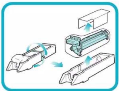
natural_image
Diagram showing three stages of a mechanical assembly with arrows indicating motion (no text or symbols)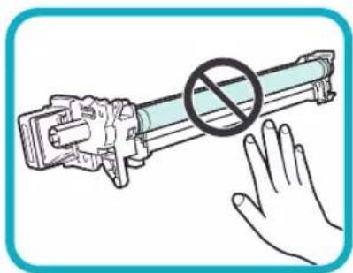
natural_image
Illustration of a hand holding a cylindrical device with a prohibition symbol (no text or labels)natural_image
Diagram of a mechanical device with rotating components and directional arrows indicating motion (no text or symbols)natural_image
Illustration of hands operating a mechanical device with two views of the mechanism (no text or symbols present)text_image
Diagram showing a device's internal components with a magnified view highlighting a component being inserted, labeled with part number *1.natural_image
Diagram of a mechanical device interior showing internal components and a blue arrow indicating direction (no text or symbols)natural_image
Diagram of a printer internal structure with a magnified view showing internal components and a numbered label (1), no readable text or symbols present.natural_image
Illustration of a hand pressing down on a computer interface with a blue arrow indicating action (no text or symbols present)natural_image
Simple line drawing of a cylindrical object with a pointed tip and a curved arrow indicating direction (no text or symbols)natural_image
Diagram of a mechanical component with a rotating shaft and arrow indicating rotation (no text or symbols)natural_image
Illustration of a hand holding a connector with a no-smoking symbol (no text or labels)
WICHTIG
natural_image
Illustration of a hand inserting a device into a printer case (no text or symbols visible)natural_image
Diagram of a printer's internal structure showing a green cover with a blue arrow indicating the component (no text or symbols present)05

text_image
Diagram showing a lock mechanism with directional arrows and a labeled component, marked with a symbol *1text_image
Diagram of a printer internal structure with labeled parts 1, 2, and directional arrows indicating flow or movement.natural_image
Line drawing of a hand pressing a button on a computer device (no text or symbols)natural_image
Illustration of a printer being inserted into a plastic case, with a hand pointing to the component (no text or symbols present)natural_image
Illustration showing two hands folding or holding a folded paper, separated by a diagonal line (no text or symbols)natural_image
Illustration of a hand inserting a plastic into a device into a housing (no text or symbols visible)natural_image
Illustration of a hand inserting a printer into a plastic case (no text or symbols visible)natural_image
Simple line drawing of a grid layout with a highlighted rectangular area (no text or symbols)natural_image
Illustration of a printer with a magnified view of a paper clip (no text or symbols)natural_image
Illustration of a printer with an open lid and a blue arrow indicating the open lid area (no text or symbols present)text_image
Scanned document page with Chinese text and two embedded diagrams showing mechanical components.text_image
Diagram of a printer with labeled parts and UI elements, showing front panel layout and control buttons.natural_image
Illustration of an open printer with a blue arrow indicating the open lid (no text or symbols present)natural_image
Line drawing of a printer connected to a power outlet (no text or symbols)natural_image
Illustration of a printer with a magnified view of its screen and keypad (no text or symbols present)
HINWEIS
text_image
Diagram showing a printer with an ON/OFF switch and a screen with directional arrows, illustrating the process.
WICHTIG
natural_image
Pure technical diagram of a mechanical component with no text, numbers, or symbolstext_image
Diagram of a printer with labeled parts including a door panel, printer, and printer unit, showing internal components and connection points.text_image
Technical diagram of a printer with numbered parts and internal connector labels1 Hauptschalter
text_image
Technical diagram of an open printer with numbered parts labeled for identificationtext_image
① ② ③ ④ Cable
text_image
Technical diagram of a printer or scanner with labeled parts, showing open lid and internal structure.15 [Status Monitor/Abbruch]
natural_image
Diagram of a device with a curved arrow indicating rotation or movement, showing no text or symbols present.*1: Justierbereich
![CANON imageRUNNER ADVANCE 400i - [Status Monitor/Abbruch] - 1](/content/2026/04/666717/images/767e67546ff99a2f7885598bc32ee55086299060cb282f3b261919afaa6c7314.jpg)
WICHTIG
text_image
Diagram showing a printer device with labeled parts and directional arrows indicating assembly or operation.natural_image
Illustration showing two hands folding a folded paper with a blue diagonal line (no text or symbols)text_image
Diagram showing a printer with labeled parts and directional arrows indicating assembly or operation.text_image
Diagram showing a printer with labeled parts and directional arrows indicating process flow or movement.text_image
Diagram illustrating printer internal structure with labeled components and directional arrows, including annotations *1 and *2.*1: Hebel
*2: Seitenführung
text_image
Diagram showing printer internal structure with labeled components and directional arrows indicating movement or assembly.*1:Hebel
*2: Vordere Führung
text_image
Diagram showing a printer device with labeled parts and directional arrows indicating assembly or operation.natural_image
Illustration of a printer next to a computer with a magnified inset showing a geometric shape (no text or symbols)
WICHTIG
text_image
Diagram showing printer operation with labeled parts and directional arrows indicating process flowtext_image
Diagram illustrating a printer's internal mechanism with lock and padlock, showing process steps and component placement.natural_image
Illustration of a printer with a magnified view showing internal components (no text or symbols)natural_image
Simple line drawing of a cylindrical object with a pointed tip and a curved arrow indicating direction (no text or symbols)natural_image
Diagram of a mechanical component with a rotating arrow indicating rotation (no text or symbols)natural_image
Illustration of a hand holding a connector with a no-smoking symbol (no text or labels present)natural_image
Illustration of a printer and a cylindrical device inside a mechanical housing (no text or symbols)
HINWEIS
text_image
Diagram illustrating a printer's internal structure and lock mechanism, showing paper feeding into a device with a lock icon and lock symbol.text_image
Diagram showing a printer with labeled parts and directional arrows indicating process flow or movement.text_image
Diagram showing printer operation with labeled parts and directional arrows indicating process flowtext_image
Diagram showing printer operation with labeled parts and a magnified view of the printer's internal structure.natural_image
Diagram showing a printer with internal components and a magnified view of the device (no text or symbols present)
VORSICHT
natural_image
Technical illustration of a mechanical assembly with a magnified inset showing internal components (no text or symbols)natural_image
Illustration of a cable connector with internal insulation and tape (no text or symbols)natural_image
Diagram showing a printer with a highlighted internal component, no text or symbols presenttext_image
Diagram showing a printer with internal components and a magnified view of the device's internal structure, labeled with an asterisk.text_image
Diagram showing a printer with labeled parts and directional arrows indicating process flowtext_image
Diagram showing printer operation with labeled parts and directional arrows indicating process flownatural_image
Illustration of a printer next to an open microwave oven, showing the device's internal structure (no text or symbols present)natural_image
Illustration of a printer and its internal structure, showing part assembly (no text or symbols)
WICHTIG
text_image
Diagram illustrating a printer's internal structure with a magnified view showing the printer's internal components and a component labeled with an asterisk.natural_image
Diagram showing a printer with a blue cover and internal structure, no text or symbols present
VORSICHT
natural_image
Technical illustration of a mechanical assembly with a magnified inset showing internal components (no text or symbols)06
text_image
Diagram illustrating printer operation with magnified view of internal components and a close-up of the printer's internal structure.text_image
Diagram illustrating a printer's internal structure with a hand inserting a component, showing a magnified view of the part.*: Blaue Markierung
text_image
Diagram illustrating a printer's internal structure and tool path, showing hand positioning and alignment instructions.natural_image
Technical illustration of a robotic arm interacting with a box, showing mechanical components and a blue arrow indicating motion (no text or symbols present)
WICHTIG
natural_image
Illustration of a hand holding a cylindrical device with a prohibition symbol (no text or labels)natural_image
Diagram of a mechanical device with motion arrows indicating movement, no text or symbols presenttext_image
Diagram illustrating a printer's internal structure and assembly process, with magnified views highlighting the components.text_image
Diagram showing printer operation with magnified view of internal components and a warning symbolnatural_image
Technical illustration of a mechanical assembly with a magnified inset showing internal components (no text or symbols)
WICHTIG
natural_image
Diagram showing a printer with a blue cover and internal components, no text or symbols presenttext_image
Diagram showing a printer with internal components and a magnified view of a device's internal structure, likely illustrating a printing or assembly process.natural_image
Illustration of a printer and its internal device with a blue arrow indicating rotation (no text or symbols present)
VORSICHT
text_image
Diagram showing a printer with labeled parts and directional arrows indicating process flow or movement.text_image
Diagram showing a printer with labeled parts, including a 2D view and an open base.natural_image
Diagram showing a printer device and its internal component, with no visible text or symbolstext_image
Technical diagram showing two views of a printer's internal structure with labeled parts and highlighted sections.natural_image
Technical line drawing of a printer holder and internal components (no text or symbols)text_image
Technical diagram showing two views of a printer's internal structure with Chinese annotations indicating parts of the printer's interior and exterior.natural_image
Illustration of a printer with an open lid and a blue arrow indicating the process (no text or symbols present)natural_image
Illustration of a printer with a magnified view showing internal components (no text or symbols)natural_image
Illustration of a printer being placed on top of a printer, showing the blade being cut with a magnified view (no text or symbols)natural_image
Illustration of a printer with a magnified inset showing internal components (no text or symbols)natural_image
Illustration of a printer with a paper feeding into a stackable machine (no text or symbols visible)VORSICHT
natural_image
Illustration of a printer with a magnified view showing the open lid (no text or symbols present)VORSICHT
natural_image
Diagram showing a printer device being inserted into a mechanical component, with no visible text or symbols.VORSICHT
natural_image
Line drawing of a cylindrical mechanical component with threaded ends and a triangular feature on the side (no text or symbols)
WARNUNG
natural_image
Technical line drawing of a mechanical component with no visible text or symbolstext_image
Install Equation(s)ense To install the query function: a formula for query solution of the queries. Specify, please write SaveCLASS 1 LASER PRODUCT
LASER KLASSE 1
APPAREIL Á LASER DE CLASSE 1
APPARECCHIO LASER DI CLASSE 1
PRODUCTO LÁSER DE CLASE 1
APARELHO A LASER DE CLASSE 1
LUOKAN 1 LASER-TUOTE
LASERPRODUKT KLASS 1
VORSICHT
UFST: Copyright © 1989 - 1996, 1997, 2003, 2004, 2008, all rights reserved, by Monotype Imaging Inc.
(b)
Copyright © Unpublished Work of Novell, Inc. All Rights Reserved.
(c)
Portions of this software are copyright © 2007 The FreeType Project (www.freetype.org).
All rights reserved.
text_image
Diagram showing electrical connection with a plug, switch, and screen, labeled with ON/OFF states
VORSICHT
text_image
Diagram showing a printer with a 'No' symbol and a blue arrow indicating removal or disassembly, suggesting a machine operation.text_image
Diagram showing a printer with a prohibition symbol and a hand holding a paper, indicating no printing or disassembly.Finisher R1
natural_image
Line drawing of a generic electronic device with multiple ports and control panels (no text or symbols)Copyright © 2007 -08 Adobe Systems Incorporated. All rights reserved.
Protected by U.S. Patents 5,737,599; 5,781,785; 5,819,301; 5,929,866; 5,943,063; 6,073,148; 6,515,763; 6,639,593; 6,754,382; 7,046,403; 7,213,269; 7,242,415; Patents pending in the U.S. and other countries.
All instances of the name PostScript in the text are references to the PostScript language as defined by Adobe Systems Incorporated unless otherwise stated.
The name PostScript also is used as a product trademark for Adobe Systems' implementation of the PostScript language interpreter.
Except as otherwise stated, any reference to a "PostScript printing device," "PostScript display device," or similar item refers to a printing device, display device or item (respectively) that contains PostScript technology created or licensed by Adobe Systems Incorporated and not to devices or items that purport to be merely compatible with the PostScript language.
Adobe, the Adobe logo, PostScript, the PostScript logo, and PostScript 3 are either registered trademarks or trademarks of Adobe Systems Incorporated in the United States and/or other countries.
Linux is a registered trademark of Linus Torvalds. Microsoft and Windows are either registered trademarks or trademarks of Microsoft Corporation in the United States and/or other countries.
All other trademarks are the property of their respective owners.

text_image
Adobe® PDFCopyright © 2008 Adobe Systems Incorporated. All rights reserved.
Protected by U.S. Patents 6,185,684; 6,205,549; 7,213,269; 7,272,628; 7,278,168; Patents pending in the U.S. and other countries.
All instances of the name PostScript in the text are references to the PostScript language as defined by Adobe Systems Incorporated unless otherwise stated. The name PostScript also is used as a product trademark for Adobe Systems' implementation of the PostScript language interpreter.
Except as otherwise stated, any reference to a "PostScript printing device," "PostScript display device," or similar item refers to a printing device, display device or item (respectively) that contains PostScript technology created or licensed by Adobe Systems Incorporated and not to devices or items that purport to be merely compatible with the PostScript language.
Adobe, the Adobe logo, PostScript, the PostScript Logo, and PostScript 3 are either registered trademarks or trademarks of Adobe Systems Incorporated in the United States and/or other countries.
All other trademarks are the property of their respective owners.
natural_image
Illustration of a printer with two circular insets showing mechanical components (no text or symbols)natural_image
Illustration of a printer with a magnifying glass emitting light, enclosed in a circular frame (no text or symbols)natural_image
Illustration of a printer with a diagonal line crossing through it, set against a textured circular background (no text or symbols)natural_image
Illustration of a chemical processing machine with two bottles and a dashed line indicating a chemical reaction or safety symbol (no text or labels)natural_image
Illustration of a printer with a paper plane and a pen, enclosed in a circular frame (no text or symbols)text_image
Diagram illustrating a thermometer measuring the height of a device, with no text labels or symbols present.natural_image
Illustration of a hand using a tool to switch a device, with an inset showing a plug inserted into a battery (no text or symbols present)natural_image
Illustration of a printer with two stacks of boxes, no text or symbols presentnatural_image
Illustration of a hand holding a pen inside a device, enclosed in a circular frame with no text or symbols.natural_image
Symbolic illustration of a paperclip and screwdriver crossed out by a diagonal line, enclosed in a circle with no text or symbols.text_image
Diagram illustrating the connection between a power outlet, a switch, and an open screen with ON/OFF indicators.natural_image
Illustration of a hand pouring liquid from a bottle into a stack of boxes, enclosed in a circular frame (no text or symbols)natural_image
Illustration of a printer with a magnified view showing its screen and keypad (no text or symbols present)text_image
Illustration of a generic document with text blocks and a header, framed in a blue border.natural_image
Illustration of two electronic devices with heat exchangers and ventilation ducts (no text or symbols)natural_image
Illustration of a printer with an open lid and scroll, showing mechanical components and motion arrows (no text or symbols)natural_image
Diagram of a device panel with buttons and ventilation slots, no text or symbols presentnatural_image
Illustration of a printer with a paper feed and a blue arrow indicating print direction (no text or symbols)text_image
Diagram showing a vehicle with a 'No' symbol and a traffic sign, indicating no traffic or absence.
IMPORTANTE
natural_image
Line drawing of a printer with a paper feed insert, showing internal structure without any text or symbolstext_image
Diagram showing a printer with two labeled parts (1 and 2) indicating directional changes in the device's operation.natural_image
Illustration of a printer's door panel with a hand inserting a blue arrow (no text or symbols)natural_image
Diagram of a printer internal structure with a magnified view showing a device's internal components (no text or symbols present)natural_image
Diagram of a mechanical device inside a container with a blue arrow indicating direction (no text or symbols)text_image
Diagram showing a device's internal components with a magnified view highlighting a component labeled '×1'natural_image
Diagram of a mechanical assembly showing a component inserted into a housing (no text or symbols visible)natural_image
Diagram showing three stages of a mechanical device with arrows indicating motion, no text or symbols present.natural_image
Illustration of a hand blocking a cylindrical device with a prohibition symbol (no text or labels)
IMPORTANTE
natural_image
Diagram of a mechanical device with motion arrows indicating movement, no text or symbols presentnatural_image
Illustration of a mechanical assembly with hands operating a component, showing two views of the mechanism (no text or symbols present)text_image
Diagram showing a printer's internal mechanism with a magnified view highlighting the component and a numbered annotation '1'natural_image
Diagram of a mechanical device interior showing internal components and a blue arrow indicating direction (no text or symbols)natural_image
Technical line drawing of a mechanical assembly with no visible text or symbolsnatural_image
Illustration of a hand pressing down on a printer's side panel with a blue arrow indicating the action (no text or symbols present)natural_image
Simple line drawing of a cylindrical object with a pointed tip and a curved arrow indicating direction (no text or symbols)natural_image
Diagram of a mechanical component with a rotating shaft and gear, showing motion direction (no text or symbols)natural_image
Illustration of a hand holding a connector with a no-smoking symbol (no text or labels)
IMPORTANTE
natural_image
Illustration of a printer's internal processing unit with a blue arrow indicating the component (no text or symbols present)natural_image
Diagram of a printer internal structure with a blue arrow indicating a component (no text or symbols present)05
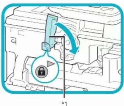
text_image
Diagram showing a mechanical component with a lock icon and directional arrows, labeled with an asterisk symbol.text_image
Diagram of a printer internal structure with labeled parts and directional arrows indicating assembly or movement.natural_image
Line drawing of a hand pressing a button on a printer (no text or symbols)natural_image
Illustration of a printer being inserted into a plastic case, with a hand adjusting the part (no text or symbols visible)natural_image
Illustration showing two hands folding a folded paper with a blue diagonal line (no text or symbols)natural_image
Illustration of a hand inserting a plastic component into a machine (no text or symbols visible)natural_image
Illustration of a hand inserting a plastic into a printer into a plastic case (no text or symbols visible)natural_image
Simple line drawing of a grid layout with a highlighted rectangular cell (no text or symbols)natural_image
Illustration of a printer with a paper clip and magnified view of its cover (no text or symbols)natural_image
Illustration of a printer with an open lid and a blue arrow indicating the open lid (no text or symbols present)text_image
It is very bad enough to be in way, but it's not good. It is good. It is good. It is good. It is good. It is good. It is good. It is good. It is good. It is good. It is good. It is good. It is good. It is good. It is good. It is good. It is good. It is good. It is good. It is good. It is good. It is good. It is good. It is good. It is good. It is good. It is good. It is Where we have been done in the time of the evening for the other.text_image
Diagram of a printer with labeled parts and UI elements, showing front panel layout and internal components.natural_image
Illustration of a printer with an open lid and a blue arrow indicating the process (no text or symbols present)natural_image
Line drawing of a printer connected to a power outlet (no text or symbols)text_image
Diagram showing a printer with ON/OFF switch and directional arrow, likely illustrating a printer operation or status change.natural_image
Illustration of a printer and its screen device (no text or symbols present)
NOTA
text_image
Diagram showing a printer with an ON/OFF switch and its screen, illustrating the process of press or print operation.
IMPORTANTE
natural_image
Pure technical diagram of a mechanical component with no text, numbers, or symbolstext_image
Diagram of a printer with labeled parts including a door panel, printer, and printer unit, showing internal components and connection points.text_image
Technical diagram of an open-plan printer with numbered parts and internal connector labelstext_image
Technical diagram of a printer with numbered parts labeled for identificationtext_image
① ② ③ ④ Cenovo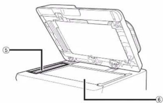
text_image
Technical diagram of a printer or scanner with labeled parts, showing open lid and internal structure.natural_image
Diagram of a device's rear panel with directional arrows indicating movement, no text or symbols presenttext_image
Diagram showing a printer device with labeled parts and directional arrows indicating assembly or process steps.natural_image
Illustration showing two hands folding a folded paper with a blue diagonal line (no text or symbols)text_image
Diagram showing a printer device with labeled parts 1,2 and 3, indicating assembly or installation steps.text_image
Diagram showing a printer with labeled parts and directional arrows indicating assembly or operation.text_image
Diagram showing a printer's internal structure with labeled components and directional arrows indicating movement or assembly.*1: Leva
*2: Guida laterale
text_image
Diagram showing a printer's internal structure with labeled components and directional arrows indicating movement or flow.*1: Leva
*2: Guida anteriore
text_image
Diagram showing a printer device with labeled parts and directional arrows indicating assembly or operation.natural_image
Illustration of a printer next to a computer with a magnified view of the printer's cover (no text or symbols present)
IMPORTANTE
text_image
Diagram showing printer operation with labeled parts and directional arrows indicating process flowtext_image
Diagram illustrating a printer's internal mechanism with lock and pad symbols, showing process flow and component placement.natural_image
Illustration of a printer with a magnified view showing internal components (no text or symbols)natural_image
Diagram of a mechanical component with a curved arrow indicating direction (no text or symbols)natural_image
Illustration of a mechanical component with a rotating arrow indicating rotation (no text or symbols)natural_image
Illustration of a hand holding a plug with a no-smoking symbol (no text or labels)natural_image
Illustration of a printer and a cylindrical device inside a mechanical housing (no text or symbols)
NOTA
text_image
Diagram illustrating a printer's internal mechanism with lock and pad, showing process steps and location indicatorstext_image
Diagram showing a printer with labeled parts and directional arrows indicating process flow or assembly.text_image
Diagram showing printer operation with labeled parts and directional arrows indicating process flowtext_image
Diagram illustrating a printer's internal structure with a magnified view showing the printer's internal components.natural_image
Diagram showing a printer with a blue cover and internal mechanical component, no text or symbols present
ATTENZIONE
natural_image
Technical illustration of a mechanical assembly with a magnified inset showing internal components (no text or symbols)natural_image
Illustration of a hand using a tool to press or install a document with a blue arrow indicating motion (no text or symbols present)
NOTA
natural_image
Cross-sectional diagram of a cable or connector with internal structure (no text or symbols)04
natural_image
Diagram showing a printer with a blue cover and internal mechanical component, no text or symbols present08
natural_image
Illustration of a printer with a magnified view showing internal components (no text or symbols)text_image
Diagram showing a printer with labeled parts and directional arrows indicating process flow or movement.text_image
Diagram showing printer operation with labeled parts and directional arrows indicating process flownatural_image
Illustration of a printer next to a microwave oven, showing the device's internal structure and airflow direction (no text or symbols)natural_image
Illustration of a printer and its internal structure, showing part assembly (no text or symbols)
IMPORTANTE
text_image
Diagram illustrating a printer's internal structure with a magnified view showing the component being inserted into a machine.natural_image
Diagram showing a printer with a blue cover and internal components, no text or symbols present
ATTENZIONE
natural_image
Technical illustration of a mechanical assembly with a magnified inset showing internal components (no text or symbols)text_image
Diagram showing printer operation with magnified view of internal components and a warning symboltext_image
Diagram illustrating a printer's internal mechanism with a magnified view showing the process and directional arrow.*: Contrassegno blu
text_image
Diagram showing a printer device being inserted into a mechanical component, with magnified detail highlighting the insertion process.natural_image
Technical illustration of a mechanical assembly with a blue arrow indicating direction, showing internal components and a box (no text or symbols)
IMPORTANTE
natural_image
Illustration of a hand holding a cylindrical device with a prohibition symbol (no text or labels)natural_image
Diagram of a mechanical device with motion arrows indicating movement, no text or symbols presenttext_image
Diagram illustrating a printer's internal structure and mechanical assembly, with magnified views highlighting the components.text_image
Diagram illustrating a printer's internal mechanism with magnified view showing the device's internal structure and component placement.natural_image
Technical illustration of a mechanical assembly with a magnified inset showing internal components (no text or symbols)
IMPORTANTE
natural_image
Diagram showing a printer with a blue cover and internal components, no text or symbols presentnatural_image
Diagram showing a printer with internal components and a magnified view of a device (no text or symbols present)natural_image
Illustration of a printer and its internal device with a blue arrow indicating the process (no text or symbols present)ATTENZIONE
text_image
Diagram showing a printer with labeled parts and directional arrows indicating process flow or movement.text_image
Diagram showing a printer with labeled parts, including a 2D printer and its open lid.natural_image
Diagram showing a printer device and its internal component, with no visible text or symbolsnatural_image
Technical illustration of a printer holder and internal structure (no text or symbols)
natural_image
Technical illustration of a printer with an arrow pointing to its cover, showing internal components (no text or symbols present)natural_image
Technical line drawing of a printer holder and internal components (no text or symbols)natural_image
Diagram showing a printer device and its internal structure, no text or symbols present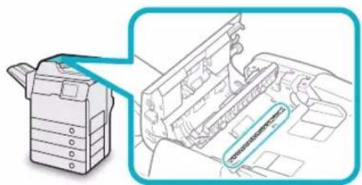
natural_image
Technical illustration of a printer with a magnified inset showing internal components (no text or symbols)natural_image
Illustration of a printer with a blue arrow indicating the open lid (no text or symbols present)natural_image
Illustration of a printer with a magnified view showing internal components (no text or symbols)natural_image
Illustration of a printer being placed on top, showing the blade and handle (no text or symbols)natural_image
Illustration of a printer with a magnified inset showing internal components (no text or symbols)natural_image
Illustration of a printer with a green paper filter being inserted into a stackable device (no text or symbols present)
ATTENZIONE
natural_image
Illustration of a printer with a blue arrow pointing to the open lid (no text or symbols present)
ATTENZIONE
natural_image
Diagram showing a printer device and its internal structure with arrows indicating assembly or transformation (no text or symbols present)
ATTENZIONE
natural_image
Line drawing of a cylindrical mechanical component with threaded ends and a triangular feature on the side (no text or symbols)
AVVERTENZA
natural_image
Technical line drawing of a mechanical component with no visible text or symbolsCartuccia punti ●
| Finisher | Cartuccia punti (Nome/Forma) |
| Staple Finisher-R1 | Canon Staple-P1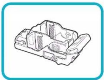 |
text_image
Install Apple Store Store To install the App Store Application, if necessary for your store or store at the same time. Specify: App Store StoreStaple Finisher-R1....73
Copy Card Reader-F1 74
Super G3 FAX Board-AM1 74
CLASS 1 LASER PRODUCT
LASER KLASSE 1
APPAREIL Á LASER DE CLASSE 1
APPARECCHIO LASER DI CLASSE 1
PRODUCTO LÁSER DE CLASE 1
APARELHO A LASER DE CLASSE 1
LUOKAN 1 LASER-TUOTE
LASERPRODUKT KLASS 1
ATTENZIONE
UFST: Copyright © 1989 - 1996, 1997, 2003, 2004, 2008, all rights reserved, by Monotype Imaging Inc.
(b)
Copyright © Unpublished Work of Novell, Inc. All Rights Reserved.
(c)
Portions of this software are copyright © 2007 The FreeType Project(www.freetype.org). All rights reserved.
Software di terzi
text_image
Diagram showing electrical switch installation with labeled components and directional arrows
ATTENZIONE
text_image
Diagram showing a printer with a prohibition symbol and a hand holding a paper, indicating no printing or disassembly.text_image
Diagram showing a printer with a prohibition symbol and a hand inserting paper into the printer's side panel.Staple Finisher-R1
natural_image
Line drawing of a generic electronic device with multiple ports and a central control panel (no text or symbols)Copyright © 2007 -08 Adobe Systems Incorporated. All rights reserved.
Protected by U.S. Patents 5,737,599; 5,781,785; 5,819,301; 5,929,866; 5,943,063; 6,073,148; 6,515,763; 6,639,593; 6,754,382; 7,046,403; 7,213,269; 7,242,415; Patents pending in the U.S. and other countries.
All instances of the name PostScript in the text are references to the PostScript language as defined by Adobe Systems Incorporated unless otherwise stated.
The name PostScript also is used as a product trademark for Adobe Systems' implementation of the PostScript language interpreter.
Except as otherwise stated, any reference to a "PostScript printing device," "PostScript display device," or similar item refers to a printing device, display device or item (respectively) that contains PostScript technology created or licensed by Adobe Systems Incorporated and not to devices or items that purport to be merely compatible with the PostScript language.
Adobe, the Adobe logo, PostScript, the PostScript logo, and PostScript 3 are either registered trademarks or trademarks of Adobe Systems Incorporated in the United States and/or other countries.
Linux is a registered trademark of Linus Torvalds. Microsoft and Windows are either registered trademarks or trademarks of Microsoft Corporation in the United States and/or other countries.
All other trademarks are the property of their respective owners.

text_image
Adobe® PDFCopyright © 2008 Adobe Systems Incorporated. All rights reserved.
Protected by U.S. Patents 6,185,684; 6,205,549; 7,213,269; 7,272,628; 7,278,168; Patents pending in the U.S. and other countries.
All instances of the name PostScript in the text are references to the PostScript language as defined by Adobe Systems Incorporated unless otherwise stated. The name PostScript also is used as a product trademark for Adobe Systems' implementation of the PostScript language interpreter.
Except as otherwise stated, any reference to a "PostScript printing device," "PostScript display device," or similar item refers to a printing device, display device or item (respectively) that contains PostScript technology created or licensed by Adobe Systems Incorporated and not to devices or items that purport to be merely compatible with the PostScript language.
Adobe, the Adobe logo, PostScript, the PostScript Logo, and PostScript 3 are either registered trademarks or trademarks of Adobe Systems Incorporated in the United States and/or other countries.
All other trademarks are the property of their respective owners.
natural_image
Illustration of a printer with two circular insets showing different devices (no text or symbols)natural_image
Illustration of a printer with a magnifying glass, enclosed in a circular frame (no text or symbols)natural_image
Illustration of a printer with a diagonal line, set against a circular background (no text or symbols)natural_image
Illustration of a suitcase with bottles and a bottle emitting smoke, enclosed in a circular frame (no text or symbols)natural_image
Illustration of a printer with a spool, no text or symbols presenttext_image
Diagram showing a thermometer measuring a device, enclosed in a circular prohibition symbol.natural_image
Illustration of a person using a computer device to switch and plug a cable, with no visible text or symbols.natural_image
Illustration of a printer with two stacks of boxes, no text or symbols presentnatural_image
Illustration of a hand holding a pen inside a device, enclosed in a circular frame (no text or symbols)natural_image
Symbolic illustration of a paperclip crossed out by a diagonal line, with no text or symbols present.text_image
Diagram showing electrical switch installation with power plug, switch, and screen, labeled with ON/OFF statesnatural_image
Illustration of a hand pouring liquid from a container into a stack of boxes, enclosed in a circular frame (no text or symbols)natural_image
Illustration of a printer with a magnified view showing its paper roll (no text or symbols present)text_image
Illustration of a generic document layout with text blocks and a placeholder, framed in a blue border.natural_image
Illustration of two electronic devices with heat sinks and ventilation system (no text or symbols)natural_image
Illustration of a printer with open lid and control panel, showing mechanical operation (no text or symbols)natural_image
Diagram of a device panel with buttons and indicators, showing internal components and directional arrows (no text or symbols)natural_image
Illustration of a printer with a paper feed and a blue arrow indicating print direction (no text or symbols)text_image
Safety warning sign with Chinese characters and a prohibition symbol, indicating no hazard or absence of a vehicle.
IMPORTANTE
natural_image
Line drawing of a printer with a green download arrow indicating the paper's edge (no text or symbols present)text_image
Diagram showing a printer with two labeled parts (1 and 2) and directional arrows indicating process flow or rotation.natural_image
Illustration of a printer's door panel with a hand inserting a blue arrow (no text or symbols)text_image
Technical diagram of a printer internal structure with labeled component '1' and directional arrow indicating rotation or movement.natural_image
Diagram of a mechanical device interior showing internal components and a blue arrow indicating direction (no text or symbols)text_image
Technical diagram showing a mechanical device with a magnified inset highlighting a component, labeled with dimension '1'natural_image
Diagram of an internal electrical connector or socket assembly (no text or symbols visible)[Non-Text]
![CANON imageRUNNER ADVANCE 400i - [Non-Text] - 1](/content/2026/04/666717/images/3157039c0477c8cd15f0961425d3ff1bc4c74de074f52b4d409426b0f3a7e754.jpg)
natural_image
Diagram showing three stages of a mechanical device with arrows indicating motion, no text or symbols present.![CANON imageRUNNER ADVANCE 400i - [Non-Text] - 2](/content/2026/04/666717/images/b24b1360e43dbf1b5bd00d5be22c05adf7f6313230991b5450df47443c9f4eff.jpg)
natural_image
Illustration of a hand holding a cylindrical device with a prohibition symbol (no text or labels)natural_image
Diagram of a mechanical device with rotating components and directional arrows indicating motion (no text or symbols)natural_image
Illustration of hands operating a mechanical device with two views of the mechanism (no text or symbols present)text_image
Diagram showing a device's internal components with a magnified view highlighting a component being inserted, labeled with part number *1.natural_image
Diagram of a mechanical device interior showing internal components and a blue arrow indicating direction (no text or symbols)natural_image
Diagram of a printer internal structure with a paper feeding into a printer, showing no text or symbols.natural_image
Illustration of a hand pressing down on a computer control panel with a blue arrow indicating the action (no text or symbols present)natural_image
Simple line drawing of a mechanical component with a blue arrow indicating direction (no text or symbols)natural_image
Diagram of a mechanical component with a rotating arrow indicating rotation (no text or symbols)Retire la tapa protectora.
![CANON imageRUNNER ADVANCE 400i - [Non-Text] - 3](/content/2026/04/666717/images/daac77258e94a5d6415424fbe1a0396c41b7b28ffd24a51dd0b7465ca343e3b1.jpg)
natural_image
Illustration of a hand holding a connector with a no-smoking symbol (no text or labels present)![CANON imageRUNNER ADVANCE 400i - [Non-Text] - 4](/content/2026/04/666717/images/a4c9faaf7fd6f2bff5a88e5f2a932c72020942e08181399ab2552ac0897849ab.jpg)
IMPORTANTE
natural_image
Illustration of a hand inserting a device into a printer case (no text or symbols visible)natural_image
Diagram of a printer internal processing a circular component with a blue arrow indicating motion (no text or symbols present)05
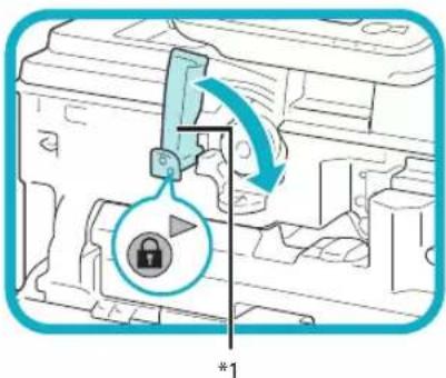
text_image
Diagram showing a lock mechanism with directional arrows and a labeled component, marked with a symbol *1text_image
Diagram of a printer internal structure with labeled parts 1, 2, and directional arrows indicating assembly or movement.natural_image
Line drawing of a hand pressing a button on a computer device (no text or symbols)natural_image
Illustration of a printer being inserted into a plastic case, with a hand pointing to the component (no text or symbols present)natural_image
Illustration showing two hands folding a folded paper with a blue diagonal line (no text or symbols)natural_image
Illustration of a hand placing a blue object into a device into a plastic housing (no text or symbols visible)natural_image
Illustration of a hand inserting a printer into a plastic case (no text or symbols visible)natural_image
Simple line drawing of a grid layout with a highlighted rectangular area (no text or symbols)natural_image
Illustration of a printer with a paper airplane icon and a magnified view of its cover (no text or symbols present)natural_image
Illustration of a printer with an open lid and a blue arrow indicating the open lid (no text or symbols present)text_image
Scanned document page with Chinese text and two embedded images showing hands holding a device, likely illustrating safety or safety guidelines.text_image
Diagram of a printer with labeled parts and UI elements, showing front panel layout and print options.natural_image
Illustration of an open printer with a blue arrow indicating the open lid (no text or symbols present)natural_image
Line drawing of a printer connected to a power outlet (no text or symbols)natural_image
Illustration of a printer with a scroll and a screen, connected to a handheld device (no text or symbols present)
NOTA
text_image
Diagram showing a printer with an ON/OFF switch and a screen, illustrating the process of switching from a printer to an open screen.
IMPORTANTE
natural_image
Pure technical diagram of a mechanical component with no text, numbers, or symbolstext_image
Diagram of a printer with labeled parts including a door panel, printer, and printer unit, showing internal components and connection points.text_image
Technical diagram of a printer with numbered parts and internal connector labelstext_image
Technical diagram of an open printer with numbered parts labeled for identificationtext_image
① ② ③ ④ Cane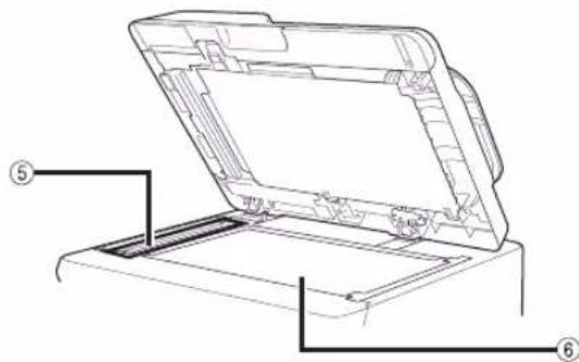
text_image
Technical diagram of a printer with labeled parts, showing open lid and internal structuretext_image
500i ① ② ③ ④ ⑤ ⑥ ⑦ ⑧ ⑨ ⑩ ⑪ ⑫ ⑬ ⑭ ⑮ ⑯ ⑰ ⑱ ⑲ ⑳ ㉑ ㉒ ㉓ ㉔ ㉕ ㉖ ㉗ ㉘ ㉙ ㉚ ㉛ ㉜ ㉝ ㉞ ㉟ ㉳ ㉟ ㉟a ㉟b ㉟c ㉟d ㉟e ㉟f ㉟g ㉟h ㉟i ㉟j ㉟k ㉟l ㉟m ㉟n ㉟o ㉟p ㉟q ㉟r ㉟s ㉟t ㉟u ㉟v ㉟w ㉟x ㉟y ㉟z ㉟ac ㉟ac1a1a1a1a1a1a1a1a1a1a1a1a1a1a1a1a1a1a1a1a1a1a1a1a1a1a1a1a1a1a1a1a1a1a1a1a1a1a1a1a1a1a1a1a1a1a1a1a1a1a1b1b2b3b4b5b6b7b8b9b10b11b12b13b14b15b16b17b18b191 [Menú principal]
natural_image
Diagram of a device with a curved arrow indicating rotation or movement, showing no text or symbols present.*1: Rango ajustable
![CANON imageRUNNER ADVANCE 400i - [Menú principal] - 1](/content/2026/04/666717/images/2e5a54be9fc6472f80a2833c2ee9afe5035e92cf35a7c1110a2a48facebf27bf.jpg)
IMPORTANTE
text_image
Diagram showing a printer device with labeled parts and directional arrows indicating assembly or connection.natural_image
Illustration showing two hands folding a folded paper with a blue diagonal line (no text or symbols)text_image
Diagram showing printer internal structure with labeled parts 1,2 and 3, likely illustrating a printer or printer assembly.text_image
Diagram showing a printer device with labeled parts and directional arrows indicating assembly or operation.text_image
Diagram illustrating a printer's internal structure with labeled components and directional arrows indicating assembly or movement.*1: Palanca
*2: Guía lateral
text_image
Diagram showing a printer's internal structure with labeled components, including a zoomed-in view of the component.*1: Palanca
*2: Guía frontal
text_image
Diagram showing a printer with labeled parts and an arrow indicating assembly or transformation, including numbers 1,2 and 3.natural_image
Illustration of a printer with a magnified view of its cover (no text or symbols present)
IMPORTANTE
text_image
Diagram showing a printer with two labeled parts, illustrating the process of file transfer or storage.text_image
Diagram illustrating a printer's internal structure and lock mechanism, showing paper feeding into a device with an open lock icon.natural_image
Illustration of a printer with a magnified view showing internal components (no text or symbols)natural_image
Diagram of a mechanical component with a blue arrow indicating direction (no text or symbols)natural_image
Diagram of a mechanical component with a rotating arrow indicating rotation (no text or symbols)natural_image
Illustration of a hand holding a plug with a no-smoking symbol (no text or labels)natural_image
Illustration of a printer and a cylindrical device inside a mechanical housing (no text or symbols)
NOTA
text_image
Diagram illustrating a printer's internal mechanism with lock and padlock operation, showing process steps and component placement.text_image
Diagram showing a printer with labeled parts and directional arrows indicating process flow or assembly.text_image
Diagram showing printer image processing steps with numbered arrows indicating process flowtext_image
Diagram illustrating a printer's internal structure with a magnified view showing a mechanical component and directional arrow.natural_image
Diagram showing a printer with a blue ribbon interacting with a mechanical component inside a machine (no text or symbols present)
ATENCIÓN
natural_image
Technical illustration of a mechanical assembly with a magnified inset showing internal components (no text or symbols)natural_image
Illustration of a hand holding a device with a paper sheet and a blue arrow indicating motion (no text or symbols)
NOTA
natural_image
Diagram of a cable or connector with internal structure, no text or symbols presentnatural_image
Diagram showing a printer with a blue cover and internal structure, no text or symbols presenttext_image
Diagram showing a printer with a magnified view of internal components, likely illustrating a mechanical or electronic assembly process.text_image
Diagram showing a printer with labeled parts and directional arrows indicating process flowtext_image
Diagram showing a printer with two labeled parts (1 and 2) indicating internal components or functions.natural_image
Illustration of a printer next to a door with a close-up view of its lid (no text or symbols present)natural_image
Illustration of a printer with a blue arrow pointing to a mechanical component (no text or symbols present)
IMPORTANTE
text_image
Diagram illustrating a printer's internal structure and mechanical component, with an arrow indicating rotation direction.natural_image
Diagram showing a printer with a blue arrow pointing to a mechanical component inside a machine (no text or symbols present)
ATENCIÓN
natural_image
Technical illustration of a mechanical assembly with a magnified inset showing internal components (no text or symbols)text_image
Diagram illustrating printer operation with magnified view of internal components and a close-up of the printer's internal structure.text_image
Diagram illustrating a printer's internal structure with a magnified view showing the printer's internal components and directional arrows.*: Marca azul
text_image
Diagram illustrating a printer's internal structure and tool path, showing hand positioning and tool insertion.natural_image
Technical illustration of a mechanical assembly with a blue arrow indicating direction (no text or symbols present)
IMPORTANTE
natural_image
Illustration of a hand holding a cylindrical device with a prohibition symbol (no text or labels)natural_image
Diagram of a mechanical device with motion arrows indicating movement, no text or symbols present10
text_image
Diagram illustrating a printer's internal structure and mechanical assembly, with magnified views highlighting the components.text_image
Diagram showing a printer with a magnified view of the internal components, likely illustrating a mechanical or electrical assembly process.natural_image
Technical illustration of a mechanical assembly with a magnified inset showing internal components (no text or symbols)
IMPORTANTE
natural_image
Illustration of a printer with a highlighted internal component, showing no text or symbols.text_image
Diagram showing a printer with internal components and a magnified view of a device with a handle, likely illustrating a printer mechanism or assembly.natural_image
Illustration of a printer and its internal device with a blue arrow indicating a process (no text or symbols present)
ATENCIÓN
text_image
Diagram showing a printer with labeled parts and directional arrows indicating process flow or movement.text_image
Diagram showing a printer with labeled parts, including a 2D view and an open device with two labeled sections.natural_image
Diagram showing a printer device and its internal component, with no visible text or symbolsnatural_image
Technical line drawing of a printer holder and internal components (no text or symbols)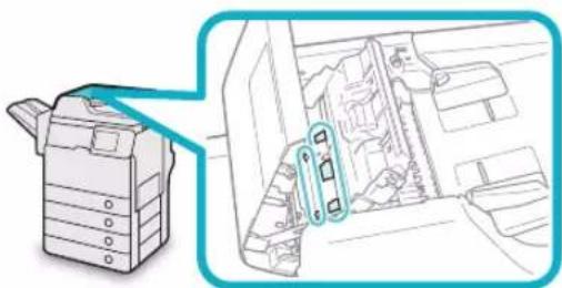
natural_image
Diagram showing a printer device and its internal components, no text or symbols presentnatural_image
Technical line drawing of a printer holder and internal components (no text or symbols)natural_image
Diagram showing a printer device and its internal component with a magnified view of the interior (no text or symbols)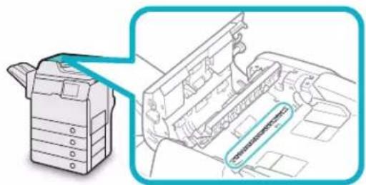
natural_image
Technical line drawing of a printer with a magnified view showing internal components (no text or symbols)natural_image
Illustration of a printer with an open lid and a blue arrow indicating the process (no text or symbols present)natural_image
Illustration of a printer with a magnified view showing internal components (no text or symbols)text_image
Diagram illustrating a printer's printing process with magnified view showing the printer's edge being cut.natural_image
Illustration of a printer with a magnified view showing internal components (no text or symbols)natural_image
Illustration of a printer with a blue arrow indicating the open lid area (no text or symbols present)
ATENCIÓN
natural_image
Illustration of a printer with an open lid and a magnified view showing the lid being folded (no text or symbols present)
ATENCIÓN
natural_image
Diagram showing a printer device being inserted into a mechanical component, with no visible text or symbols.
ATENCIÓN
natural_image
Line drawing of a cylindrical mechanical component with internal grooves and a triangular feature (no text or symbols)
ADVERTENCIA
natural_image
Technical line drawing of a mechanical component with no visible text or symbolsCartucho de grapas ●
text_image
To create the codebook application, a version by using a related to the codebook. It is also displayed in the main image.Pantalla Menú principal ●
CLASS 1 LASER PRODUCT
LASER KLASSE 1
APPAREIL Á LASER DE CLASSE 1
APPARECCHIO LASER DI CLASSE 1
PRODUCTO LÁSER DE CLASE 1
APARELHO A LASER DE CLASSE 1
LUOKAN 1 LASER-TUOTE
LASERPRODUKT KLASS 1

ATENCIÓN
UFST: Copyright © 1989 - 1996, 1997, 2003, 2004, 2008, all rights reserved, by Monotype Imaging Inc.
(b)
Copyright © Unpublished Work of Novell, Inc. All Rights Reserved.
(c)
Portions of this software are copyright © 2007 The FreeType Project (www.freetype.org). All rights reserved.
text_image
Diagram showing electrical connection with a plug, switch, and screen, labeled in Chinese.
ATENCIÓN
text_image
Diagram showing a printer with a prohibition symbol overlay and a hand holding a tray, indicating no protection or disapproval.text_image
Diagram showing a printer with a prohibition symbol and a hand holding a paper, indicating no printing or anti-printing.30-2, Shimomaruko 3-chome, Ohta-ku, Tokyo 146-8501, Japan
CANON U.S.A., INC.
One Canon Park, Melville, NY 11747, U.S.A.
CANON CANADA INC.
6390 Dixie Road Mississauga, Ontario L5T 1P7, Canada
CANON EUROPA N.V.
Bovenkerkerweg 59, 1185 XB Amstelveen, The Netherlands
(See http://www.canon-europe.com/ for details on your regional dealer)
CANON LATIN AMERICA, INC.
703 Waterford Way Suite 400 Miami, Florida 33126 U.S.A.
CANON AUSTRALIA PTY. LTD
1 Thomas Holt Drive, North Ryde, Sydney, N.S.W. 2113, Australia
CANON CHINA CO., LTD
15F Jinbao Building No.89 Jinbao Street, Dongcheng District, Beijing 100005, China
CANON SINGAPORE PTE. LTD.
1 HarbourFront Avenue #04-01 Keppel Bay Tower, Singapore 098632
CANON HONGKONG CO., LTD
19/F., The Metropolis Tower, 10 Metropolis Drive, Hunghom, Kowloon, Hong Kong