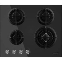
CG4HN/B - Cooker TAURUS - Free user manual and instructions
Find the device manual for free CG4HN/B TAURUS in PDF.


| Brand | Taurus |
| Model | CG4HN/B |
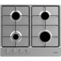
| Product type | Built-in gas hob |
| Dimensions (W x D x H) | 600 x 515 x 90 mm |
| Power supply | 220-240 V ~ 50-60 Hz, 2 W |
| Gas supply | LPG (G30 29 mbar) or Natural gas (G20 20 mbar) |
| Number of burners | 4 |
| Burner types | 1 wok, 2 semi-rapid, 1 auxiliary |
| Total power | 7.8 kW |
| Ignition | Continuous automatic ignition |
| Safety device | Automatic gas shut-off if flame goes out |
| Surface material | Glass |
| Gas connection | Thread G 1/2 |
| Energy efficiency | 58.44% (G20) / 58.26% (G30) |
| Included accessories | 4 supports, 4 sponges, 4 screws, 4 injectors, 1 gas elbow, 1 manual |
| Warranty | In accordance with current legislation |
| After-sales service | Authorized by Taurus |
| Appliance class | Class 3 (EN 30-1-1) |
Frequently Asked Questions - CG4HN/B TAURUS
User questions about CG4HN/B TAURUS
0 question about this device. Answer the ones you know or ask your own.
Ask a new question about this device
Download the instructions for your Cooker in PDF format for free! Find your manual CG4HN/B - TAURUS and take your electronic device back in hand. On this page are published all the documents necessary for the use of your device. CG4HN/B by TAURUS.
USER MANUAL CG4HN/B TAURUS
natural_image
Line drawing of a gas stove with three fans and four control knobs (no text or symbols)Español
CG4HN/B
Estimado cliente,

natural_image
Four circular mechanical components with crosshairs, arranged in a 2x2 grid and four below, with three circles below (no text or symbols)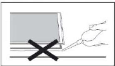
natural_image
Simple line drawing of a laptop with a hand holding a pen and a black X mark, no text or symbols present.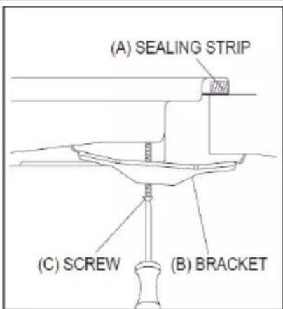
Gas supply replacement and installation guidelines:
natural_image
Simple line drawing of a curved line with a circle, an asterisk, and a dot (no text or symbols)natural_image
Four identical diagrams showing curved lines with circles and asterisks, no text or symbols presentMany thanks for choosing to purchase a Taurus brand product.
Thanks to its technology, design and operation and the fact that it exceeds the strictest quality standards, a fully satisfactory use and long product life can be assured.
SAFETY ADVICE AND WARNINGS:
- Read the appliance instructions before installing and using. Keep these instructions in a place where you can find them easily. Failure to follow and observe these instructions could lead to an accident.
- The images shown in these instructions are for guidance only.
- The manufacturer shall not be responsibility for any damages to persons or properly if the requirements of this manual are not complied, caused by incorrect installation or use of the appliance.
- The appliance has not been certified for use in countries other than those marked on appliance.
This appliance shall be installed in accordance with regulations in force and only used in a well-ventilated area.
- This appliance must only be used in well ventilated places. It must not be connected to a combustion product removal device.
- All operations relating to installation, connection, regulation and conversion to other gas types must be carried out by an authorised installation engineer, respecting all applicable regulations, standards and the specifications of the local gas and electricity suppliers. Special attention shall be paid to ventilation regulations.
- This appliance is for household use only, not professional, industrial use.
- This appliance cannot be installed on yachts or in caravans.
Prior to installation, ensure that the gas and electrical supply complies with the type stated on the rating plate. Is recommended contact with the Technical Assistance Service to change to another gas type.
- This appliance should be installed by a qualified technician or installer.
- This appliance is class 3 type, according to EN 30-1-1 standard for gas appliance, built-in appliance.
- Any misuse or failure to follow the instructions for use renders the guarantee and the manufacturer's liability null and void.
SAFETY INSTRUCTIONS:
- Do not use the appliance in association with a programmer, timer or other device that automatically switches it on.
- This appliance shall not be used by children.
- This appliance can be used by people with reduced physical, sensory or mental capabilities or lack of experience and knowledge if they have been given supervision or instruction concerning use of the appliance in a safe way and understand the hazards involved.
- This appliance is not a toy. Children should be supervised to ensure that they do not play with the appliance.
- Cleaning and user maintenance must not be done by children.
Do not allow children to play near or with the appliance. The appliance gets hot when it is in use. Children should be kept away until it has cooled.
- Children can also injure themselves by pulling pans or pots off the appliance.
- Only use appliance to prepare food.
- Do not use this appliance if it comes in contact with water.
- Do not operate the appliance with wet hands.
- The heating and cooking surface of the appliance become hot when they are in use, take all due protections.
Do not use large clothes, tea towels or similar as the ends could touch the flames and catch fire.
- Never leave the appliance unattended when cooking.
- Unstable or misshapen pans should not be used on the appliance as they can cause an accident by tipping or spillage.
- Do not use or store flammable materials in the storage drawer near this appliance.
- Perishable food, plastic items and aerosols may be affected by heat and should not store above or below the appliance.
- Do not spray aerosols in the vicinity of this appliance while it is in operation.
- Ensure the controls knobs are in the OFF "simbolo" position when not in use.
- Never use abrasive or caustic agents.
- This appliance should only be repaired or serviced by an authorized Service Agent and only genuine approved spare parts should be used.
- Before attempting to clean the appliance, it should be cooled.
- Steam jet or any other high-pressure cleaner should not be used to clean the appliance.
- Always turn burner controls OFF before removing cookware.
- Use heat-resistant pot holders or gloves when handling hot pots and pans.
- Do not let pot holders come near open flames when lifting cookware.
- Take care not to let pot holders or gloves get damp or wet, as this causes heat to transfer through the material quicker with the risk of burning yourself.
- Only ever use the burners after placing pots and pans on them. Do not heat up any empty pots or pans.
- Never use plastic or aluminium foil dishes on the appliance.
- When using other electrical appliances, ensure the cable does not come into contact with the appliance surfaces of the cooking appliance.
- To minimize the possibility of burns, ignition of flammable materials and spillage, turn cookware handles toward the side or centre of the top plate without exceeding over adjacent burners.
- Carefully watch foods being fried at a high flame setting.
· Always heat fat slowly and watch s its heats.
- Foods for frying should be as dry as possible. Frost on frozen foods or moisture on fresh foods can cause hot fat to bubble up and over the sides of the pan.
Never try to move a pan of hot fat, especially a deep fat fryer. Wait until the fat is completely cool.
When using glass cookware, make sure it is designed for top plate cooking. If the surface of glass is cracked, switch-off the appliance to avoid defeat electrocution.
WARNINGS:
- Do not modify this appliance.
Prior to installation, ensure that the local distribution conditions (nature of the gas and gas pressure) and the adjustment of the appliance are compatible.
☐ This product is not connected to a combustion products evacuation device. It should be installed and connected in accordance with current installation regulations. Particular attention should be given to the relevant requirements regarding ventilation.
Before installing, turn OFF the gas and electricity supply to the appliance.
Gas pipe or connector shouldn't be bent or blocked by any other appliances.
☐ Check the dimensions of the appliance as well as the dimensions of the gap to be cut in the kitchen unit.
☐ The panels located above the work surface, directly next to the appliance, must be made of non-flammable material. Both the stratified surfacing and the glue used to secure it should be heat resistant, to prevent deterioration.
Turn on appliance tap and light each burner. Check for a clear blue flame without yellow tipping. If burners show any abnormalities check the following:
- Burner lid on correctly
- Flame spreader positioned correctly
- Burner vertically aligned with injector nipple
☐ A full operational test and test for possible leakages must be carried out by the fitter after installation.
☐ The flexible hoses shall be fitted in such a way that it cannot come into contact with a moveable part of the housing unit and does not pass through any space susceptible of becoming congested.
☐ Do not turn on the light.
☐ Do not switch on/off any electrical appliance and do not touch any electric plug.
☐ Do not use a telephone.
☐ Stop using the product and close the middle valve.
☐ Open the window to ventilate.
☐ Contact with service centre by using a phone outside.
INSTALLATION:
☐ Remove all packaging before using the appliance.
☐ After unpacking the appliance, make sure that product is not damaged and that the connection cord is in perfect condition. Otherwise, contact the dealer before installing the appliance.
☐ The adjacent furniture and all materials used in the installation must be able to withstand a minimum temperature of 85^ C above the ambient temperature of the room it is located in, whilst in use.
☐ The gas pipe and electrical cable must be installed in such way that they do not touch any parts or the appliance.
☐ The adjustment conditions for this appliance are stated on the label.
☐ The use of a gas cooking appliance results in a production of heat and moisture in the room in which it is installed. Ensure that the kitchen is well ventilated: keep natural ventilation holes open or install a mechanical ventilation device (extractor hood).
☐ Prolonged intensive use of the appliance may call for additional ventilation, for example opening of a window, or more effective ventilation, for example increasing the level of mechanical ventilation where present.
- The place in which the appliance is installed must be stable and properly secured.
- Place. used to fix the appliance must be made of non-flammable and heat resistant materials.
- The appliance cannot be installed above fridges, washing machines, dishwashers and similar.
- The hob may only be fitted above a ventilated oven.
If an oven is installed underneath the hob, the thickness specified for the work surface may exceed the minimum thickness stated in these instructions. Check the information in the oven installation instructions.
If an extractor is installed, you must follow the instructions in the installation manual, always respecting the minimum vertical distance from the hob (700mm)
- Ensure that appliance is connected to the earth when make the electrical installation.
HOW TO PLACE THE APPLIANCE:
The kitchen or countertop unit in which the appliance is to be integrated shall have the following minimum distances:
- The edges of the hob must be a minimum distance of 60 mm from a side or rear wall.
- 700 mm between the highest point of the hob surface (including the burners) and the underside of any horizontal surface directly above it.
- 400 mm between the hob surfaces, providing that the underside of the horizontal surface is in line with the outer edge of the hob. If the underside of the horizontal surface is lower than 400 mm, then it must be at least 50 mm away from the outer edges of the hob.
- 50 mm clearance around appliance and between the hob surface and any combustible materials.
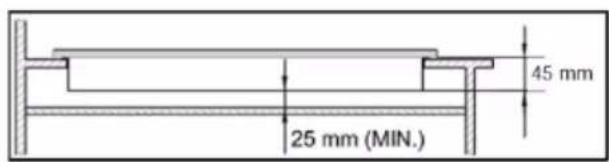
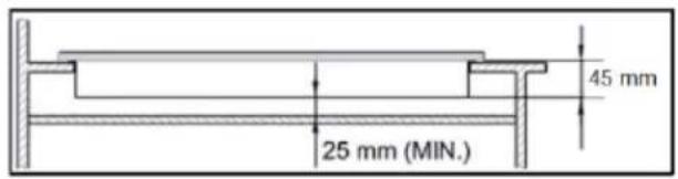
- You must have a gap of at least 25mm and at most 74 mm between the underneath of the appliance and any surface that is below it.
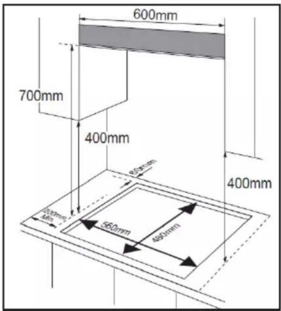

- The cut-out size must obey the indication.
INSTALLING PROCESS:
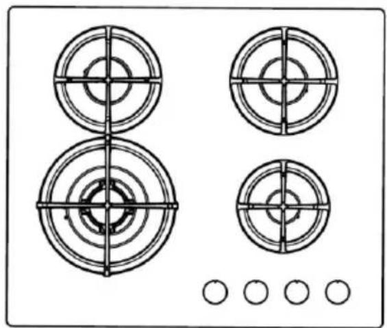
natural_image
Four circular target-like diagrams with crosshairs, arranged in a 2x2 grid and a row of five empty circles below (no text or symbols)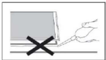
natural_image
Simple line drawing of a laptop with a hand holding a pen and a black X mark, no text or symbols present.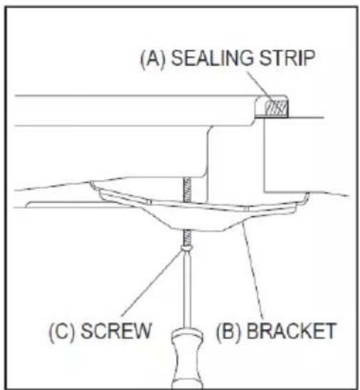
- Remove the pan supports, the burner lid and flame spreader and carefully turn the appliance upside down and place it on a cushioned mat.
• Take care that the ignition devices and flame supervision devices are not damaged in this operation.
- Apply the sponge provided around the edge of the appliance. The thickness of the sponge is 3 mm and the width is 10 mm.
- Do not leave a gap in the sealing agent or overlap the thickness.
- Do not use a silicone sealant to seal the appliance against the aperture. This will ae it difficult to remove from the aperture in future, particularly if needs to be serviced.
- Place the bracket (B) over the holes that match the size of the screw. There are one set of screws holes in each corner of the hob. Slightly tighten a screw (C) through the bracket (B) so that the bracket is attached to the hob, but so that you can still adjust the position.
- Carefully turn the hob back over and then gently lower it into the aperture hole that you have cut out.
- On the underneath of the hob, adjust the brackets into a position that is suitable for your worktop. Then fully tighten the screws (C) to secure the hob into position.
GAS CONNECTION:
- This appliance must be installed and connected in accordance with installation regulations in force in the country in which the appliance is to be used.
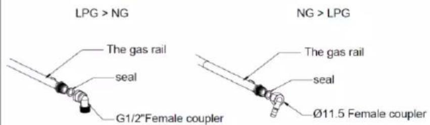
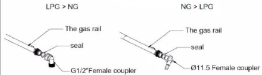
- This appliance is supplied to run on LPG and natural gas. Conversion for use on LPG and natural gas must only be undertaken by a qualified person.
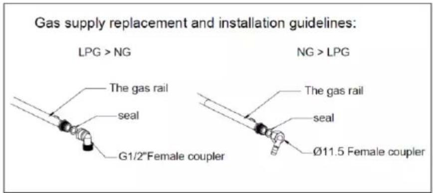
- It is the law that all gas appliances are installed by competent persons in accordance with the current edition of Gas Safety Installation and Use Regulations.
- It is in your interest and that of safety to ensure compliance with the law.
GAS SPECIFICATION
| GAS TYPE AND PRESSURE | HEAT INPUT AND ORIFICE SIZE MARKED (MM) | |||
| Wok burner | Rapid burner | Semi-rapid | Auxiliary - rapid | |
| 3,3kW(241g/h) | / | 1,75 kW(127 g/h) | 1,0 kW(73 g/h) | |
| G30 29 mbar | 0,93 | / | 0,66 | 0,50 |
| G20 20 mbar | 1,28 | / | 1,00 | 0,78 |
ELECTRICAL CONNECTION:
- This appliance must be earthed.
- This appliance is designed to be connected to a 220-240 V, 50-60 Hz electricity supply.
-
The wires in the mains lead are coloured in accordance with the following code:
-
Green/yellow → Earth
- Blue → Neutral
- Brown → Live
- The wire which is coloured green and yellow must be connected to the terminal which is marked with the letter E or by the earth symbol.
WIRING DIAGRAM
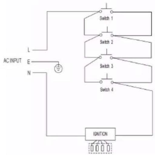
flowchart
graph TD
    A["AC INPUT"] --> B["L"]
    A --> C["E"]
    A --> D["N"]
    B --> E["Switch 1"]
    C --> F["Switch 2"]
    D --> G["Switch 3"]
    E --> H["Switch 4"]
    F --> H
    G --> H
    H --> I["IGNITION"]
    I --> J["Output"]
    style A fill:#f9f,stroke:#333
    style I fill:#ccf,stroke:#333
- When the power cord is damaged it must be replaced by the manufacturer to produce, customer service agent or similarly qualified personnel.
GAS ADJUSTMENT:
- Take precautions on the operations and adjustments to be carried out when converting from one gas to another.
- All work must be carried out by a qualified technician.
- Before you begin, turn off the gas and electricity supply to the appliance.
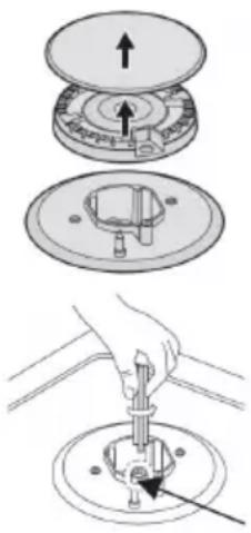
1. Change the injector of the burners
Remove the pan support, burner lid and flame spreader.
Unscrew the injector using a 7mm box spanner and replace it with the stipulated injector for new gas supply. Carefully reassemble all the components.
After injectors are replaced, it is advisable to strongly tighten the injector in place.
Injector
2. Adjustment of minimum level of the flame
- Turn the taps down to minimum.
- Remove the knob from the tap and place a small bladed screwdriver in the centre of the tap shaft.
- The correct adjustment is obtained when the flame has a length of about 3-4 mm.
- For butane / propane gas, the adjusting screw must be tightly screwed in.
- Refit the control knob.
Make sure that the flame does not go out by quickly turning from maximum flow to minimum flow. If it does then remove the control knob and make further adjustments to the gas flow, testing it again once the adjustment has been made.
- Repeat this process for each one of the gas taps.
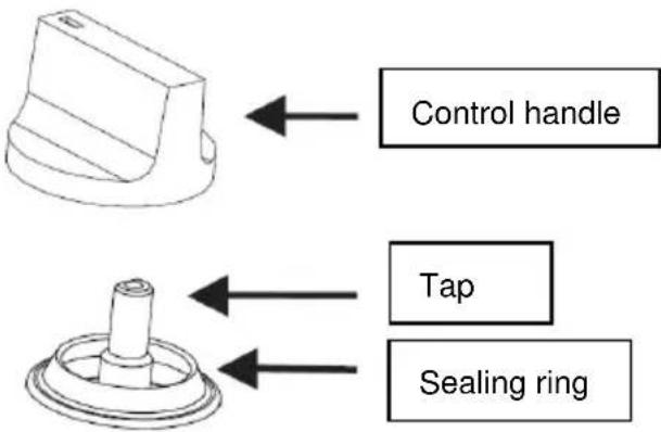
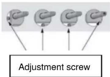
- Do not dismantle the tap shafe: in the event of malfunction, change the whole tap.
Before placing the burners back on the top place, make sure that the injector is not blocked. - A full operational test and a test for possible leakages must be carried out after gas conversion (such as soap water or gas detector).
After completing conversion, a qualified technician or installer has to mark "V" on the right gas category to match with the setting in rating plate. Remove the previous "V" mark.
DESCRIPTION
| Top Plate | Dimension (WxDxH) | Ignition device | Gas connection | Electricity Supply | Burner Feature | ΣQn |
| Glass | 600x515x90mm | Continuous Ignition Type | G 1/2 thread | 220-240 Vac 50-60 Hz 2W | Wok burner (1) Semi-rapid (2) Auxiliary (1) | 7,8 kW |
Accessories
1 Bracket (4)
2 Sponge (4)
3 Screw (4)
4 Injector (4)
5 Gas-pipe bend (1)
6 Instructions manual (1)
If the model of your appliance does not have the accessories described above, they can also be bought separately from the Technical Assistance Service.
INSTRUCTIONS FOR USE
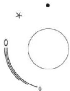
- The following symbols will appear ion the control panel, next to each control handle:
natural_image
Simple line drawing of a curved object and a circle with a star symbol (no text or labels)
Black circle: gas OFF.

Large flame: maximum setting.

Small flame: minimum setting.
- The minimum setting is at the end of the anti-clockwise rotation of the control handle.
- All operation positions must be selected between the maximum and minimum position.
- The symbol on the control panel, next to the control handle will indicate which burner it operates.
AUTOMATIC IGNITION WITH FLAME FAILURE SAFETY DEVICE
The appliance is fitted with a flame failure safety device on each burner, which is designed to stop the flow of gas to the burner head in the event of the flame going out.
TO IGNITE A BURNER
natural_image
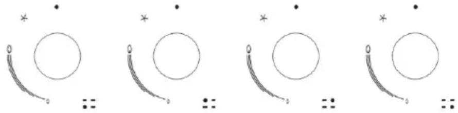
Four identical diagrams showing circles with curved lines and asterisks above, arranged horizontally (no text or symbols)- Press in the control knob of the burner that you wish to light and turn it anti-clockwise to the maximum position.
- If you keep the control knob depressed, the automatic ignition for the burner will operate.
- You should hold down the control knob for 15 seconds after the flame on the burner has not lit, stop operating the device and open the compartment door and/or wait at least 1 minute before attempting a further ignition of the burner.
After this 15 second interval, to regulate the flame you should continue turning the control knob anti-clockwise until the flame is at a suitable level. The operating position MUST be at a position between the maximum and minimum position. - To switch the burner OFF, turn the control knob fully clockwise to the gas OFF position.
- In case of power failure, the burners can be lit by carefully using a match.
SAFETY AND ENERGY SAVING DEVICE
It is recommended to use roasting pans, frying pans or grill stones heated simultaneously on several burners because the resulting heat build-up may damage the appliance.
- Do not touch the top plate and trivet whilst in use for a certain period after use.
As soon as a liquid starts boiling, turn down the flame so that it will barely keep the liquid simmering.
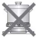
- The diameter of the bottom of the pan should correspond to that of the burner.
- Do not use cookware that overlaps the edge of the burner.
| BURNERS | PANS | |
| min | Max | |
| Triple-Crown | 200 mm | 240 mm |
| Rapid | 200 mm | 240 mm |
| Semi-Rapid | 160 mm | 180 mm |
| Auxiliary | 120 mm | 160 mm |
| NO | YES | ||
 | Do not use small diameter cookware on large burners. The flame should never come up the sides of the cookware. | Always use cookware that is suitable for each burner, to avoid wasting gas and discolouring the cookware. |  |
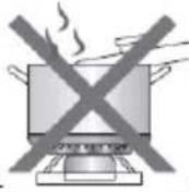 | Avoid cooking without a lid or with the lid half off, this waste energy. | Place a lid on the cookware. | 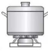 |
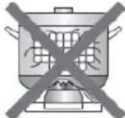 | Do not use a pan with a convex or concave bottom. | Only use pots, saucepans and frying pans with a thick, flat bottom. | 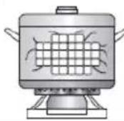 |
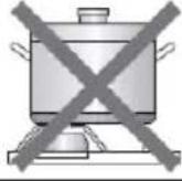 | Do not place cookware on one side of a burner, as it could tip over. | Always place the cookware right over the burners, not to one side. | 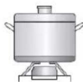 |
| Do not use the cookware with a large diameter on the burners near the controls, which when placed on the middle of the burner may touch the controls or be so close to them that they increase the temperature in this area and may cause damage. | |||
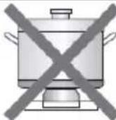 | Never place cookware directly on top of the burner. | Place the cookware on top of the trivet. | |
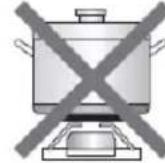 | Do not place anything, e.g. Flame tamer, asbestos material between pan a pan support as serious damage to the appliance may result. | ||
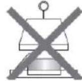 | Do not use excessive weight and do not hit the cooktop with heavy objects. | Handle cookware carefully when they are on the burner. | 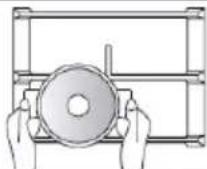 |
- Cleaning operations must only be carried out when the appliance is completely cool.
- The appliance should be disconnected from your mains supply before commencing any cleaning process.
- Clean the appliance regularly, preferably after each use.
- Abrasive cleaners or sharp objects will damage the appliance surface; you should clean it using water and a little washing up liquid.
| Usable | Unusable | ||||
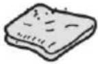 | Soft cloth | 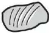 | Nylon brush |  | Metal brush |
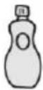 | Neutral detergent | 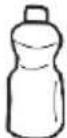 | Edible oil | 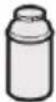 | Acidic/Alkali detergent |
 | Abrasive |  | Thinner/Benzene | ||
PAN SUPPORT, CONTROL HANDLES
Take off the pan support.
- Clean these and the control handles with a damp cloth, washing up liquid and warm water. >For stubborn soiling, soak beforehand.
- Dry everything with a clean soft cloth.
TOP PLATE
Regularly wipe over the top plate using a soft cloth well wrung-out in warm water to which a little washing up liquid has been added.
- Dry the top plate thoroughly after cleaning.
- Thoroughly remove salty foods or liquids from the hob as soon as possible to avoid the risk of corrosion.
- Stainless steel parts of the appliance may become discoloured over time. This is normal because of the high temperatures. Each time the appliance is used these parts should be cleaned with a product that is suitable for stainless steel.
BURNERS
- Remove the burners lids and Flame Spreaders by pulling them upwards and away from the top plate.
- Soak them in hot water and a little detergent or washing up liquid.
- After cleaning and washing them, wipe and dry them carefully. Make sure that the flame holes are clean and completely dry.
- Wipe and fixes parts of the burner cup with a damp cloth and dry afterwards.
Gently wipe the ignition device and flame supervision device with a well wring-out cloth and wipe dry with a clean cloth.
Before placing the burners back on the top plate, make sure that the injector is not blocked.
Re-assemble the auxiliary, Semi-Rapid, Rapid and Triple-Crown burners as follows:
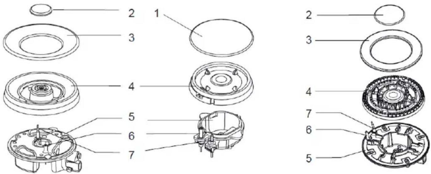
- Place the flame spreader (4) on to the burner cup (5) so that the ignition device and the flame supervision device extend through their respective holes in the flame spreader. The flame spreader must click into place correctly.
Position the burner lid (1, 2, 3) onto the flame spreader (4) so that the retaining pins ft into their respective receded. - Replace parts in the correct order after cleaning.
· DO not mix up the top and bottom. - The locating pins must fit exactly into the notches.
FOR EU PRODUCT VERSIONS AND/OR IN CASE THAT IT IS REQUESTED IN YOUR COUNTRY:
ECOLOGY AND RECYCLABILITY OF THE PRODUCT
The materials of which the packaging of this appliance consists are included in a collection, classification and recycling system. Should you wish to dispose of them, use the appropriate public recycling bins for each type of material.
- The product does not contain concentrations of substances that could be considered harmful to the environment.
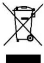
- This symbol means that in case you wish to dispose of the product once its working life has ended, take it to an authorised waste agent for the selective collection of Waste from Electric and Electronic Equipment (WEEE).
ANOMALIES AND REPAIR
Take the appliance to an authorised technical support service if product is damaged or other problems arise. Do not attempt to disassemble or repair the appliance yourself as this may be dangerous.
TROBLESHOOTING:
- Some minor problems can be resolved as follows:
| Problem | Probable cause | Solution |
| Not Ignited. | No spark. | Check the electricity supply. |
| The burner lid is badly assembled. | Assemble the lid correctly. | |
| The gas supply is closed. | Open the gas supply completely. | |
| Badly ignited. | The gas supply is not completely open. | Open the gas supply completely. |
| The burner lid is badly assembled. | Assemble the lid correctly. | |
| The ignition plug is contaminated with alien substance. | Wipe alien substance with a dry cloth. | |
| The burners are wet. | Dry the burners lid carefully. | |
| The holes in the flame spreader are clogged. | Clean the flame spreader. | |
| Noise made when combusted and ignited. | The burner lid is bad assembly. | Assemble the burner lid correctly. |
| Flame goes out when in use. | The flame supervision device is contaminated with alien substance. | Clean the flame supervision device. |
| Product being cooked has boiled over and extinguished the flame. | Turn off burner knob. Wait one minute and reignite zone. | |
| A strong draught may have blown the flame out. | Please turn off zone and check cooking are for draught such as open windows. Wait one minute and reignite zone. | |
| Yellow flame. | The holes in the flame spreader are clogged. | Clean the flame spreader. |
| Different gas is used. | Check the gas used. | |
| Unstable flame. | The burner lid is badly assembled. | Assemble the burner lid correctly. |
| Gas smell. | Gas leakage. | Stop using the product and close middle valve. Open the window to ventilate. Contact our service center by using a phone outside. |
If problem is not solved, please contact customer care center.
The following information is regarding to energy labelling and ecodesign:
| Product fiche | ||||||
| Model: | CG4HN/B | |||||
| Type of hob: | Gas | |||||
| Number of cooking zones and/or areas: | 4 | |||||
| Energy efficiency per gas burner (EEgas burner) | G20 | G30 | ||||
| Wok Burner | Semi-rapid 1 Burner | Semi-rapid 2 Burner | Wok Burner | Semi-rapid 1 Burner | Semi-rapid 2 Burner | |
| 57.83 % | 59.17 % | 58.32 % | 59.49 % | 58.15 % | 57.15 % | |
| Energy efficiency per gas hob (EEgas hob) | G20 | G30 | ||||
| 58.44 % | 58.26 % | |||||
To establish compliance with the ecodesign requirements and for calculation of energy labelling parameters the appliance the European standard EN 30-2-1 is used as reference.
Français
CG4HN/B
Cher Client,
natural_image
Simple line drawing of a curved line with a circle, an asterisk, and a dot (no text or symbols)GRILLES, COMMANDES D'ACTIONNEMENT
natural_image
Technical drawing of a four-cylinder engine with crosshair alignment indicators (no text or symbols)natural_image
Simple line drawing of a hand holding a pen above a laptop, with a black X mark on the left (no text or symbols)natural_image
Simple line drawing of a curved line with a circle, an asterisk, and a dot (no text or symbols)natural_image
Four identical diagrams showing circles with curved lines and asterisks above, arranged horizontally (no text or symbols)natural_image
Technical drawing of a four-cylinder engine with crosshair alignment lines and circular base pattern (no text or symbols)
natural_image
Simple line drawing of a hand holding a pen above a laptop with a black X mark (no text or symbols)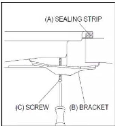
Gas supply replacement and installation guidelines:
natural_image
Diagram of a mechanical assembly showing top and bottom views with directional arrows (no text or symbols)natural_image
Illustration of a hand using a tool to press or install a mechanical component on a circular base (no text or symbols)Injector
2. Ajust del nivell mínim de la flama
natural_image
Simple line drawing of a curved line with a star and a circle, no text or symbols presentnatural_image
Four identical diagrams showing circles with curved lines and asterisks above, arranged horizontally (no text or symbols)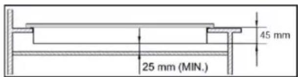
natural_image
Diagram of a mechanical component with upward and downward arrows indicating movement or force (no text or symbols)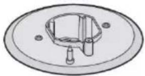
natural_image
Technical line drawing of a mechanical component with a central hexagonal feature and two mounting holes (no text or symbols)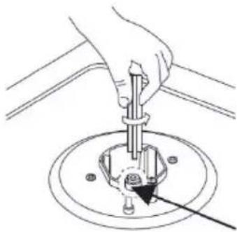
natural_image
Hand using a screwdriver to adjust or install a mechanical component (no text or symbols visible)natural_image
Simple line drawing of a curved line with a circle, an asterisk, and a dot (no text or symbols)natural_image
Four identical diagrams showing circles with curved lines and asterisks above, arranged horizontally (no text or symbols)This product enjoys the recognition and protection of the legal guarantee in accordance with current legislation. To enforce your rights or interests you must go to any of our official technical assistance services.
You can find the closest one by accessing the following web link: http://taurus-home.com/
You can also request related information by contacting us.
You can download this instruction manual and its updates at http://taurus-home.com/
Français
GARANTIE ET ASSISTANCE TECHNIQUE
COUNTRY ADDRESS PHONE
| Algeria Zone d'Activite, N° 62, Constantine 213770777756 | ||
| Argentina Av. del Libertador 1298,(B1638BEY), Vicente López (Pcia. Buenos Aires) | 541153685223 | |
| Belgium Mariëndonkstraat 5, 5154 EG, Elshout 31620401500 | ||
| Benin 359 Av. Steinmetz, 1930, Cotonou 0299-21313798 | ||
| Bulgaria | 265,Okolovrasten Pat, Mladost 4, 1766, Sofia | 35929211120 / 35929211193 |
| Burkina Faso Avenue Bassawarga, 01 BP915, Ouagadougou 226 25301038 | ||
| Congo (Republic of) 98 Blvd General Charles de Gaulle, Pointe Noire 242066776656 | ||
| Cyprus | 20, Bethlehem Str. / P.O.Box 20430, 2033, Strovolos | 35722711300 |
| Czech Republic | Milady Horakove 357/4, 568 02, Svitavy | 420 461 540 130 |
| Democratic Republic of the Congo | AV. Pont Canale N° 3440, Kinshasa | 00243-991223232 |
| Equatorial Guinea | SN Av Patricio Lumumba y C/ Jesus B, Bata | 00240 333 082958 / 00240 333 082453 |
| Equatorial Guinea | Calle de las Naciones Unidas, PO box 762, Malabo | 240333082958 / 240333082453 |
| España Avda Barcelona, S/N, 25790 Oliana (Lleida) atencioncliente@taurus.es | 902 118 050 | |
| Ethiopia Lideta Sub City Kebele 10 H.NO 124, Addis Ababa | +251 11 5518300 | |
| France | Za les bas musats 18, 89100, Malay-le-Grand | 03 86 83 90 90 |
| Gabon | BP 574, Port-Gentil Centre-ville | 24101552689 / 24101560698 |
| Ghana | Ederick Place, Accra-Ghana | 302682448 / 302682404 |
| Gibraltar 11 Horse Barrack Lane, 54000, Gibraltar 00350 200 75397 / 00350 200 | ||
| 41023 | ||
| Greece Sapfous 7-9, 10553, Athens +30 21 0373 7000 | ||
| Guinea BP 206, GN, Conakry (224) 622204545 | ||
| Hong Kong Unit H,13/F., World Tech Centre, Hong kong (852) 2448 0116 / 9197 3519 | ||
| Hungary Késmárk utca 11-13, 1158, Budapest +36 1 370 4519 | ||
| India C-175, Sector-63, Noida, Gautam Budh Nagar - 201301, Delhi | (+91) 120 4016200 | |
| Ivory Coast 01 Rue Des Carrossiers-Zone 3, B.P 3747, Abidjan 01 (RCI) | 22521251820 / 225 21 353494 | |
| Jordan 28 Basman St Down town, Amman +962 6 46 222 68 | ||
| Kuwait | P.O. BOX 3379 hawally, 32034, Hawally | +965 2200 1010 |
| Lebanon Damascus Highway; Sciale Building, Jamhour | 9615922963 | |
| Luxembourg | Mariëndonkstraat 5, 5154 EG, Elshout 31620401500 | |
| Mali | BP E2900, Dravela Bolibana | 223227216 / 223227259 |
| Marruecos | Avenue 2 Mars, Résidence Nassrallah, Appt n° 2 1er, Casablanca | (+212) 522 86 30 95 |
| Mauritania | 134 Avenue Gamal Abdener Ilot D, Nouakchott | 2225254469 / 2225251258 |
| Mexico Rosas Moreno N° 4-203 Colonia de San Rafael C.P. 06470 – Delegación Cuauhtémoc, Ciudad de México | (+52) 55 55468162 | |
| Montenegro | Rastovac bb, 81400, Niksic | +382 40 217 055 |
| Netherlands | Mariëndonkstraat 5, 5154 EG, Elshout 31620401500 | |
| Nigeria 8, Isaac; John Str,G.R.A Ikeja Lagos | 23408023360099 | |
| Paraguay | Denis Roa 155 c/ Guido Spano, Asunción | 21665100 |
| Peru | Calle los Negocios 428, Surquillo, Lima | (511) 421 6047 |
| Portugal Avenida Rainha D. Amélia, n°12-B, 1600-677, Lisboa | +351 210966324 | |
| Romania | Dudesti Pantelimon 23, 410554, Bucharest | 031.805.49.58 |
| Serbia | Rastovac bb, 81400, Niksic | +382 40 217 055 |
| Slovakia Milady Horakove 357/4, 568 02, Svitavy | 420 461 540 130 | |
| Southafrica | Unit 25 & 26, San Croy Office Park, Die Agora Road, Croydon, Kempton Park, 1619, Johannesburg | (+27) 011 392 5652 |
| Tunisia | 2, Rue de Turquie, Tunis | 21671333066 |
| Ukraine | Block 6, Ap Housing Estate Topol-2, B, 49000, Dnepropetrovsk | 380563704161 / 380563704161 |
| United Arab Emirates | P.O.BOX 8543, Dubai | 14506246200 |
| Uruguay | Luis Alberto de Herrera 3468, 11600, Montevideo | 598 2209 28 00 |
| Vietnam Lot 7 Ind. Zone for, Ha Noi | 84437658111 / 84437658110 | |

- Español
- SAFETY ADVICE AND WARNINGS:
- SAFETY INSTRUCTIONS:
- WARNINGS:
- INSTALLATION:
- HOW TO PLACE THE APPLIANCE:
- INSTALLING PROCESS:
- GAS CONNECTION:
- ELECTRICAL CONNECTION:
- WIRING DIAGRAM
- GAS ADJUSTMENT:
- Change the injector of the burners
- Adjustment of minimum level of the flame
- DESCRIPTION
- Accessories
- INSTRUCTIONS FOR USE
- AUTOMATIC IGNITION WITH FLAME FAILURE SAFETY DEVICE
- TO IGNITE A BURNER
- SAFETY AND ENERGY SAVING DEVICE
- PAN SUPPORT, CONTROL HANDLES
- TOP PLATE
- BURNERS
- FOR EU PRODUCT VERSIONS AND/OR IN CASE THAT IT IS REQUESTED IN YOUR COUNTRY:
- ECOLOGY AND RECYCLABILITY OF THE PRODUCT
- ANOMALIES AND REPAIR
- TROBLESHOOTING:
- Français
- GRILLES, COMMANDES D'ACTIONNEMENT
- Ajust del nivell mínim de la flama
- GARANTIE ET ASSISTANCE TECHNIQUE
Brand : TAURUS
Model : CG4HN/B
Category : Cooker