
UPS 15-35 SUC/TLC - Water pump Grundfos - Free user manual and instructions
Find the device manual for free UPS 15-35 SUC/TLC Grundfos in PDF.

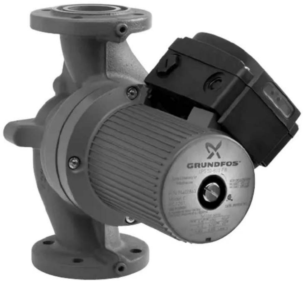
| Product type | Water pump (circulator) |
| Brand | Grundfos |
| Model | UPS 15-35 SUC/TLC |
| Connection diameter | DN 15 (1½") |
| Maximum head | 35 ft (10.7 m) |
| Maximum flow rate | Approximately 10 gal/min (38 L/min) |
| Supply voltage | 1 x 115 V or 1 x 230 V (single-phase) 3 x 208-230 V, 3 x 460 V, 3 x 575 V (three-phase) |
| Frequency | 50/60 Hz |
| Number of speeds | 3 speeds (single-phase and three-phase 208-230 V) 2 speeds (three-phase 460/575 V) |
| Thermal protection | Integrated with automatic reset (single-phase) Thermal overload switch (three-phase) |
| Liquid temperature | -10 °C to 110 °C (continuous) Up to 140 °C (intermittent) |
| Minimum inlet pressure | Variable depending on temperature (see table in manual) |
| Housing material | Cast iron |
| Rotor type | Wet rotor, lubricated and cooled by the liquid |
| Installation | Horizontal motor shaft, variable terminal box orientation |
| Weight | Approximately 5 kg |
| Dimensions (L x W x H) | Approximately 180 x 150 x 180 mm |
| Warranty | 24 months from installation (max 30 months after manufacture) |
| Application | Heating, domestic hot water, cooling water, water/glycol mixture up to 50/50 |
| Safety | Grounding mandatory, residual current circuit breaker recommended |
Frequently Asked Questions - UPS 15-35 SUC/TLC Grundfos
User questions about UPS 15-35 SUC/TLC Grundfos
0 question about this device. Answer the ones you know or ask your own.
Ask a new question about this device
Download the instructions for your Water pump in PDF format for free! Find your manual UPS 15-35 SUC/TLC - Grundfos and take your electronic device back in hand. On this page are published all the documents necessary for the use of your device. UPS 15-35 SUC/TLC by Grundfos.
USER MANUAL UPS 15-35 SUC/TLC Grundfos
Installation and operating instructions
English (US)
Installation and operating instructions 3
(AR)
36
Français (CA)
Original installation and operating instructions
CONTENTS
Page
- Limited warranty 3
- Introduction 4
2.1 Safety warning 4
3.Pre-installation checklist 4
3.1 Confirm you have the correct pump 4
3.2 Check the condition of the pump 4
3.3 Verify electrical requirements 4
3.4 Pumped liquid requirements 5
4.Installation procedures 6
4.1 Electrical preparation 6
4.2 Piping considerations 6
4.3 Connect the pump 7
4.4 Electrical connection 7
- Starting the pump 9
5.1 Vent the piping system 9
5.2 Check the direction of shaft rotation 9
5.3 Speed selection 10
6.Troubleshooting 12
6.1 Fault finding chart 12
6.2 Preliminary checks 13
6.3 Current measurement 14
6.4 Insulation resistance (lead-to-ground) 14
6.5 Winding resistance (line-to-line) 14
6.6 Winding resistance chart 16
- Replacing components 18
7.1 Removing the pump head 18
7.2 Fitting the pump head 18
7.3 Replacing the terminal box or capacitor 19
8.Disposal 19
WARNING

Prior to installation, read these installation and operating instructions. Installation and operation must comply with local regulations and accepted codes of good practice.
This booklet should be left with the owner of the pump for future reference and information regarding its operation.
1. Limited warranty
Products manufactured by GRUNDFOS PUMPS CORPORATION (Grundfos) are warranted to the original user only to be free of defects in material and workmanship for a period of
18 months from date of installation, but not more than 24 months from date of manufacture.
Grundfos' liability under this warranty shall be limited to repairing or replacing at
Grundfos' option, without charge, F.O.B.
Grundfos' factory or authorized service station, any product of Grundfos' manufacture.
Grundfos will not be liable for any costs of removal, installation, transportation, or any other charges which may arise in connection with a warranty claim. Products which are sold but not manufactured by Grundfos are subject to the warranty provided by the manufacturer of said products and not by Grundfos' warranty. Grundfos will not be liable for damage or wear to products caused by abnormal operating conditions, accident, abuse, misuse, unauthorized alteration or repair, or if the product was not installed in accordance with Grundfos' printed installation and operating instructions.
To obtain service under this warranty, the defective product must be returned to the distributor or dealer of Grundfos' products from which it was purchased together with proof of purchase and installation date, failure date, and supporting installation data. Unless otherwise provided, the distributor or dealer will contact Grundfos or an authorized service station for instructions.
Any defective product to be returned to Grundfos or a service station must be sent freight prepaid; documentation supporting the warranty claim and/or a Return Material Authorization must be included if so instructed.
GRUNDFOS WILL NOT BE LIABLE FOR ANY INCIDENTAL OR CONSEQUENTIAL
DAMAGES, LOSSES, OR EXPENSES ARISING FROM INSTALLATION, USE, OR ANY OTHER CAUSES. THERE ARE NO EXPRESS OR IMPLIED WARRANTYES, INCLUDING MERCHANTABILITY OR FITNESS FOR A PARTICULAR PURPOSE, WHICH EXTEND BEYOND THOSE WARRANTY DESCRIBED OR REFERRED TO ABOVE.
Some jurisdictions do not allow the exclusion or limitation of incidental or consequential damages and some jurisdictions do not allow limit actions on how long implied warranties may last. Therefore, the above limitations or exclusions may not apply to you. This warranty gives you specific legal rights and you may also have other rights which vary from jurisdiction to jurisdiction.
2. Introduction
2.1 Safety warning
2.1.1 Read this booklet
This booklet is designed to help a certified installer install, begin operation of and troubleshoot the Grundfos UPS pumps. The booklet should be left with the owner of the pump for future reference and information regarding its operation. Should the owner experience any problems with the pump, a certified professional should be contacted.
2.1.2 Electrical work
WARNING

All electrical work should be performed by a qualified electrician in accordance with the latest edition of the National Electrical Code, local codes and regulations.
WARNING

A faulty motor or wiring can cause electrical shock that could be fatal, whether touched directly or conducted through standing water. For this reason, proper grounding of the pump to the power supply's grounding terminal is required for safe installation and operation.
In all installations, the above-ground metal plumbing should be connected to the power supply ground as described in Article 250-80 of the National Electrical Code.
3. Pre-installation checklist
3.1 Confirm you have the correct pump
- Read the pump nameplate to make sure it is the one you ordered.
- Compare the pump's nameplate data and its performance curve (for head, gpm, etc.) with the application in which you plan to install it.
- Will the pump do what you expect it to do?
3.2 Check the condition of the pump
The shipping carton your pump came in is specially designed around your pump during production to prevent damage.
As a precaution, it should remain in the carton until you are ready to install it. At that point, look at the pump and examine it for any damage that may have occurred during shipping.
Examine any other parts of the shipment as well for any visible damage.
3.3 Verify electrical requirements
Verification of the electrical supply should be made to be certain the voltage, phase and frequency match that of the pump motor.
The proper operating voltage and other electrical information can be found on the pump nameplate.
These motors are designed to run on + / - 10% of the nameplate-rated voltage.
Wiring connection diagrams can be found inside the terminal box cover and later in these Installation and Operating Instructions. If voltage variations are larger than + / - 10% do not operate the pump.
3.4 Pumped liquid requirements
Caution
The UPS pump is intended for use with water only.
The pump can be used to circulate:
- Potable hot water
Water for hydronic heating
Water/glycol mixtures up to 50/50
Cooling water
In domestic hot-water systems it is advisable to use bronze pumps (UPS model) only for water with a degree of hardness lower than 14 grains per gallon of hardness. For water with a higher degree of hardness, a direct-coupled Grundfos TP pump is recommended.
If the pump is installed in a heating system, the water should meet the requirements of accepted standards on water quality in heating systems.
In water/glycol mixtures, in order to prevent the glycol from degrading, temperatures above those for which the fluid is rated should be avoided and time spent at high temperatures minimized.
It is also important that the system is cleaned and flushed prior to the installation of the glycol mixture.
In order to avoid problems with corrosion or precipitation, the glycol fluids should be checked and maintained regularly. If further dilution of the supplied glycol is required, follow the requirements of the supplier of the glycol.

WARNING
Glycol with the trade name DEXCOOL can harm the pump.
DEXCOOL® is a registered trademark of General Motors Corporation, used under license by Texaco Lubricants NA.
The pump is lubricated and cooled by the liquid being pumped. Therefore, the pumped liquid must always be allowed to circulate through the pump. Extended periods without circulation will cause premature wear to the bearings and excessive motor heat. The pumped liquid must also meet the following requirements:
Minimum pump inlet pressure (during operation)
| UPS model | At these liquid temperatures | |
| 167 °F/75 °C 194 °F/90 °C 230 °F/110 °C | ||
| [psi] hf [psi] hf [psi] hf | ||
| 32-40/4 0.7 1.6 2.2 5.1 21.0 48.5 | ||
| 32-80/2 0.7 1.6 5.1 11.8 23.9 55.2 | ||
| 32-160/2 11.6 26.8 16.0 37.0 34.1 78.8 | ||
| 40-40/4 0.7 1.6 4.4 10.2 23.2 53.6 | ||
| 40-80/4 0.7 1.6 1.5 3.5 18.1 41.8 | ||
| 40-80/2 6.5 15.0 10.9 25.2 29.0 67.0 | ||
| 40-160/2 5.1 11.8 9.4 21.7 27.6 63.8 | ||
| 40-240/2 11.6 26.8 16.0 37.0 34.1 78.8 | ||
| 50-40/4 0.7 1.6 2.9 6.7 21.8 50.4 | ||
| 50-80/4 0.7 1.6 4.4 10.2 23.2 53.6 | ||
| 50-80/2 4.4 10.2 8.7 20.1 26.8 61.9 | ||
| 50-160/2 11.6 26.8 16.0 37.0 34.1 78.8 | ||
| 50-240/2 10.2 23.6 14.5 33.5 32.6 75.3 | ||
| 53-55/57 4.4 10.2 8.7 20.1 26.8 61.9 | ||
| 75-69 | 11.6 26.8 16 | 37 34.1 78.8 |
| 80-40/4 11.6 26.8 16.0 37.0 34.1 78.8 | ||
| 80-80/4 14.5 33.5 18.9 43.7 37.0 85.5 | ||
| 80-160/2 21.8 50.4 26.1 60.3 43.5 | 100.5 | |
| 100-40/4 | 27.6 63.8 31.9 73.7 50.0 | 115.5 |
Liquid temperature range
Continuously:
14^ (-10^) up to 230^ (110^) .
Intermittent:
< 284 °F (140 °C) for short periods of time.
Domestic hot water:
< 140 °F (60 °C).
4. Installation procedures
WARNING

Never make any connections in the pump terminal box unless the electrical supply has been switched off.
4.1 Electrical preparation
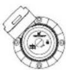
Terminal box position
At the bottom of the stator, closest to the pump housing, there are eight drain holes to allow condensed water to escape. The drain holes shall not be blocked. The drain holes must point downwards. The terminal box must therefore point upwards in one of the positions shown in fig. 1. The following terminal box positions apply whether the piping is mounted vertically or horizontally.
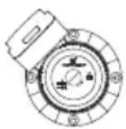
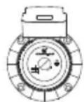
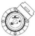
TM03 7296 4706
Fig. 1 Possible terminal box positions
Rotating the terminal box
To change the position of the terminal box, follow these steps:
WARNING

If the pump is already installed in the system, the system must be drained or the isolation valves on both sides of the pump must be closed before the allen-head screws are removed as the pumped liquid may be scalding hot and/or under pressure.
Do not start the pump until the system has been filled with liquid and vented.
- Remove the four allen-head screws holding the pump head onto the pump housing.
- Carefully lift the pump head and rotate it so the terminal box is in the desired position. DO NOT locate the terminal box beneath the pump. Make sure the O-ring is properly seated in the pump housing.
- Replace the pump head onto the pump housing.
- Tighten the allen-head screws evenly. Torque:
8 mm: 15 ft lbs
10 mm: 25 ft lbs.
- Check to make sure the rotor turns freely. Do this by removing the vent plug in the middle of the pump nameplate. Insert a medium size flat-blade screwdriver into the slot at the exposed end of the shaft. Gently turn the shaft. If it does not turn easily, repeat steps 1 to 4 above.
- The position of the nameplate can be changed by easing the outer edge of the plate at the cutout with a screwdriver. Turn the nameplate to the required position and push into place.
- Refer to page 18 and page 19 for additional instructions.
4.2 Piping considerations
Thoroughly clean and flush all dirt and sediment from the system before attempting to install the pump.
Location in the piping line
The pump should never be located at the lowest point of the piping system, where dirt and sediment collect. Nor should it be located at the highest point of the piping system, where air accumulates.
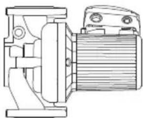
Mounting positions
The arrows on the flanges of the pump indicate the direction of water flow. Although the UPS may be installed in either vertical or horizontal piping, the motor shaft must always remain horizontal, as shown in fig. 1 and fig. 2.
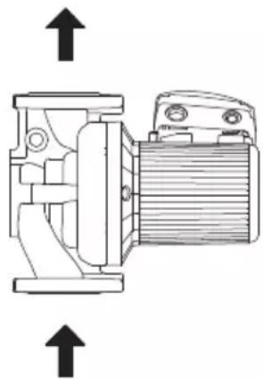
TM03 7290 4706
Fig. 2 Direction of water flow through the pump

Pumps installed outdoors must be protected by a ventilated, watertight cover to keep out moisture and dirt.
WARNING

The pump must be positioned so that someone cannot accidentally come into contact with the hot surfaces of the pump.
4.3 Connect the pump
Install the pump into the piping system.
Grundfos recommends that pressure gauges be installed in the inlet and discharge flanges or pipes to check pump and system performance.
4.4 Electrical connection
The electrical connection and protection should be carried out in accordance with the latest edition of the National Electrical Code, local codes and regulations by a qualified electrician.
WARNING

Never make any connections in the pump terminal box unless the electrical supply has been switched off.
The pump must be grounded.
The pump must be connected to an external main power switch.
The operating voltage and frequency are marked on the pump nameplate. Make sure that the motor is suitable for the electrical supply it is being installed to.
The pump should be grounded to protect against indirect contact and a ground fault interrupter can be used as extra protection.
Multi-speed pump (single-phase)
All single-phase pumps are equipped with built-in, automatic resetting, thermal overload protection. The pump is protected at all three speeds.
Multi-speed pump (three-phase)
The pump must be connected to the electrical supply via an external contactor. The contactor must be connected to the built-in thermal overload switch terminals T1 and T2 (3 x 208-230 V) or P1 and P2 (3 x 460 V and 575 V) to protect the pump against overloading at all three speeds.
OR: If the pump is protected by means of a motor starter, the starter must be set to the current consumption of the pump at the selected speed. The motor starter setting must be changed every time the pump speed is changed. The current consumption at the individual speeds is stated on the pump nameplate.
Figures 4, 6, 7, 9, and 10 on the next pages show the possible connections.
4.4.1 UPS 1 x 115 V and 1 x 230 V terminal box
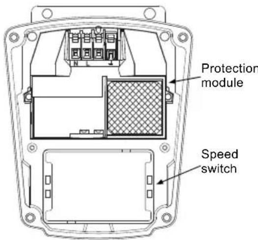
TM03 7744 4806TM03 7743 4806
Fig. 3 UPS 1 × 115V and 1 × 230V terminal box
All UPS single-phase pumps come with a protection module and a speed switch as shown in fig. 3. All pumps are equipped with built-in, automatic resetting, thermal overload protection. The pump is protected at all three speeds.
Wiring diagrams
Figure 4 shows the electrical connections for a single-phase pump with protection module.
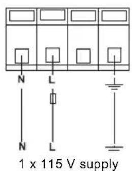
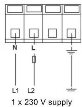
Fig. 4 1 x 115 V and 1 x 230 V supply

Provide electrical disconnect and current protection as per local electrical codes.
K = External contactor sized to FL and LR pump current.
4.4.2 UPS 3 x 208-230 V terminal box
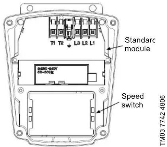
Fig. 5 UPS 3 × 208 - 230V terminal box
All UPS pumps with three-phase x 208-230 V come with a standard module and a speed switch as shown in fig. 5. All pumps are equipped with an internal thermal overload switch (terminals T1 and T2, to be connected to an external contactor) to protect the pump at all three speeds.
Wiring diagrams
Figure 6 shows the electrical connections when using an external changeover contact (safety circuit) for start/stop push button station.
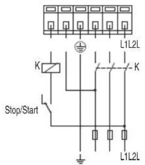
TM03 7892 5106
Fig. 6 External changeover contact
Auxiliary contacts rated for supply voltage.
Figure 7 shows the electrical connections when using external impulse contacts (momentary contacts) for start/stop push button station.
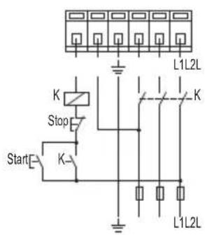
TM03 7740 4806
Fig. 7 External impulse contacts
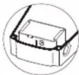
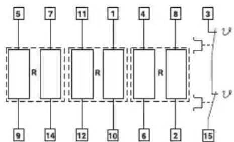
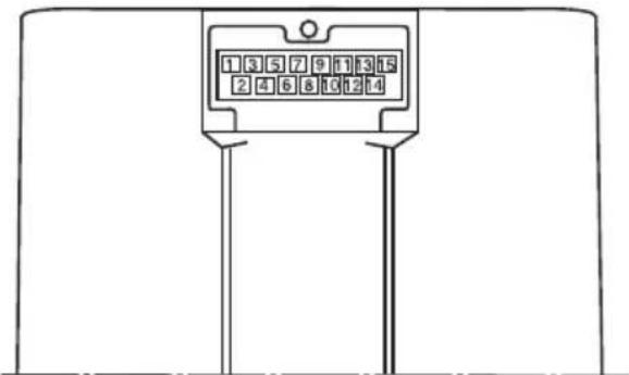
4.4.3 UPS 3 x 460 V and 575 V terminal box
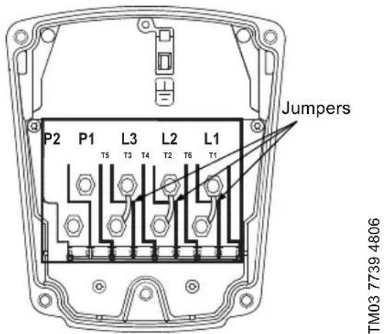
Fig. 8 UPS 3 x 460 V and 575 V terminal box
All UPS pumps with three-phase x 460 V and 575 V terminal boxes (fig. 8) come with a special two-speed terminal box. The speed is changed by the orientation of the jumpers as shown on page 11. All pumps are equipped with an internal thermal overload switch (terminals P1 and P2) to be connected to external contactor.
Wiring diagrams
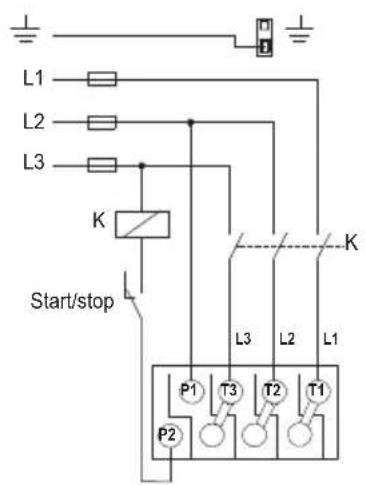
Figure 9 shows the electrical connections when using an external changeover contact (safety circuit) for start/stop push button station.
TM03 7738 5106
Fig. 9 External changeover contact
Auxiliary contacts rated for supply voltage.
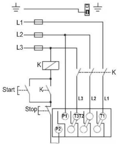
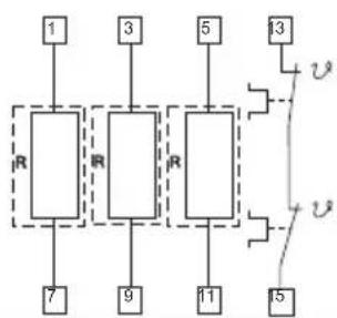
Figure 10 shows the electrical connections when using external impulse contacts (momentary contacts) for start/stop push button station.
Fig. 10 External impulse contacts
TM03 7737 4806
5. Starting the pump
5.1 Vent the piping system
After the pump has been installed and the electrical connections made, the piping system must be vented.
Caut
Never operate the pump dry - the system must first be filled with liquid and vented.
Not
Do not vent the piping system through the pump.
Instead, follow these steps:
- Fill and pressurize the system with liquid, and vent all trapped air from the piping by suitable means.
- If any isolation valves are used, make sure they are OPEN.
WARNING

If the vent screw is to be loosened, care should be taken to ensure that the escaping scalding hot liquid does not cause personal injury or damage to components (see fig. 12).
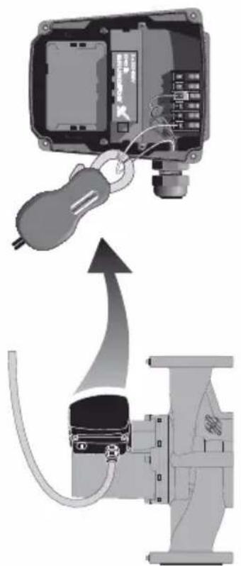
5.2 Check the direction of shaft rotation
Applies to 460 V and 575 V two-speed models only
(The direction of rotation of three-speed pumps is checked by means of the fault finding chart, page 12 and page 13).
- Make sure that the power is OFF.
- Unscrew and remove the vent plug located at the center of the nameplate.
- Insert a small, flat-blade screwdriver into the slot in the end of the motor shaft (see fig. 12). Rotate the shaft with the screwdriver to make sure it does so freely.
- Bump the pump and watch to see which direction the shaft rotates. The shaft must rotate in the counterclockwise direction as shown on the nameplate (see fig. 11).
- If the pump shaft is rotating incorrectly, disconnect the power and interchange any two power leads in the terminal box.
- Check once again for proper counterclockwise rotation. When it is rotating correctly, replace the vent plug.
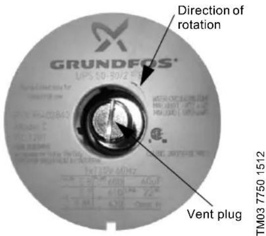
Fig. 11 Vent plug and direction of rotation
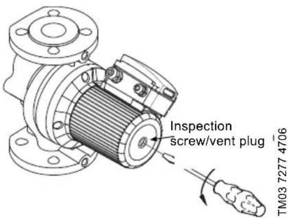
Fig. 12 Removing the vent plug
5.3 Speed selection
5.3.1 Three-speed pumps, all models except 3 × 460 ~V and 575 ~V
The speed switch in the terminal box can be turned to three positions. The speed in the three positions appears in the table below (also see fig. 13).
| Switch position | Speed in % of maximum speed | |
| Single-phase pumps | Three-phase pumps | |
| 1 approx. 60 % approx. 70 % | ||
| 2 approx. 80 % approx. 85 % | ||
| 3 100 % 100 % | ||
Changing to lower speeds offers considerable reduction in energy consumption and less noise in the system.
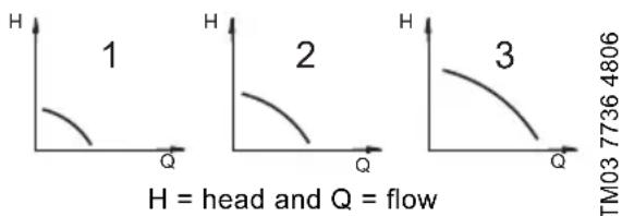
Fig. 13 Pump performance at speed settings
WARNING

Never make any connections in the pump terminal box unless the electrical supply has been switched off.
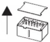
Change the pump performance as follows:
- Switch off the electrical supply to the pump at the main circuit breaker.
The green indicator light in the terminal box must be off. - Remove the terminal box cover by loosening the four screws in the cover.
- Pull out the speed switch module and re-insert it so that the desired speed is visible through the window in the terminal box (see fig. 14).
SPEED
SPEED
1
2
SPEED
3
TMM 77354806
Fig. 14 Speed switch module
When changing to and from speed 1, the cover of the speed switch module must be removed and fitted on the other side of the switch.
- Fit the terminal box cover back onto the terminal box and tighten the four screws in the cover.
- Switch on the electrical supply. Check that the green indicator light is permanently on or flashing.

The speed switch module must never be used as an on/off switch.
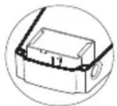
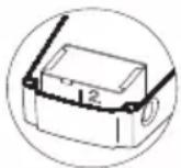
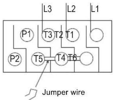
5.3.2 Two-speed pumps, 3 × 460V and 575V
The speed setting in the terminal box can be changed to two positions. The speed in the two positions appears in the table below (also see fig. 13 on page 10).
| Speed step Speed in % of max. speed |
| 1 approx. 75 % |
| 2 100 % |

WARNING
Never make any connections in the pump terminal box unless the electrical supply has been switched off.
Change the pump performance as follows:
The speed is changed by the position of the jumpers in the terminals. The jumpers are fitted according to:
- figure 15 for speed 1 - low speed
- figure 16 for speed 2 - high speed.
TM03 7734 4806
Fig. 15 Speed 1 (low speed)
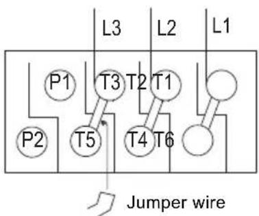
Fig. 16 Speed 2 (high speed)
TM03 7733 4806
6. Troubleshooting
6.1 Fault finding chart
WARNING

Before removing the terminal box cover, make sure that the electrical supply has been switched off and that it cannot be accidentally switched on.
The pumped liquid may be scalding hot and under high pressure. Before any removal or dismantling of the pump, the system must be drained or the isolation valves on both sides of the pump must be closed.
Fault Cause Remedy
| 1. The pump does not run. None of the indicator lights are on. | a) One fuse in the installation is blown. | Replace the fuse. |
| b) External circuit breaker is switched off. | Switch the circuit breaker on. | |
| c) Current-/voltage-operated ground fault interrupter has tripped. | Repair the insulation defects and reset the interrupter. | |
| d) The pump's internal thermal overload switch has cut out (standard module only). | Check that the liquid temperature falls within the specified range. With external on/off changeover contact: The pump will restart automatically when it has cooled to normal temperature. With external on/off impulse contacts: The pump can be restarted when it has cooled to normal temperature. | |
| 2. The pump does not run. The green indicator light is on. | a) Rotor blocked, but the pump hasn't been cut out by the thermal overload switch. | Switch off the electrical supply and clean/repair the pump. |
| b) The speed switch module has not been fitted. | Switch off the electrical supply at the external circuit breaker and fit the speed switch module into position. | |
| 3. Three-phase pumps only: The pump is running. The red and green indicator lights are on. | a) The pump is running with the wrong direction of rotation. | Switch off the electrical supply at the external circuit breaker and interchange any two phases (leads) in the pump terminal box. |
| 4. Noise in the system. The green indicator light is on. | a) Air in the system. Vent the system. | |
| b) The pump flow is too high. Reduce the pump performance. | ||
| c) The pressure is too high. Reduce the pump performance. | ||
| 5. Noise in the pump. The green indicator light is on. | a) Air in the pump. Vent the pump. | |
| b) The inlet pressure is too low. | Increase the inlet pressure and/or check the air volume in the expansion tank (if installed). | |
| 6. Insufficient heat in some places in the heating system. | a) The pump performance is too low. | Increase the pump performance, if possible, or replace the pump with a pump with higher flow. |
| Fault Cause Remedy | ||
| 7. Single-phase pumps with protection module (only). The pump does not run. The red indicator light is on. The green indicator light is off. | a) The pump has been cut out by the thermal overload switch due to high liquid temperature or blocked rotor. | Check that the liquid temperature falls within the specified range. The pump will restart automatically when it has cooled to normal temperature. NOTE: If the thermal overload switch has cut out the pump three times within a short period, the pump must be restarted manually by switching off the electrical supply. |
| b) The speed switch module has not been fitted. | Switch off the electrical supply by means of the external mains switch and fit the speed switch module. | |
6.2 Preliminary checks
Supply voltage
To check the voltage being supplied to the motor, use a voltmeter.
WARNING

Be careful, since power is still being supplied to the pump. Do not touch the voltmeter leads together while they are in contact with the power lines.
Evaluation
When the motor is under load, the voltage should be within 10% (+ or -) of the nameplate voltage. Any variation larger than this may indicate a poor electrical supply and can cause damage to the motor windings. The motor should not be operated under these conditions. Contact your power supplier to correct the problem or change the motor to one requiring the voltage you are receiving.
Single-phase motors Three-phase motors
| Touch one voltmeter lead to each of the lines supplying power to the pump: • L and N for 115 V circuits • L1 and L2 for 230 V circuits. | Touch a voltmeter lead to: • Power leads L1 and L2 • Power leads L2 and L3 • Power leads L3 and L1. These tests should give a reading of full line voltage. |
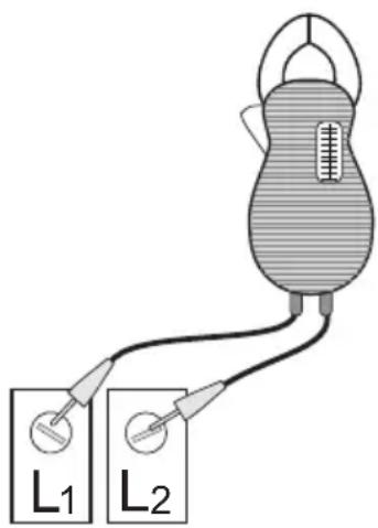
Fig. 17 Checking single-phase power
6.3 Current measurement
To check the current, use an ammeter.
To do so, follow these steps:
- Make sure the pump is operating.
- Set the ammeter to the proper scale.
- Place the tongs of the ammeter around the leg to be measured.
- Compare the results with the amp draw information on the motor nameplate.
- Repeat for the other legs.
Evaluation
If the current draw exceeds the listed nameplate amps, or if the current imbalance is greater than 5% between each leg on three-phase units, then check the following:
The voltage supplied to the pump may be too high or too low.
The contacts on the motor starter may be burned.
The terminals in the starter or terminal box may be loose.
- There may be a winding defect. Check the winding and insulation resistance.
- The motor windings may be shorted or grounded.
The pump may be damaged in some way and may be causing a motor overload.
- A voltage supply or balance problem may exist.
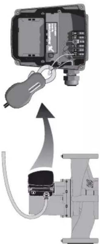
Fig. 18 Current measurement
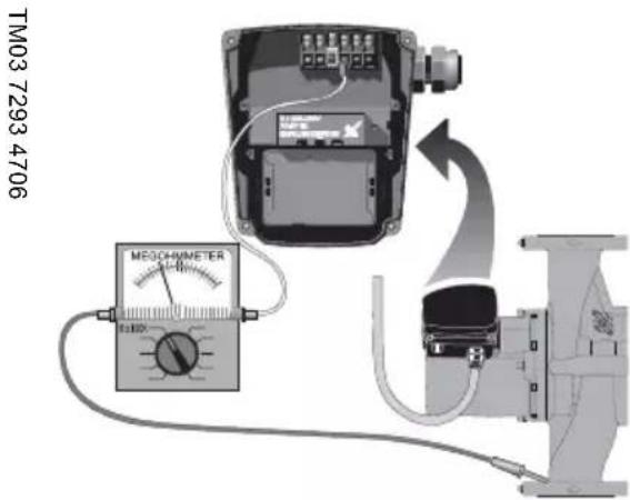
6.4 Insulation resistance (lead-to-ground)
To check the insulation resistance (lead-to-ground) of the motor and leads, a megohmmeter is required.
To do so, follow these steps:
- Turn the POWER OFF.
- Disconnect all electrical leads to the motor.
- Set the scale selector on the megohmmeter to R x 100K, touch its leads together, and adjust the indicator to zero.
- Touch the leads of the megohmmeter individually to each of the motor leads and to ground (i.e. L1 to ground; L2 to ground, etc.).
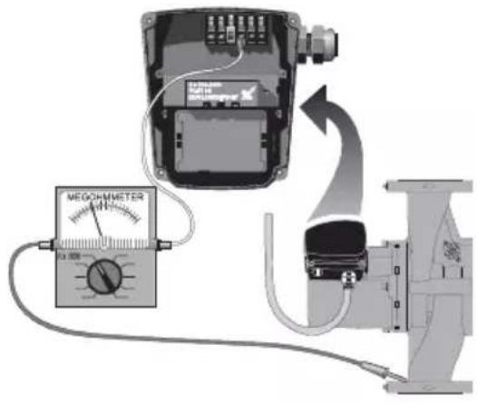
Fig. 19 Insulation resistance measurement
Evaluation
The resistance values for new motors must exceed 1,000,000 ohms. If they do not, replace the motor.
6.5 Winding resistance (line-to-line)
To check the winding resistance of the motor windings, a megohmmeter is required.
To do so, follow these steps:
- Turn the POWER OFF.
- Disconnect all electrical leads to the motor.
- Set the scale selector on the megohmmeter to R × 1 , touch its leads together, and adjust the indicator to zero.
- Using the charts below for reference, touch the leads of the megohmmeter to the appropriate pair of connectors. Check all pairs that are present and write down and label (RA, RS1, RS2, R) all readings.
- Compare your readings to the matching model, phase and voltage on the chart on page 16 and page 17.
Evaluation
The resistance values must fall within the tolerances listed on page 16 or page 17. If they do not, replace the motor.
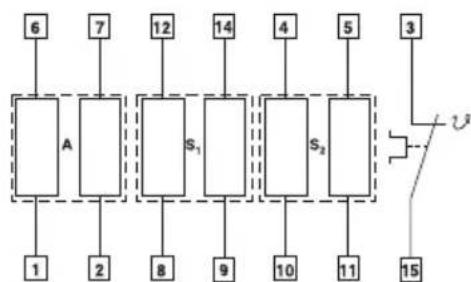
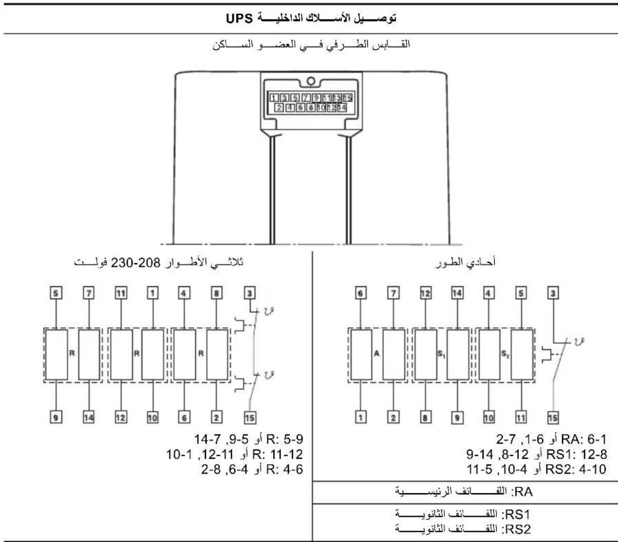
Internal wiring UPS
Terminal plug in stator
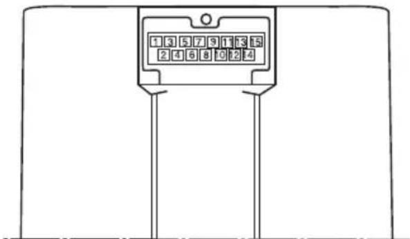
Single-phase Three-phase 208-230 V
RA:6-1 or 6-1,7-2
RS1: 12-8 or 12-8, 14-9
RS2:4-10 or 4-10,5-11
RA: Main winding
RS_1 : Auxiliary winding
RS2: Auxiliary winding
R: 5-9 or 5-9, 7-14
R: 11-12 or 11-12, 1-10
R: 4-6 or 4-6, 8-2
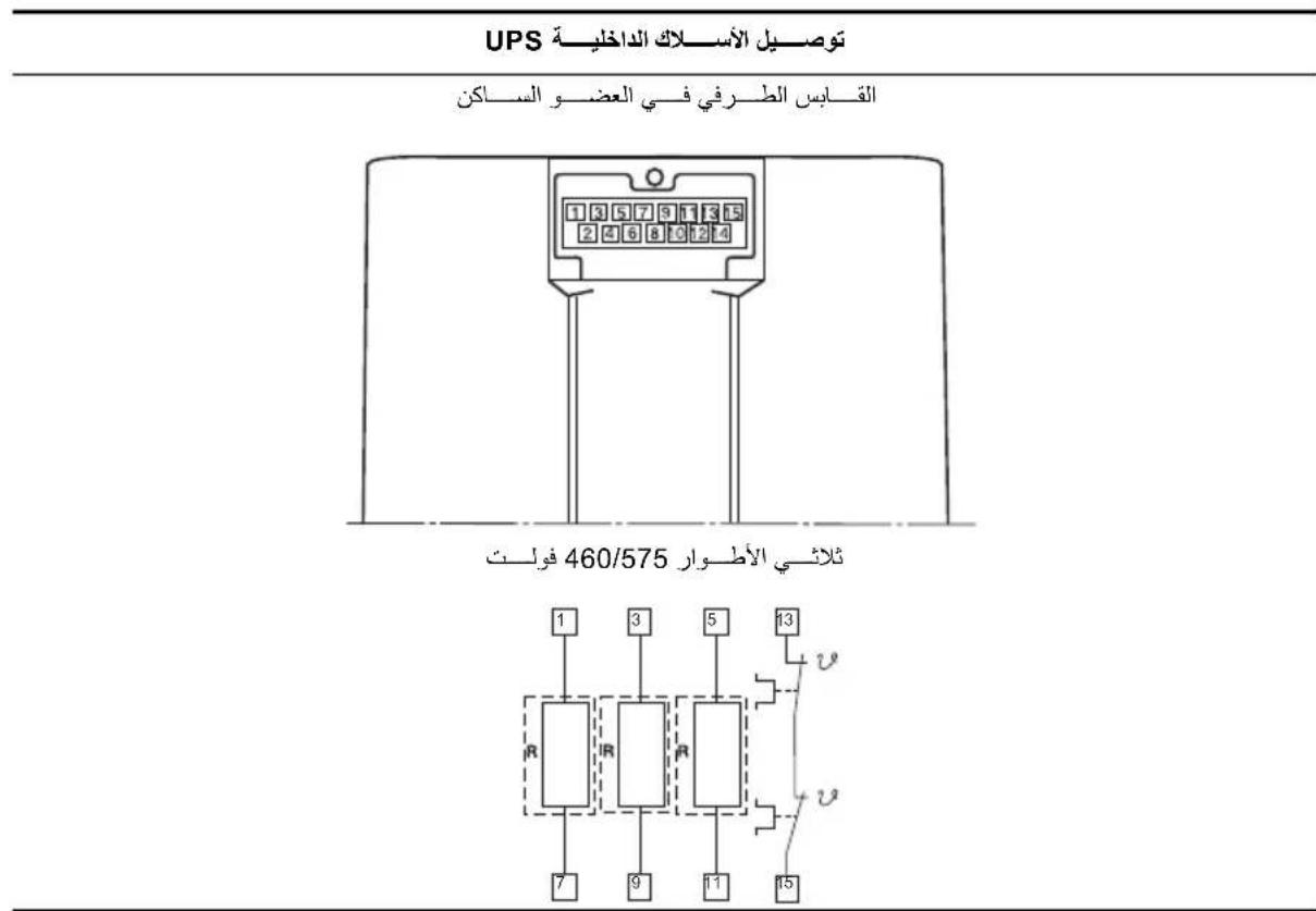
Internal wiring UPS
Terminal plug in stator
Three-phase 460/575 V
| Pump type Voltage | [Ω] 68 °F - 122 °F (20 °C - 50 °C) | ||||
| R | R | A 1 | RRS2 | ||
| UPS 32-40/4 | 1 x 115 V 17.8 - 23.2 3.95 - 5.20 9.40 - 12.4 | ||||
| 1 x 230 V 70.0 - 91.5 17.0 - 22.2 39.5 - 52.0 | |||||
| 3 x 208-230 V 180 - 236 | |||||
| 3 x 460 V 360 - 470 | |||||
| 3 x 575 V 575 - 750 | |||||
| UPS 32-80/2 | 1 x 115 V 9.55 - 12.6 3.05 - 4.00 6.70 - 8.80 | ||||
| 1 x 230 V 19.4 - 25.5 5.45 - 7.10 12.6 - 16.4 | |||||
| 3 x 208-230 V 44.0 - 57.5 | |||||
| 3 x 460 V 83.5 - 110 | |||||
| 3 x 575 V 132 - 174 | |||||
| UPS 32-160/2 | 1 x 115 V 4.15 - 5.45 1.20 - 1.56 2.65 - 3.50 | ||||
| 1 x 230 V 8.30 - 10.8 2.20 - 2.90 5.05 - 6.65 | |||||
| 3 x 208-230 V 26.0 - 34.0 | |||||
| 3 x 460 V 53.5 - 70.0 | |||||
| 3 x 575 V 84.5 - 110 | |||||
| UPS 40-40/4 | 1 x 115 V 11.4 - 15.0 2.95 - 3.85 5.60 - 7.35 | ||||
| 1 x 230 V 50.5 - 66.5 14.0 - 18.4 25.5 - 34.0 | |||||
| 3 x 208-230 V 118 - 154 | |||||
| 3 x 460 V 234 - 310 | |||||
| 3 x 575 V 360 - 475 | |||||
| UPS 40-80/2 | 1 x 115 V 5.60 - 7.35 1.84 - 2.42 4.50 - 5.90 | ||||
| 1 x 230 V 11.0 - 14.4 3.95 - 5.20 8.55 - 11.2 | |||||
| 3 x 208-230 V 32.0 - 42.0 | |||||
| 3 x 460 V 64.0 - 84.0 | |||||
| 3 x 575 V 102 - 132 | |||||
| UPS 40-80/4 | 1 x 115 V 4.15 - 5.45 1.94 - 2.55 3.30 - 4.35 | ||||
| 1 x 230 V 8.10 - 10.6 3.05 - 4.00 4.60 - 6.05 | |||||
| 3 x 208-230 V 46.5 - 61.0 | |||||
| 3 x 460 V 90.5 - 118 | |||||
| 3 x 575 V 164 - 216 | |||||
| UPS 40-160/2 | 1 x 115 V 2.85 - 3.75 1.10 - 1.44 1.94 - 2.55 | ||||
| 1 x 230 V 5.60 - 7.35 2.02 - 2.66 3.75 - 4.95 | |||||
| 3 x 208-230 V 22.8 - 30.0 | |||||
| 3 x 460 V 45.5 - 59.5 | |||||
| 3 x 575 V 72.0 - 95.0 | |||||
| UPS 40-240/2 | 1 x 230 V 6.80 - 8.95 2.02 - 2.65 3.70 - 4.85 | ||||
| 3 x 208-230 V 11.0 - 14.4 | |||||
| 3 x 460 V 22.0 - 29.0 | |||||
| 3 x 575 V 35.0 - 45.5 | |||||
s
| Pump type Voltage | [Ω] 68 °F - 122 °F (20 °C - 50 °C) | ||||
| R | R | A 1 | RRS2 | ||
| UPS 50-40/4 | 1 x 115 V 6.55 - 8.55 2.12 - 2.80 4.30 - 5.65 | ||||
| 1 x 230 V 25.0 - 33.0 8.30 - 10.8 15.0 - 19.8 | |||||
| 3 x 208-230 V 57.5 - 75.0 | |||||
| 3 x 460 V 114 - 148 | |||||
| 3 x 575 V 184 - 242 | |||||
| UPS 50-80/2 | 1 x 115 V 4.15 - 5.45 1.20 - 1.56 2.65 - 3.50 | ||||
| 1 x 230 V 8.30 - 10.80 2.20 - 2.90 5.05 - 6.65 | |||||
| 3 x 208-230 V 26.0 - 34.0 | |||||
| 3 x 460 V 33.5 - 70.0 | |||||
| 3 x 575 V 84.5 - 110 | |||||
| UPS 50-80/4 | 1 x 115 V 2.75 - 3.60 1.74 - 2.30 2.85 - 3.75 | ||||
| 1 x 230 V 5.50 - 7.25 2.65 - 3.50 4.95 - 6.50 | |||||
| 3 x 208-230 V 37.0 - 49.0 | |||||
| 3 x 460 V 79.0 - 104 | |||||
| 3 x 575 V 120 - 156 | |||||
| UPS 50-160/2 | 1 x 230 V 6.80 - 8.95 2.02 - 2.65 3.70 - 4.85 | ||||
| 3 x 208-230 V 12.4 - 16.2 | |||||
| 3 x 460 V 24.2 - 31.5 | |||||
| 3 x 575 V 37.5 - 49.5 | |||||
| UPS 50-240/2 | 3 x 208-230 V 7.80 - 10.2 | ||||
| 3 x 460 V 15.6 - 20.6 | |||||
| 3 x 575 V 25.0 - 33.0 | |||||
| UPS 53-55/57 | 1 x 115 V 4.15 - 5.45 1.20 - 1.56 2.65 - 3.50 | ||||
| 1 x 230 V 8.30 - 10.80 2.20 - 2.90 5.05 - 6.65 | |||||
| 3 × 208-230 V 26.0 - 34.0 | |||||
| 3 x 460 V 33.5 - 70.0 | |||||
| 3 x 575 V 84.5 - 110 | |||||
| UPS 75-69 | 1 x 230 V 6.80 - 8.95 2.02 - 2.65 3.70 - 4.85 | ||||
| 3 x 208-230 V 12.4 - 16.2 | |||||
| 3 x 460 V 24.2 - 31.5 | |||||
| 3 x 575 V 37.5 - 49.5 | |||||
| UPS 80-40/4 | 3 x 208-230 V 46.5 - 61.0 | ||||
| 3 x 460 V 90.5 - 118 | |||||
| 3 x 575 V 164 - 216 | |||||
| UPS 80-80/4 3 x 208-230 V 23.6 - 31.0 | |||||
| UPS 80 -160/2 | 3 x 208-230 V 7.80 - 10.2 | ||||
| 3 x 460 V 15.6 - 20.6 | |||||
| 3 x 575 V 25.0 - 33.0 | |||||
| UPS 100-40/4 | 3 x 208-230 V 27.5 - 36.0 | ||||
| 3 x 460 V 54.5 - 71.5 | |||||
| 3 x 575 V 86.0 - 114 | |||||
7. Replacing components
7.1 Removing the pump head
- Disconnect or TURN OFF the power supply.
- Close any isolation valves on either side of the pump to avoid draining the system of liquid.
- Disconnect the electrical leads from the terminal box.
- Disconnect and remove the conduit from the terminal box.
- Loosen and remove the four allen-head screws (8 or 10mm ) which connect the pump head housing to the pump housing.
- Remove the pump head from the pump housing.
- Clean the machined surfaces in the pump housing of any foreign material.
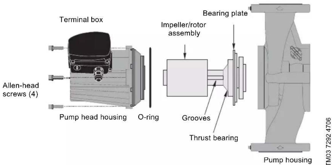
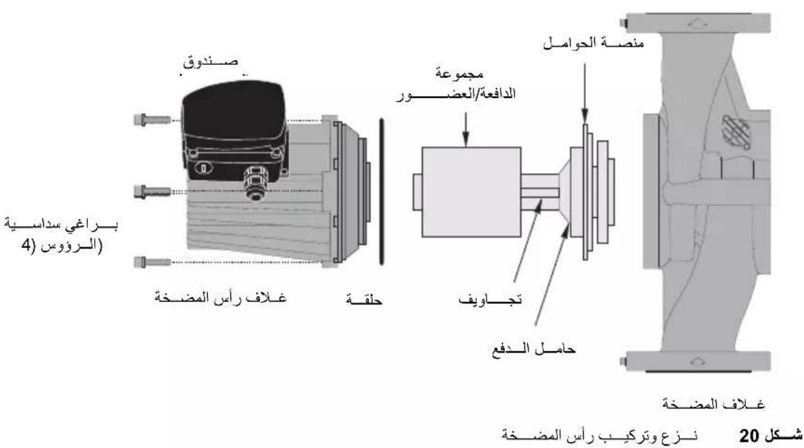
Fig. 20 Removing and fitting the pump head
7.2 Fitting the pump head
- Carefully remove the new pump head assembly from its packaging. Separate the impeller/rotor assembly from the new pump head.
- While holding the thrust bearing, carefully place the impeller/rotor assembly into the pump housing. The bearing plate should fit snugly into the lowest machined surface in the pump housing.
- Make sure that the impeller/rotor assembly can rotate freely.
- Place the O-ring over the rotor and locate it into the inner diameter of the pump housing.
-
Carefully place the pump head housing over the rotor and rotate it so the terminal box is in the position you wish, see section 4.1 under Terminal box position.
-
Make sure the pump head housing is properly seated on the pump housing. Do not force the two together - if there is binding, disassemble them and repeat steps 2 to 6. Tighten the allen-head screws evenly to secure the pump head. Torque: 8 mm: 15 ft lb 10 mm: 25 ft lb.
- Check to make sure the motor shaft turns freely, as explained in section 4.1 under Rotating the terminal box.
7.3 Replacing the terminal box or capacitor
If the terminal box is replaced, make certain the electrical information listed on the new box matches the information listed on the old box, and that it is compatible with the pump and incoming electrical supply.
For all terminal boxes, it is very important to tightly secure the frame grounding screw through the terminal box, so that a proper connection between the terminal box and motor is made.
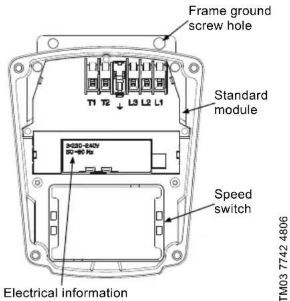
Fig. 21 Terminal box
| All | 1. Before replacing the terminal box or capacitor, make sure the power is OFF. |
| 2. Remove the terminal box cover by completely loosening all four torx/standard screws. | |
| 3. Remove the speed switch (noting its position) by pulling firmly and evenly on both sides of it. (Not for 460/575 V). | |
| Capacitor | a.4. Capacitor replacement, single-phase pumps only: Disconnect the two connector clips from the capacitor and unscrew the complete plastic strain relief nut. Remove capacitor wire and strain relief. |
| a.5. Screw in new complete strain relief nut and connect new clip connectors. Pull excess sheathed cable out of terminal box, being sure to leave at least 1/8" of sheath inside of terminal box. | |
| Terminal box | b.4. Terminal box replacement: Disconnect all wiring, remove the three phillips-head screws holding the terminal box in place and remove the terminal box by pulling firmly and evenly on both sides. |
| b.5. Check that the clear rubber gasket is in place around the terminal box connector stem, carefully press the terminal box into the stator socket, replace the three phillips-head terminal box screws and replace wiring. | |
| All | 6. Replace the speed switch to its proper position, making sure to push it all the way in. (Not for 460/575 V). |
| 7. Replace the terminal box cover and tighten all four torx/standard screws. | |
| 8. Switch on electrical power supply. The pump is now ready for operation. |
8. Disposal
This product or parts of it must be disposed of in an environmentally sound way:
- Use the public or private waste collection service.
- If this is not possible, contact the nearest Grundfos company or service workshop.
Subject to alterations.
aalal alal aalal aalal 1
2
a a 2 j 3
y
6.2
1
1
2
3
4
5
3.1 3.1
as iall Jy jia as iial 6j1.6
21 7
| [Ω] 68 °F - 122 °F (20 °C - 50 °C) | ### ### ### | |||
| RS2 | RS1 | RA | R | |
| 4,30 - 5,65 2,12 - 2,80 6,55 - 8,55 1 x 115 V | UPS 50-40/4 | |||
| 15,0 - 19,8 8,30 - 10,8 25,0 - 33,0 1 x 230 V | ||||
| 57,5 - 75,0 3 x 208-230 V | ||||
| 114 - 148 3 x 460 V | ||||
| 184 - 242 3 x 575 V | ||||
| 2,65 - 3,50 1,20 - 1,56 4,15 - 5,45 1 x 115 V | UPS 50-80/2 | |||
| 5,05 - 6,65 2,20 - 2,90 8,30 - 10,80 1 x 230 V | ||||
| 26,0 - 34,0 3 x 208-230 V | ||||
| 33,5 - 70,0 3 x 460 V | ||||
| 84,5 - 110 3 x 575 V | ||||
| 2,85 - 3,75 1,74 - 2,30 2,75 - 3,60 1 x 115 V | UPS 50-80/4 | |||
| 4,95 - 6,50 2,65 - 3,50 5,50 - 7,25 1 x 230 V | ||||
| 37,0 - 49,0 3 x 208-230 V | ||||
| 79,0 - 104 3 x 460 V | ||||
| 120 - 156 3 x 575 V | ||||
| 3,70 - 4,85 2,02 - 2,65 6,80 - 8,95 1 x 230 V | UPS 50-160/2 | |||
| 12,4 - 16,2 3 x 208-230 V | ||||
| 24,2 - 31,5 3 x 460 V | ||||
| 37,5 - 49,5 3 x 575 V | ||||
| 7,80 - 10,2 3 x 208-230 V | ||||
| 25,0 - 33,0 3 x 575 V | ||||
| 2,65 - 3,50 1,20 - 1,56 4,15 - 5,45 1 x 115 V | UPS 53-55/57 | |||
| 5,05 - 6,65 2,20 - 2,90 8,30 - 10,80 1 x 230 V | ||||
| 26,0 - 34,0 3 x 208-230 V | ||||
| 33,5 - 70,0 3 x 46O V | ||||
| 84,5 - 110 3 x 575 V | ||||
| 3,70 - 4,85 2,02 - 2,65 6,80 - 8,95 1 x 230 V | UPS 75-69 | |||
| 12,4 - 16,2 3 x 208-230 V | ||||
| 24,2 - 31,5 3 x 460 V | ||||
| 37,5 - 49,5 3 x 575 V | ||||
| 46,5 - 61,0 3 x 208-230 V | ||||
| 164 - 216 3 x 575 V | ||||
| 23,6 - 31,0 3 x 208-230 V UPS 80-80/4 | ||||
| 7,80 - 10,2 3 x 208-230 V | ||||
| UPS 80 -160/215,6 - 20 | ||||
| 25,0 - 33,0 3 x 575 V | ||||
| 27,5 - 36,0 3 x 208-230 V | ||||
| UPS 100-40/454,5 - 71 | ||||
| 86,0 - 114 3 x 575 V | ||||
| [Ω] 68°F - 122°F (20°C - 50°C) | الجِدَهُّيْ | الجِدَهُّيْ | ||
| RS2 RS1 RA R | ||||
| 9,40 - 12,4 3,95 - 5,20 17,8 - 23,2 1 x 115 V | UPS 32-40/4 | |||
| 39,5 - 52,0 17,0 - 22,2 70,0 - 91,5 1 x 230 V | ||||
| 180 - 236 3 x 208-230 V | ||||
| 360 - 470 | 3 x 460 V | |||
| 575 - 750 | 3 x 575 V | |||
| 6,70 - 8,80 3,05 - 4,00 9,55 - 12,6 1 x 115 V | UPS 32-80/2 | |||
| 12,6 - 16,4 5,45 - 7,10 19,4 - 25,5 1 x 230 V | ||||
| 44,0 - 57,5 3 x 208-230 V | ||||
| 83,5 - 110 | 3 x 460 V | |||
| 132 - 174 | 3 x 575 V | |||
| 2,65 - 3,50 1,20 - 1,56 4,15 - 5,45 1 x 115 V | UPS 32-160/2 | |||
| 5,05 - 6,65 2,20 - 2,90 8,30 - 10,8 1 x 230 V | ||||
| 26,0 - 34,0 3 x 208-230 V | ||||
| 53,5 - 70,0 | 3 x 460 V | |||
| 84,5 - 110 | 3 x 575 V | |||
| 5,60 - 7,35 2,95 - 3,85 11,4 - 15,0 | 1 x 115 V | UPS 40-40/4 | ||
| 25,5 - 34,0 14,0 - 18,4 50,5 - 66,5 1 x 230 V | ||||
| 118 - 154 3 x 208-230 V | ||||
| 234 - 310 | 3 x 460 V | |||
| 360 - 475 | 3 x 575 V | |||
| 4,50 - 5,90 1,84 - 2,42 5,60 - 7,35 1 x 115 V | UPS 40-80/2 | |||
| 8,55 - 11,2 3,95 - 5,20 | 11,0 - 14,4 1 x 230 V | |||
| 32,0 - 42,0 3 x 208-230 V | ||||
| 64,0 - 84,0 | 3 x 460 V | |||
| 102 - 132 | 3 x 575 V | |||
| 3,30 - 4,35 1,94 - 2,55 4,15 - 5,45 1 x 115 V | UPS 40-80/4 | |||
| 4,60 - 6,05 3,05 - 4,00 8,10 - 10,6 1 x 230 V | ||||
| 46,5 - 61,0 3 x 208-230 V | ||||
| 90,5 - 118 | 3 x 460 V | |||
| 164 - 216 | 3 x 575 V | |||
| 1,94 - 2,55 1,10 - 1,44 2,85 - 3,75 1 x 115 V | UPS 40-160/2 | |||
| 3,75 - 4,95 2,02 - 2,66 5,60 - 7,35 1 x 230 V | ||||
| 22,8 - 30,0 3 x 208-230 V | ||||
| 45,5 - 59,5 | 3 x 460 V | |||
| 72,0 - 95,0 | 3 x 575 V | |||
| 3,70 - 4,85 2,02 - 2,65 6,80 - 8,95 1 x 230 V | UPS 40-240/2 | |||
| 11,0 - 14,4 3 x 208-230 V | ||||
| 22,0 - 29,0 | 3 x 460 V | |||
| 35,0 - 45,5 | 3 x 575 V | |||
(5.4
aolal (jai jai bail) jai a gao
S_ OBC = 12 · BO · CD = 12 × CD × 5
1,2,3 1,4,5 2,3,4
a ball 1
2
Rle jaoj 100
100Kx
( x,y) 0
J 4
L2:J L1
.
jzai aiaa
19
1 + u1 - 1 = ( 1 + u) u1 < 1 = u
1.000.000
(bi) (bi) 5.5
a 1
y
1,2,·s ,n
1
2
Rle jao le all 3
1x
aai 4
y
e 1
(RA,RS1,RS2,R)
5
32 1
.33
m = 311
Ssall jooill bi jia gai all
33 32
5.3
Jillu 1
1
S APQ = S AQP + S_ QPQ
aal 2
3
1
a 4
5
m = 311
( xt^2 + x) a + bt^2 = 5| 8y| x
%5
1
1
a
1 1
Ssina 0sill gss
Jj-llg 100
S APQ = S AQP + S_ QPQ
all 11 all sb
( xt^2 + x) ( xt^2 + y) = - ( xt^2 + yt^2 + z) ^2
J 1
18
| الإستعمال | الترجمة | الترجمة | |||
| الإستعمال الحرفية حرفية ممن نزه و رشح بعس و صحي的女孩 | الإستعمال الحرفية بعس و صحي的女孩 | الإستعمال الحرفية .7 | |||
| الإستعمال الحرفية الحرفية الحرفية الحرفية الحرفية الحرفية الحرفية الحرفية الحرفية الحرفية الحرفية الحرفية الحرفية الحرفية الحرفية الحرفية الحرفية الحرفية الحرفية الحرفية الحرفية الحرفية الحرفية الحرفية الحرفية الحرفية الحرفية الحرفية الحرفية الحرفية الحرفية الحرفية الحرفية الحرفية EXCIDE | الإستعمال الحرفية الحرفية الحرفية الحرفية الحرفية الحرفية EXCIDE | الإستعمال EXCIDE (b.摘要) | |||
| 3 ممن الحرفية الحرفية الحرفية الحرفية الحرفية EXCIDE | الإستعمال EXCIBLE EXCIBLE EXCIBLE EXCIBLE EXCIBLE EXCIBLE EXCIBLE EXCIBLE EXCIBLE EXCIBLE EXCIBLE EXCIBLE EXCIBLE EXCIBLE EXCIBLE EXCIBLE EXCIBLE EXCIBLE EXCIBLE EXCIBLE EXCIBLE EXCIBLE EXCIBLE EXCIBLE EXCIBLE EXCIBLE EXCIBLE EXCIBLE EXCIBLE EXCIBLE EXCIBLE EXCIBLE EXCIBLE EXCIBLE | الإستعمال EXCIBLE EXCIBLE EXCIBLE EXCIBLE EXCIBLE EXCIBLE EXCIBLE EXCIBLE EXCIBLE EXCIBLE EXCIBLE EXCIBLE EXCIBLE EXCIBLE EXCIBLE EXCIBLE EXCIBLE EXCIBLE EXCIBLE EXCIBLE EXCIBLE EXCIBLE EXCIBLE EXCIBLE EXCIBLE EXCIBLE EXCIBLE EXCIBLE EXCIBLE EXCIBLE EXCIBLE EXCILLE EXCILLE EXCILLE EXCILLE EXCILLE EXCILLE EXCILLE EXCILLE EXCILLE EXCILLE EXCILLE EXCILLE EXCILLE EXCILLE EXCILLE EXCILLE EXCILLE EXCILLE EXCILLE EXCILLE EXCILLE EXCILLE EXCILLE EXCILLE EXCILLE EXCILLE EXCILLE EXCILLE EXCILLE EXCILLE EXCILLE EXCILLE EXCILLE EXCILLEEXCILLE EXCILLE EXCILLE EXCILLE EXCILLE EXCILLE EXCILLE EXCILLE EXCILLE EXCILLE EXCILLE EXCILLE EXCILLE EXCILLE EXCILLE EXCILLE EXCILLE EXCILLE EXCILLE EXCILLE EXCILLE EXCILLE EXCILLE EXCILLE EXCILLE EXCILLE EXCILLE EXCILLE EXCILLE EXCILLE EXCILLE EXCILLE EXCILLE EX CIL EXCILE EXCILE EXCILE EXCILE EXCILE EXCILE EXCILE EXCILE EXCILE EXCILE EXCILE EXCILE EXCILE EXCILE EXCILE EXCILE EXCILE EXCILE EXCILE EXCILE EXCILE EXCILE EXCILE EXCILE EXCILE EXCILE EXCILE EXCILE EXCILE EXCILE EXCILE EXCILE EXCILE EXCILE | الإستعمال EXCIBLE EXCIBLE EXCIBLE EXCIBLE EXCIBLE EXCIBLE EXCIBLE EXCIBLE EXCIBLE EXCIBLE EXCIBLE EXCIBLE EXCIBLE EXCIBLE EXCIBLE EXCIBLE EXCIBLE EXCIBLE EXCIBLE EXCIBLE EXCIBLE EXCIBLE EXCIBLE EXCIBLE EXCIBLE EXCIBLE EXCIBLE EXCIBLE EXCIBLE EXCIBLE EXCIBLE EXCIBE EXCIBE EXCIBE EXCIBE EXCIBE EXCIBE EXCIBE EXCIBE EXCIBE EXCIBE EXCIBE EXCIBE EXCIBE EXCIBE EXCIBE EXCIBE EXCIBE EXCIBE EXCIBE EXCIBE EXCIBE EXCIBE EXCIBE EXCIBE EXCIBE EXCIBE EXCIBE EXCIBE EXCIBE EXCIBE EXCIBE EXCIBE EXCIBE EXCIBE | الإستعمال EXCIBLE EXCIBLE EXCIBLE EXCIBLE EXCIBLE EXCIBLE EXCIBLE EXCIBLE EXCIBLE EXCIBLE EXCIBLE EXCIBLE EXCIBLE EXCIBLE EXCIBLE EXCIBLE EXCIBLE EXCIBLE EXCIBLE EXCIBLE EXCIBLE EXCIBLE EXCIBLE EXCIBLE EXCIBLE EXCIBLE EXCIBLE EXCIBLE EXCIBLE EXCIBLE EXCIBLE EXCILE EXCILE EXCILE EXCILE EXCILE EXCILE EXCILE EXCILE EXCILE EXCILE EXCILE EXCILE EXCILE EXCILE EXCILE EXCILE EXCILE EXCILE EXCILE EXCILE EXCILE EXCILE EXCILE EXCILE EXCILE EXCILE EXCILE EXCILE EXCILE EXCILE EXCILE EXCILE EXCILEEXCILE EXCILE EXCILE EXCILE EXCILE EXCILE EXCILE EXCILE EXCILE EXCILE EXCILE EXCILE EXCILE EXCILE EXCILE EXCILE EXCILE EXCILE EXCILE EXCILE EXCILE EXCILE EXCILE EXCILE EXCILE EXCILE EXCILE EXCILE EXCILE EXCILE EXCILE EXCILE EXCILE EX CIL EXCILE EXCILE EXCILE EXCILE EXCILE EXCILE EXCILE EXCILE EXCILE EXCILE EXCILE EXCILE EXCILE EXCILE EXCILE EXCILE EXCILE EXCILE EXCILE EXCILE EXCILE EXCILE EXCILE EXCILE EXCILE EXCILE EXCILE EXCILE EXCILE EXCILE EXCILE EXCILEEXCILEEXCILE EXCILE EXCILE EXCILE EXCILE EXCILE EXCILE EXCILE EXCILE EXCILE EXCILE EXCILE EXCILE EXCILE EXCILE EXCILE EXCILE EXCILE EXCILE EXCILE EXCILE EXCILE EXCILE EXCILE EXCILE EXCILE EXCILE EXCILE EXCILE EXCILE EXCILE EXCILE EX CIL EX CIL EX CIL EX CIL EX CIL EX CIL EX CIL EX CIL EX CIL EX CIL EX CIL EX CIL EX CIL EX CIL EX CIL EX CIL EX CIL EX CIL EX CIL EX CIL EX CIL EX CIL EX CIL EX CIL EX CIL EX CIL EX CIL EX CIL EX CIL EX CIL EX CIL EX CIL EX CIL EX CILEX CIL EX CIL EX CIL EX CIL EX CIL EX CIL EX CIL EX CIL EX CIL EX CIL EX CIL EX CIL EX CIL EX CIL EX CIL EX CIL EX CIL EX CIL EX CIL EX CIL EX CIL EX CIL EX CIL EX CIL EX CIL EX CIL EX CIL EX CIL EX CIL EX CIL EX CIL EX CIL EX CIL EXCIL EX CIL EX CIL EX CIL EX CIL EX CIL EX CIL EX CIL EX CIL EX CIL EX CIL EX CIL EX CIL EX CIL EX CIL EX CIL EX CIL EX CIL EX CIL EX CIL EX CIL EX CIL EX CIL EX CIL EX CIL EX CIL EX CIL EX CIL EX CIL EX CIL EX CIL EX CIL EX CIL EX CILL EX CILL EX CILL EX CILL EX CILL EX CILL EX CILL EX CILL EX CILL EX CILL EX CILL EX CILL EX CILL EX CILL EX CILL EX CILL EX CILL EX CILL EX CILL EX CILL EX CILL EX CILL EX CILL EX CILL EX CILL EX CILL EX CILL EX CILL EX CILL EX CILL EX CILL EX CILL EX CILL EX CILL | EXCIL EX CIL EX CIL EX CIL EX CIL EX CIL EX CIL EX CIL EX CIL EX CIL EX CIL EX CIL EX CIL EX CIL EX CIL EX CIL EX CIL EX CIL EX CIL EX CIL EX CIL EX CIL EX CIL EX CIL EX CIL EX CIL EX CIL EX CIL EX CIL EX CIL EX CIL EX CIL EX CIL EX |
5.2
21 + 2 = 4
1
1 1 1 1 1 1 1 1 1 1 1 1 1 1 1 1 1 1 1 1 1 1 1 1 1 1 1 1

| % (%) | % (2015) | % (2014) |
| all | all | |
| all | all | all |
| all | all | all |
| 70% | 60% | 1 |
| 85% | 80% | 2 |
| 100% | 100% | 3 |
y

J !
4.2
UPS 575460x 42
y jll y jll y jll
jll jll jll jll jll jll jll jll jll jll jll jll jll jll jll jll jll jll jll jll jll jll jll jll jll jll jll jll jll jll jll jll jll jll jll jll jll jll jll jll jll jll jll jll jll jll jll jll jll jll jll
a aal 1s y b c a a a a a a a a a a a a a a a a a a a a a
10,9,7,6,4 5
1
aai jie 1
- 1
h aeg aag a jilal a jall j 1 slaas
aaiall 15 aaiall 10 3
在 Rt ABD 中:
mm:158
mm:2510
5
1
1
1
1
1
- 4 1 1 1
a 35,34 1
3.2
1 1
y
aai 1 aai iie 1i aai nai y
1 2
90∠4062∠0W⊥


2J 1
j 1 j 1 j 1 j 1 j 1 j 1 j 1 j 1 j 1 j 1 j 1 j 1 j 1 j 1 j 1 j 1 j 1 j 1 j 1 j 1 j 1 j 1 j 1 j 1 j 1 j 1 j 1 j 1 j 1 j 1 j 1 j 1 j 1 j 1 j
0g216
2 1 1 1 1 1 1 1 1 1 1 1 1 1 1 1 1 1 1 1 1 1 1 1 1 1 1 1 1 1 1 1

3
y !
3.1
y
1 1 1 1 1 1 1 1 1 1 1 1 1 1 1 1 1 1 1 1 1 1 1 1 1 1 1 1 1 1 1 1 1 1 1 1 1 1 1 1 1 1
902962£OW

1 1
y
y

()
eallg plisi wu auaus UPS as nall
i 1
jlll
all jus sll e all
1 1
50/50
a 1221 yg cia a jll aal all aai
14 14
TTP 1
i 1 1 1 1 1 1 1 1 1 1 1 1 1 1 1 1 1 1 1 1 1 1
i j 1 1 1 1 1 1 1 1 1 1 1 1 1 1 1 1 1 1 1 1 1
J 1
J 1 1 1 1 1 1 1 1 1 1 1 1 1 1
1 1
j 1 j 1 j 1 j 1 j 1 j 1 j 1 j 1 j 1 j 1 j 1 j 1 j 1 j 1 j 1 j 1 j 1 j 1 j 1 j 1 j 1 j 1 j 1 j 1 j 1 j 1 j 1 j 1 j 1 j 1 j 1 j 1 j 1 j 1 j
sL 1 L sI 1 1 1 1 1 1 1 1 1 1 1 1 1 1 1 1 1 1 1 1 1 1 1 1 1 1 1 1 1 1 1 1 1 1 1 1 1

DEXCOOL
General Motors Corporation. Texaco Lubricants NA
y
a a
y
J 1
i: i.
2
2.1
gpm 1
()
2.2
i 1
a aai j 1 1 1 1 1 1 1 1 1 1 1
1
1 1
2.3
5 5
1 2
J 1
边 CAD
% 10-1+2i jle jia klll aao 100 all o
e 1 1 1 1 1 1 1 1 1 1 1 1 1 1 1 1 1 1 1 1 1 1 1
51 51
10-/+
记
1.1
1.1.1
1.1.2
y
y 1 1 1 1 1 1 1 1 1 1 1 1 1 1 1 1 1 1 1 1 1 1 1 1 1 1 1 1 1 1 1 1 1 1 1 1 1 1 1 1 1 1 1 1 1 1 1 1 1 1 0


四
| 36 | ### | 1.1 |
| 36 | ### | 2.2 |
| 35 | ### | 2.1 |
| 35 | ### | 2.2 |
| 35 | ### | 2.3 |
| 35 | ### | 2.4 |
| 34 | ### | 3.3 |
| 34 | ### | 3.1 |
| 33 | ### | 3.2 |
| 33 | ### | 3.3 |
| 33 | ### | 3.4 |
| 31 | ### | 4.4 |
| 31 | ### | 4.1 |
| 30 | ### | 4.2 |
| 30 | ### | 4.3 |
| 28 | ### | 5.5 |
| 28 | ### | 5.1 |
| 27 | ### | 5.2 |
| 26 | ### | 5.3 |
| 26 | ### | 5.4 |
| 26 | ### | 5.5 |
| 24 | ### | 5.6 |
| 22 | ### | 6.6 |
| 22 | ### | 6.2 |
| 21 | ### | 6.3 |
| 21 | ### | 6.7 |
| 20 | ### | 7 |
1 1
a 1000
iill iie
山

a
a aal 1e buiu
1
17100 West 118th Terrace
Olathe, Kansas 66061
Phone: (913) 227-3400
Fax: (913) 227-3500
www.grundfos.us
GRUNDFOS Canada
2941 Brighton Road
Oakville, Ontario L6H 6C9 Canada
Phone: +1-905 829 9533
Telefax: +1-905 829 9512
www.grundfos.ca
GRUNDFOS México
Boulevard TLC No. 15
C.P. 66600 Apodaca, N.L. Mexico
Phone: 011-52-81-8144 4000
Fax: 011-52-81-8144 4010
www.grundfos.mx
United Arab Emirates
GRUNDFOS Gulf Distribution
P.O.Box 16768
Jebel Ali Free Zone
Dubai
Phone: +971-4-8815-166
Fax: +971-4-8815-136
www.grundfos.uae
L-UPS-TL-001
96459998 0419
ECM: 1260728


- English (US)
- Français (CA)
- Original installation and operating instructions
- CONTENTS
- Page
- WARNING
- Limited warranty
- Introduction
- Safety warning
- Read this booklet
- Electrical work
- Pre-installation checklist
- Confirm you have the correct pump
- Check the condition of the pump
- Verify electrical requirements
- Pumped liquid requirements
- Liquid temperature range
- Installation procedures
- Electrical preparation
- Terminal box position
- Rotating the terminal box
- Piping considerations
- Location in the piping line
- Mounting positions
- Connect the pump
- Electrical connection
- Multi-speed pump (single-phase)
- Multi-speed pump (three-phase)
- UPS 1 x 115 V and 1 x 230 V terminal box
- Wiring diagrams
- UPS 3 x 208-230 V terminal box
- UPS 3 x 460 V and 575 V terminal box
- Starting the pump
- Vent the piping system
- Check the direction of shaft rotation
- Applies to 460 V and 575 V two-speed models only
- Speed selection
- Three-speed pumps, all models except 3 × 460 ~V and 575 ~V
- Change the pump performance as follows:
- Two-speed pumps, 3 × 460V and 575V
- Troubleshooting
- Fault finding chart
- Preliminary checks
- Supply voltage
- Evaluation
- Current measurement
- Insulation resistance (lead-to-ground)
- Winding resistance (line-to-line)
- Internal wiring UPS
- Replacing components
- Removing the pump head
- Fitting the pump head
- Replacing the terminal box or capacitor
- Disposal
- 6.2
- (bi) (bi) 5.5
- 5.2
- 3.2
- y
- 记
- 1.1
- 四
- GRUNDFOS Canada
- GRUNDFOS México
- United Arab Emirates
Brand : Grundfos
Model : UPS 15-35 SUC/TLC
Category : Water pump