ESM-3721HT - Electronic regulator Emko - Free user manual and instructions
Find the device manual for free ESM-3721HT Emko in PDF.


User questions about ESM-3721HT Emko
0 question about this device. Answer the ones you know or ask your own.
Ask a new question about this device
Download the instructions for your Electronic regulator in PDF format for free! Find your manual ESM-3721HT - Emko and take your electronic device back in hand. On this page are published all the documents necessary for the use of your device. ESM-3721HT by Emko.
USER MANUAL ESM-3721HT Emko
text_image
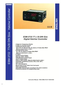
ESM-3722 30.5°C 0.5 OK CE EACESM-3722 77 x 35 DIN Size Digital Hatcher Controller
- 4 Digits for Temperature Display
- 4 Digits for Humidity Display
- Temperature Sensor Input NTC, PTC, PT-100, 0/2..10V, 0/4..20mA or ProNem Mini PMI-P (Must be determined in order.)
- Humidity Sensor Input 0/2..10V, 0/4..20mA or ProNem Mini PMI-P (Must be determined in order.)
- 4 Output Heating Control Output Egg tray rotator Output Humidification Control Output Alarm Control Output
- Relay or SSR Outputs (Must be determined in order.)
- Selectable Temperature Control ( PID or ON / OFF )
- Self-Tune PID
- Set value boundaries
- Manual Start of tray rotator from front panel
- Alarm parametreters
- Adjustable internal buzzer according to the alarm situations
- Password protection for programming mode,
1.Preface
ESM 3722 series Hatcher controllers are designed for controlling hatcher process. Device can be used easily with PID or On-Off control form and manual start of egg tray rotator properties.
1.1 Environmental Ratings

Operating Temperature : -20 to 70 °C

Max. Operating Humidity : 90% Rh (non-condensing)

Altitude : Up to 2000 m.

Forbidden Conditions:
Corrosive atmosphere
Explosive atmosphere
Home applications (The unit is only for industrial applications)
1.2. General Specifications
Standard
230V (%15)50/60Hz\~ ±
Optional Supply Voltage
115 V-(±%15)50/60Hz
24 V(±%15)50/60Hz
24 V(±%15)50/60Hz
10 - 30 V ---
PTC, NTC, PT-100
0/2..10V,0/4..20mA or
ProNem Mini PMI-P
0/2..10V, 0/4..20mA or ProNem Mini PMI-P
ESM-3722
Power Supply Input
Temperature Sensor Input
Humidity Sensor Input
Output
Heating
Output
Humidification
Output
Egg Tray Rotator Output
Output
Alarm
1.3 Installation
A visual inspection of this product for possible damage occurred during shipment is recommended before installation.
It is your responsibility to ensure that qualified mechanical and electrical technicians install this product.
If there is danger of serious accident resulting from a failure or defect in this unit, power off the system and separate the electrical connection of the device from the system.
The unit is normally supplied without a power supply switch or a fuse. Use power switch and fuse as required.
Be sure to use the rated power supply voltage to protect the unit against damage and to prevent failure. Keep the power off until all of the wiring is completed so that electric shock and trouble with the unit can be prevented.
Never attempt to disassemble, modify or repair this unit. Tampering with the unit may results in malfunction, electric shock or fire.
Do not use the unit in combustible or explosive gaseous atmospheres.
During putting equipment in hole on the metal panel while mechanical installation some metal burrs can cause injury on hands, you must be careful.
Montage of the product on a system must be done with it's fixing clamps. Do not do the montage of the device with inappropriate fixing clamp. Be sure that device will not fall while doing the montage.
It is your responsibility if this equipment is used in a manner not specified in this instruction manual.
1.4 Warranty
EMKO Elektronik warrants that the equipment delivered is free from defects in material and workmanship. This warranty is provided for a period of two years. The warranty period starts from the delivery date. This warranty is in force if duty and responsibilities which are determined in warranty document and instruction manual performs by the customer completely.
1.5 Maintenance
Repairs should only be performed by trained and specialized personnel. Cut power to the device before accessing internal parts.
Do not clean the case with hydrocarbon-based solvents (Petrol, Trichlorethylene etc.). Use of these solvents can reduce the mechanical reliability of the device. Use a cloth dampened in ethyl alcohol or water to clean the external plastic case.
1.6 Manufacturer Company
Manufacturer Information:
Emko Elektronik Sanayi ve Ticaret A.Ş.
Demirtaş Organize Sanayi Bölgesi Karanfil Sk. No:6 16369 BURSA/TURKEY
Phone : +90 224 261 1900
Fax : +90 224 261 1912
Repair and maintenance service information:
Emko Elektronik Sanayi ve Ticaret A.Ş.
Demirtaş Organize Sanayi Bölgesi Karanfil Sk. No:6 16369 BURSA/TURKEY
Phone : +90 224 261 1900
Fax : +90 224 261 1912
2. General Description
text_image
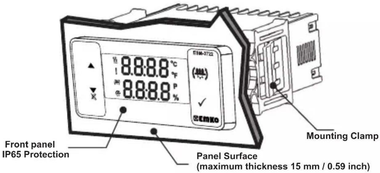
EEM-3722 8.8:8.8 °C 1 °F 8.8:8.8 P 8.8:8.8 % SEM-3722 (###) EMKO Front panel IP65 Protection Panel Surface (maximum thickness 15 mm / 0.59 inch) Mounting Clamp2.1 Front View and Dimensions of ESM-3722 Hatcher Controller
text_image
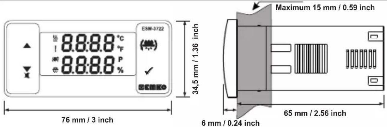
E5M-3722 8.8:8.8 °C 8.8:8.8 °F 8.8:8.8 P 76 mm / 3 inch Maximum 15 mm / 0.59 inch 34,5 mm / 1.36 inch 65 mm / 2.56 inch 6 mm / 0.24 inch2.2 Panel Cut-Out

other
| Dimension | Width (mm) | Height (inch) | | ----------------- | ---------- | ------------- | | Top Left | 110 | 4.33 | | Top Right | 50 | 1.97 | | Middle Right | 29 | 1.14 | | Bottom Right | 71 | 2.79 |2.3 Panel Mounting and Removing
text_image
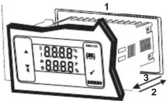
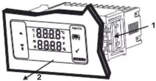
1 8.8.8.8 °C 8.8.8.8 °C 3 21-Before mounting the device in your panel, make sure that the cut-out is of the right size.
2-Insert the device through the cut-out. If the mounting clamps are on the unit, put out them before inserting the unit to the panel.
3- Insert the mounting clamps to the fixing sockets that located left and right sides of device and make the unit completely immobile within the panel
text_image
8.8.8.8°C 8.8.8.8°C 1 21-Pull mounting clamps from left and right fixing sockets.
2-Pull the unit through the front side of the panel

Before starting to remove the unit from panel, power off the unit and the related system.
3. Electrical Wiring Diagram
text_image
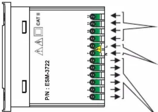
CAT II P/N : ESM-3722 1 2 3 4 5 6 7 8 9 10 11 12 N LTemperature Sensor Input
NTC, PTC, PT-100 or
ProNem Mini PMI-P
Must be determined in order.
Humidity Sensor Input
0/2..10V, 0/4..20mA or
ProNem Mini PMI-P
Must be determined in order.
Power Supply Voltage
230V (9/15) 50/60Hz,
115V ( % 45) 50/60Hz,
24V\~(‰15) 50/60Hz,
24V(15) 50/60Hz,
10...30 V—4.5 W
Must be determined in order.
Relay Outputs
3.1 Supply Voltage Input Connection of the Device
text_image
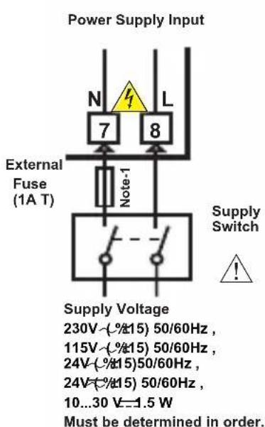
Power Supply Input External Fuse (1A T) Note-1 N L 7 8 Supply Switch ! Supply Voltage 230V~(%15) 50/60Hz , 115V~(%15) 50/60Hz , 24V~(%15)50/60Hz , 24V~(%15) 50/60Hz , 10...30 V=1.5 W Must be determined in order.
Make sure that the power supply voltage is the same indicated on the instrument.
Switch on the power supply only after that all the electrical connections have been completed.
Supply voltage range must be determined in order. While installing the unit, supply voltage range must be controlled and appropriate supply voltage must be applied to the unit.

There is no power supply switch on the device. So a power supply switch must be added to the supply voltage input.
Power switch must be two poled for separating phase and neutral, On/Off condition of power supply switch is very important in electrical connection.
External fuse that on power supply inputs must be on phase connection.
External fuse that on — power supply inputs must be on (+) connection.
Note-1: External Fuse is recommended
3.2 Device Label and Connection Diagram
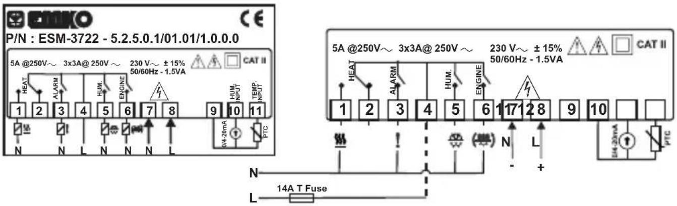
230V\~CONNECTION DIAGRAM
PTC Temperature and 0/4..20mA Humidity Sensor Input connection
text_image
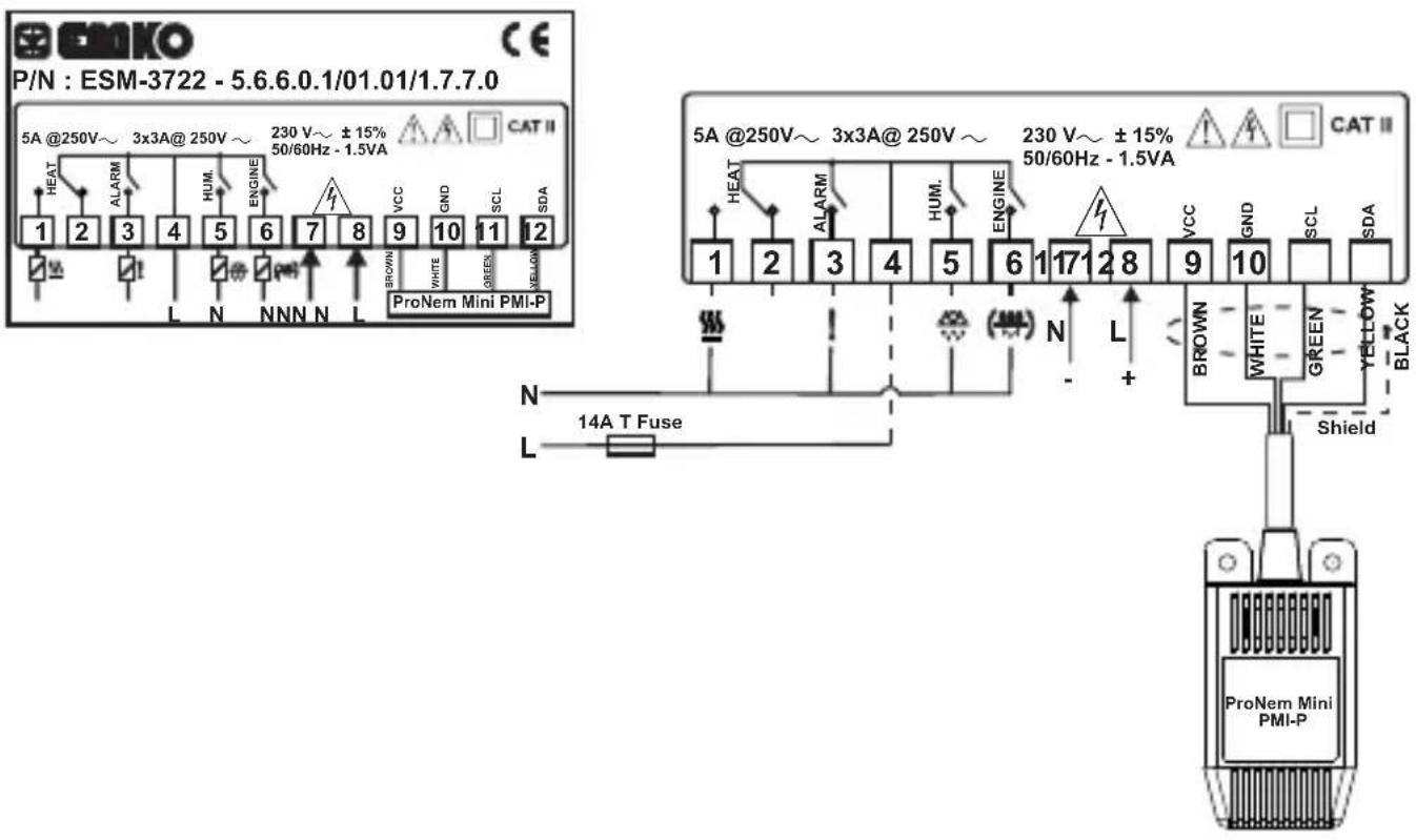
P/N : ESM-3722 - 5.2.5.0.1/01.01/1.0.0.0 5A @250V~ 3x3A@ 250V ~ 230 V~ ±15% 50/60Hz - 1.5VA CAT II HEAT ALARM HUM. ENGINE 1 2 3 4 5 6 7 8 9 10 11 HUM. INPUT TEMP. INPUT PTC N L N N L 0/4-20mA N L 14A T Fuse 5A @250V~ 3x3A@ 250V ~ 230 V~ ±15% 50/60Hz - 1.5VA CAT II HEAT ALARM HUM. ENGINE 1 2 3 4 5 6 7 8 9 10 N L +ProNem Mini PMI-P Temperature and Humidity Sensor Input Connection
text_image
P/N : ESM-3722 - 5.6.6.0.1/01.01/1.7.7.0 5A @250V~ 3x3A@ 250V ~ 230 V~ ±15% 50/60Hz - 1.5VA CAT II HEAT ALARM HUM ENGINE VCC GND SCL SDA 1 2 3 4 5 6 7 8 9 10 11 12 L N NNN N L BROWN WHITE GREEN YELLOW ProNem Mini PMI-P 5A @250V~ 3x3A@ 250V ~ 230 V~ ±15% 50/60Hz - 1.5VA CAT II HEAT ALARM HUM ENGINE VCC GND SCL SDA 1 2 3 4 5 6 1 17 2 8 9 10 N L + BROWN WHITE GREEN YELLOW BLACK 14A T Fuse Shield ProNem Mini PMI-PNote : (Black) pin must be connected to number 10 (GND) of the terminal block.Shield
4.Front Panel Definition and Accessing to the Menus

text_image
1 2 5 6 8.8:8.8 °C ! 8.8:8.8 °F 8.8:8.8 P 9 10 11 12 ESM-3722 (###) ✓ EMIKOBUTTON DEFINITIONS
** In main operation screen, press this button to change display temperature and humidity sensor value.
** It is used to increase the value in the Temperature and Humidity Set screens and Programming mode.
2. Decrement, Silencing Buzzer Button :
** It is used to decrease the value in the Set screen and Programming mode.
** It is used to silence the buzzer.
3. Manual Start of Egg Tray Rotator Operation Button:
**InMthentrainbopterationseased, thethis button pressed engine starts.
engine start will be passive and engine stops.
4. Set Button:
** In the main operation screen; if this button pressed for the first time, Temperature set value will be displayed. Value can be changed using increment and decrement buttons. When Set button is pressed again, value is saved and Humidity set value will be displayed next. Value can be changed using increment and decrement buttons. When Set button pressed again, value is saved and returns back to main operating screen.
** To access the programming screen; in the main operation screen, press and hold this button for 5 seconds.
** It is used to save value in the Set screens (Temperature or Humidity) and programming screen.
LED DEFINITIONS
5. Alarm led :
** It is active when alarm statuses.
6. Heating Output Led :
** This led indicates that heating output is active.
7.Celcius led :
** Indicates that device is in°C mode.
8.Fahrenheit led :
** Indicates that device is in°F mode.
9.EggTray Rotator Output
** This led indicates thatEgg TcayeRotator Output
10. Hountplicating
** This led indicates that Humidity is active.
** Indicates that device is in Humidity Set screen.
12. Program led :
** Indicates that device is in programming mode.
5. Changing and Saving Temperature and Humidity Set Value
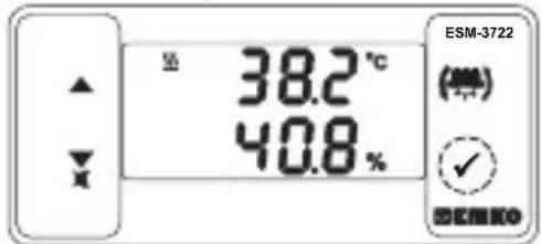
Main Operating Screen
text_image
38.2°C 40.8% ESM-3722 (°C) ✓ ESEMWhen SET button pressed "S" led will be active and temperature set value will be displayed.
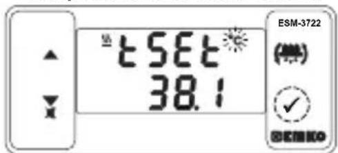
Temperature Set Value Screen
text_image
tSET 38.1 ESM-3722 (●) ✓ OK/RENOWhen SET button pressed temperature set value can be saved.
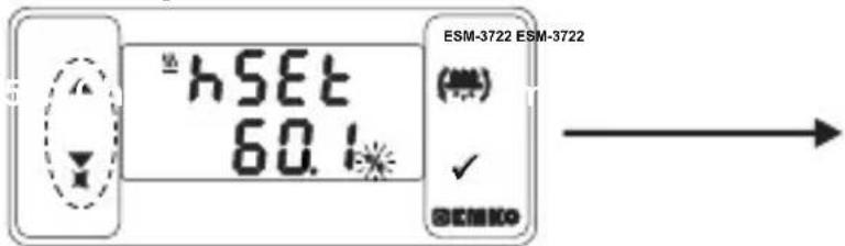
Humidity Set Value Screen
text_image
hSET 60.1 ESM-3722 ESM-3722 (●) ✓ SEMKOHumidity set value can be changed with increment and decrement buttons.
Temperature Set Value Screen
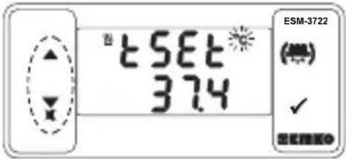
text_image
tSET 374 ESM-3722 (000) ✓ BENKOTemperature set value can be changed with increment and decrement buttons.
Humidity Set Value Screen
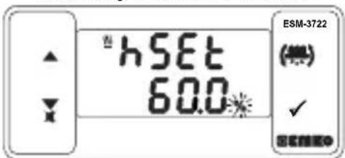
text_image
hSET 60.0 ESM-3722 (★) ✓Goes Humidity SET value screen.
Humidity Set Value Screen
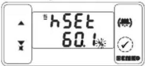
text_image
hSET 60.1 (無) OKWhen SET button pressed Humidity set value can be saved. Goes back to main operation screen.
Temperature set value parameter (Default =37.7 °C)
Temperature set value, can be programmed between minimum temperature set value E.SUL and maximum temperature set value E.SUR.
Humidity set value parameter (Default = 60%)
Humidity set value, can be programmed between minimum Humidity set value hSUL and maximum temperature set value hSUV.

If no operation is performed in Humidity set value changing mode and temperature set value changing mode for 20 seconds, device turns to main operation screen automatically.
5.1 Programming Mode Parameter List

Temperature Unit Selection Parameter (Default = 0)
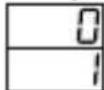
°C selected. °F selected.

Decimal Seperator Enabling Parameter (Default = 0)
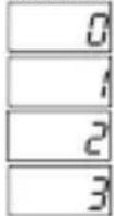
None. Only Temperature parameters with decimal separator.
Only Humidity parameters with decimal separator.
Only Temperature and Humidity parameters with decimal separator.
Note: When value of C-F or Pnt parameters are changed, the values of ESET, hSE, ESUL, ESUN, EoFT, ERSE, hALh, hAUL, tRUN, hSET, hHST, hSUL, hSUh, hoFT, hRST, hALh, hAUL and hRUN parameters should be changed accordingly.
5.1 Programming Mode Parameter List
Note: ESSL, EoPL and Elol parameters are shown, if the Temperature sensor analogue input type (0/2..10V or 0/4..20mA) is selected.
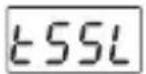
Temperature Sensor Scale Selection Parameter (Default = 0)
Analogue (T input range is determined with this parameter.emperature)

text_image
0..10V (1)(2) veya 0..20mA =---- 2..10V veya 4..20mA =_(2)(1)
TemperatureSensor Scale Low Limit Parameter : ( Default = 0 )
It can be adjusted from -1999 to EUPL -1). At this value analogue input becomes;

text_image
If kSSL =0, according to the device type 0V (1) or 0mA (2) If kSSL =1, according to the device type 2V (1) or 4mA (2)
Temperature Sensor Scale High Limit Parameter : ( Default = 100 )
It can be adjusted from ( 1 +1) to 9999. At this value analogue input becomes; According to the device type 10V (1)--- or 20mA (2)---
Note : tLol, tupl parameters are shown, if the Temperature sensor analogue input type is selected.
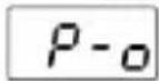
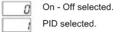
Temperature Control Selection Parameter On/Off or PID (Default = 0)
text_image
On - Off selected. PID selected.Note: If this parameter is select 0, PID parameters ( , , , , ) will be not observed. If this parameter select 1 parameter will be not observed.
Self Tune (Step Response Tuning) Selection Parameter (Default = □)

text_image
no Device does not do ( ) operation.Step Response Tuning YES Device does operation.
PID - Proportional Control Parameter (Default =1.0)
This parameter value can be adjusted from 0.1 to 100.0
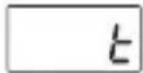
PID - Integral Parameter( Default = 300 )
This parameter value can be adjusted from 0 to 3600.
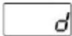
PID - Derivative Parameter (Default = 60)
This parameter value can be adjusted from 0 to 999.9
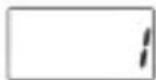
PID -Period Time Parameter (Default = 1)
This parameter value can be adjusted from 1 to 150 second.
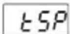
PID -Temperature Protection Parameter (Default = OFF)
When PID operation is performed, the heating output is switched off if the temperature value goes above the value defined by tSP . When the value is 0 or 0.0, if the value decrease button is pressed, oFF appears and this function is disabled. From 1 to 10°C for NTC, PTC, PT-100 (0°C, 100°C), From 1 to 18°F for NTC, PTC, PT-100 (32°F, 212°F), From 0.1 to 10.0°C for NTC, PTC, PT-100 (0.0°C, 100.0°C), From 0.1 to 18.0°F for NTC, PTC, PT-100 (32.0°F, 212.0°F), From 1 to 10°C for ProNem Mini PMI-P (-20°C, 80°C), From 1 to 18°F for ProNem Mini PMI-P (-4°F, 176°F), From 0.1 to 10.0°C for ProNem Mini PMI-P (-20.0°C, 80.0°C), From 0.1 to 18.0°F for ProNem Mini PMI-P (-4.0°F, 176.0°F).
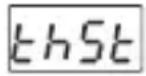
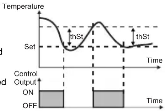
Hysteresis Parameter for Temperature (Default = 0.1 °C)
From 1 to 10°C for NTC, PTC, PT-100 (0°C, 100°C), From 1 to 18°F for NTC, PTC, PT-100 (32°F, 212°F), From 0.1 to 10.0°C for NTC, PTC, PT-100 (0.0°C, 100.0°C), From 0.1 to 18.0°F for NTC, PTC, PT-100 (32.0°F, 212.0°F), From 1 to 10°C for ProNem Mini PMI-P (-20°C, 80°C), From 1 to 18°F for ProNem Mini PMI-P (-4°F, 176°F), From 0.1 to 10.0°C for ProNem Mini PMI-P (-20.0°C, 80.0°C), From 0.1 to 18.0°F for ProNem Mini PMI-P (-4.0°F, 176.0°F).
In ON/OFF control algorithm, temperature value is tried to keep equal to set value by opening or closing the last control element. ON/OFF controlled system, temperature value oscillates continuously. Temperature value's oscillation period or amplitude around set value changes according to controlled system. For reducing oscillation period of temperature value, a threshold zone is formed below or around set value and this zone is named hysteresis.
line
| Time | Temperature | |------|-------------| | 0 | 1.0 | | 1 | 0.5 | | 2 | 0.8 | | 3 | 1.0 | | 4 | 0.5 | | 5 | 0.8 |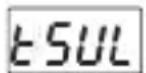
Minimum Temperature Set Value Parameter (Default = 10.0°C)
Temperature set value can not be lower than this value. This parameter value can be adjusted from minimum value of device scale to maximum temperature set value parameter E Suh
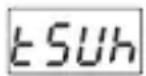
Maximum Temperature Set Value Parameter (Default = 40.0 °C)
Temperature set value can not be greater than this value. This parameter value can be adjusted from minimum temperature set value parameter to maximum value of the device scale.
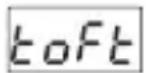
Temperature Sensor Offset Parameter (Default = 0)
From -10 to 10°C, NTC,PTC, PT-100 (0°C, 100°C) From -18 to 18°F, NTC,PTC, PT-100 (32°F, 212°F) From -10.0 to 10.0°C, NTC,PTC, PT-100 (0.0°C,100.0°C) From -18.0 to 18.0°F NTC, PTC, PT-100 (32.0°F,212.0°F) From -10 to 10°C,ProNem Mini PMI-P (-20°C, 80°C) From -18 to 18°F,ProNem Mini PMI-P (-4°F, 176°F) From -10.0 to 10.0°C, ProNem Mini PMI-P (-20.0°C, 80.0°C) From -18.0 to 18.0°F, ProNem Mini PMI-P (-4.0°F,176.0°F)
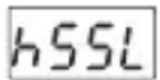
Humidity Sensor Scale Selection Parameter (Default = 0)
Analogue input range is determined with this parameter.

text_image
0..10V (1)(2) 0..20mA ===or === 2..10V 4..20mA ===or (2)(1)Note : kSSL parameter ProNem Mini PMP type device are not observed.
Hysteresis Parameter for Humidity (Default = 1)
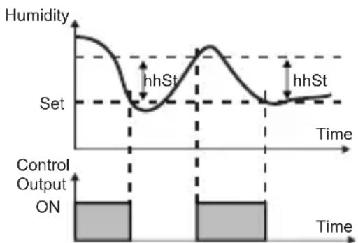
From 1 to 10 for Humidity Sensor (0%RH, 100%RH) From 0.1 to 10.0 for Humidity Sensor (0.0%RH, 100.0%RH)
In ON/OFF control algorithm, Humidity value is tried to keep equal to set value by opening or closing the last control element. ON/OFF controlled system, temperature value oscillates continuously. Temperature value's oscillation period or amplitude around set value changes according to controlled system. For reducing oscillation period of temperature value, a threshold zone is formed below or around set value
line
| Time | Humidity | |------|----------| | 0 | High | | 1 | Low | | 2 | High | | 3 | Low |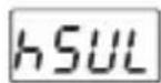
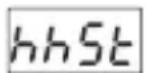
Minimum Humidity Set Value Parameter (Default = Minimum Value of Device Scale) Humidity set value can not be lower than this value. This parameter value can be adjusted from minimum value of device scale to maximum Hemvalite parameter
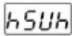
Maximum Humidity Set Value Parameter (Default = Maximum Value of Device Scale) Humidity set value can not be greater than this value. This parameter value can be adjusted from minimum humidity set value parameter to maximum value of the device scale.
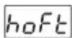
Humidity Sensor Offset Parameter (Default = 0.0)
From -10 to 10 for Humidity Sensor (0%RH, 100%RH)
From -10.0 to 10.0 for Humidity Sensor (0.0%RH, 100.0%RH)
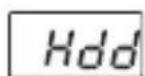
Humidity Decrease Amount Parameter for Door Opened Control (Default = )
To detect that the door is opened, the humidity must be reduced in the amount defined by the parameter in the time defined by the parameter. From -5 to 20 for Humidity Sensor (0%RH, 100%RH) From 5.0 to 20.0 for Humidity Sensor (0.0%RH, 100.0%RH) If the value decrease button is pressed while the parameter value is 5 or 5.0, is displayed and this function is disabled and the parameters and are not observed.
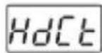
Humidity Decrease Amount Control Time Parameter for Door Opened Control (Default = 20)
To detect that the door is opened, the humidity must be reduced in the amount defined by the Hold parameter in the time defined by the Hold parameter.
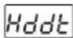
Off Time of Humidity Output Parameter for Door Opened Control (Default = 60)
When it is detected that the door is opened, the humidity output is switched off for the time defined by the Hddt parameter. This parameter can be between 10 seconds and 999 seconds.

(1) It is valid, if the device type 0/2...10V ---Humidity Sensor Input.
(2) It is valid, if the device type 0/4...20mA === Humidity Sensor Input.
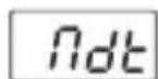
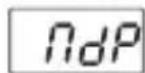
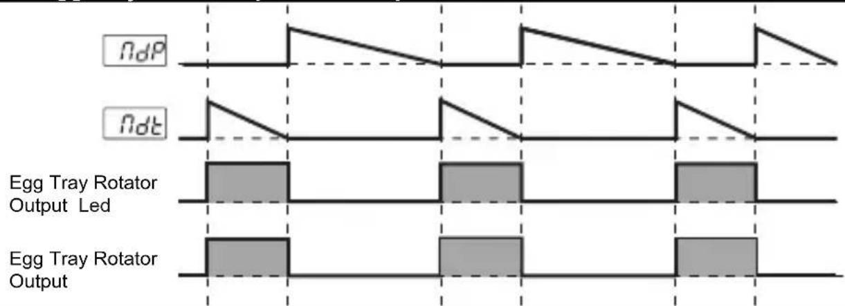
Time of Automatic Egg Tray Rotator (Default = 00:00)
This parameter value can be adjusted from 00:00 to 99:59 minute/second.
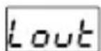
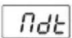
Repeat cycle of Automatic Egg Tray Rotator (Default = 00:00)
This parameter value can be adjusted from 00:00 to 24:00 hour/minute.
Alarm Output Function Selection Parameter (Default = 0)

Alarm is inactive.

Alarm-Temperature sensor failures.

Alarm-Humidity sensor failures.
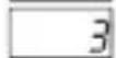
Alarm-Temperature or Temperature sensor failures.

Alarm-Humidity or Humidity sensor failures.

Alarm-Temperature sensor failures or Humidity sensor failures.

Alarm-Temperature or Humidity or Temperature sensor failures or Humidity sensor failures.
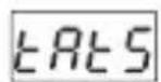
Note : if Lout parameter value is 3 or 6 ERES, EASE, ERLH, EROL, EROLH, ERel or kRPd parameters are observed.
Note : if parameter value is 4 or 6 , , ,h, , , or parameters are observed.
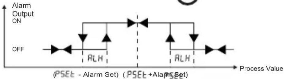
Temperature Alarm Function Selection Parameter (Default = 1)
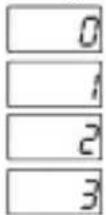
Process High alarm selected.
Process Low alarm selected.
Deviation Band alarm selected.
Deviation Range alarm selected.
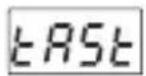
Temperature Alarm Set Parameter (Default = 50.0 °C)
This parameter value can be programmed between temperature minimum alarm set parameter and temperature alarm set maximum parameter.
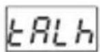
Temperature Alarm HySteresist(Default = 0)
This parameter value can be adjusted from 0 to %50 of the device scale.
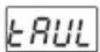
Alarm Set Minimum Parameter (Default = Minimum Value of Device Scale)
if temperature alarm is active, this parameter value can be adjusted from minimum value of device scale to temperature alarm set maximum parameter value.
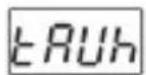
Alarm Set Maximum Parameter (Default = Maximum Value of Device Scale)
if temperature alarm is active, this parameter value can be adjusted from temperature alarm set value parameter ERUL to maximum value of the device scale.
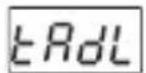
Temperature Alarm On Delay Time Parameter( Default = 0)
Temperature Alarm On Delay Time can be defined with this parameter. It can be adjusted from 0 to 99 minutes.
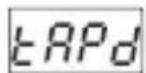
Temperature Alarm Delay After Power On Parameter (Default = 0)
When power is first applied to the device, this time delay must be expired for activation of temperature alarm. It can be adjusted from 0 to 99 minutes.
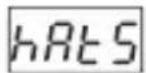
Humidity Alarm Function Selection Parameter (Default = 0)
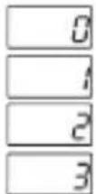
Process High alarm selected.
Process Low alarm selected.
Deviation Band alarm selected.
Deviation Range alarm selected.
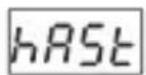
Humidity Alarm Set Parameter (Default = 50)
This parameter value can be programmed between humidity minimum alarm set hRut parameter and humidity alarm set maximum hRuh parameter.

Humidity Alarm HySteresise(Default = 0)
This parameter value can be adjusted from 0 to \%50 of the device scale.
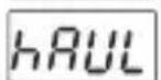
Humidity setMinimum Parameter(Default = Minimum Value of Device Scale)
if humidity alarm is active, this parameter value can be adjusted from minimum value of device scale to humidity alarm set maximum parameter value.
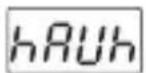
Humidity Alert Maximum Parameter(Default = Maximum Value of Device Scale)
if humidity alarm is active, this parameter value can be adjusted from humidity alarm set minimum parameter [hRUL] to maximum value of the device scale.
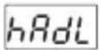
Humidity (Default On Delay Time Parameter
Humidity Alarm On Delay Time can be defined with this parameter. It can be adjusted from 0 to 99 minutes.
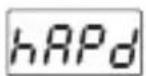
Humidity (Default) After Power On Parameter
When power is first applied to the device, this time delay must be expired for activation of Humidity alarm. It can be adjusted from 0 to 99 minutes.
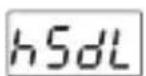
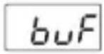
Humidity Out Stop-Start and Start-Stop Delay Parameter (Default=2)
This time must pass before the humidity out is turned on again after it is turned off, or turned off again after it is turned on. It can be adjusted from 0 to 20 minutes.
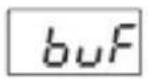
Buzzer Function Selection Parameter( Default = 0 )
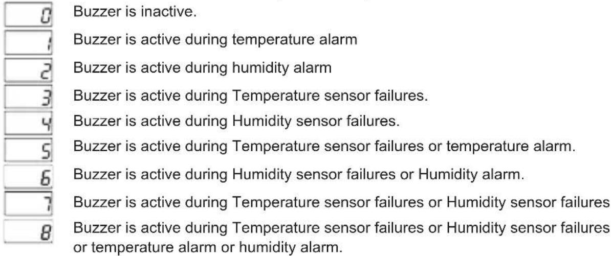
text_image
0 Buzzer is inactive. 1 Buzzer is active during temperature alarm 2 Buzzer is active during humidity alarm 3 Buzzer is active during Temperature sensor failures. 4 Buzzer is active during Humidity sensor failures. 5 Buzzer is active during Temperature sensor failures or temperature alarm. 6 Buzzer is active during Humidity sensor failures or Humidity alarm. 7 Buzzer is active during Temperature sensor failures or Humidity sensor failures 8 Buzzer is active during Temperature sensor failures or Humidity sensor failures or temperature alarm or humidity alarm.
Buzzer Active Time (Default = \_\_\_\_ )
If buzzer function selection parameter value b_uF = 0 , this parameter is not observed. Buzzer active time can be defined with this parameter. It can be adjusted from 1 to 99 minutes. When this parameter is 1, if decrement button is pressed, ---- is observed. In this condition buzzer is active till buzzer silence button is pressed.
Button Protection Parameter (Default = 0)
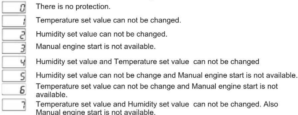
text_image
There is no protection. Temperature set value can not be changed. Humidity set value can not be changed. Manual engine start is not available. Humidity set value and Temperature set value can not be changed Humidity set value can not be change and Manual engine start is not available. Temperature set value can not be change and Manual engine start is not available. Temperature set value and Humidity set value can not be changed. Also Manual engine start is not available.
Programming Mode Accessing Password (Default = 0)
It is used for accessing to programming mode. It can be adjusted from 0 to 9999. If it is 0, password is not entered for accessing to the parameters. When the password screen is not set as "12", if the user enters '12' in password screen and hhst parameters are accessed and they can changed.
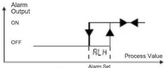
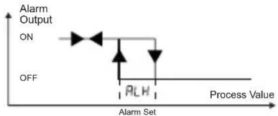
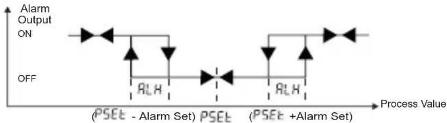
5.2 Alarm Output Graphics of ESM-3722
Process High Alarm
flowchart
graph TD
    A["ON"] --> B["RLH"]
    C["OFF"] --> D["Process Value"]
    style A fill:#f9f,stroke:#333
    style B fill:#ccf,stroke:#333
    style C fill:#cfc,stroke:#333
    style D fill:#fcc,stroke:#333
Process Low Alarm
line
| Process Value | Alarm Output | | ------------- | ------------ | | ON | ON | | PLH | OFF |Deviation Band Alarm
line
| Process Value | Alarm Output ON | Alarm Output OFF | | ------------- | --------------- | ---------------- | | (PSET - Alarm Set) | High | Low | | PSET | Low | High | | (PSET + Alarm Set) | High | Low |Deviation Range Alarm

PSCT ≡ Process Set Value (Temperature or Humidity)
line
| Process Value | Alarm Output ON | | ------------- | --------------- | | Low | OFF | | High | RLH |5.3 Egg Tray Rotator Operation Graphics of ESM-3722
line
| Signal | Time (s) | |--------|----------| | ndP | 0 | | ndt | 0 | | Egg Tray Rotator Output Led | 1 | | Egg Tray Rotator Output | 2 |5.4 Failure Messages in ESM 3722 Hatcher Controller
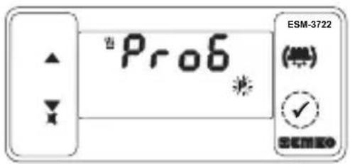
1-5br 1 Screen Blinking Temperature Sensor failure. Sensor connection is wrong or there is no sensor connection. While this message shown on this display, if buzzer function selection buf is 3, 5, 7 or 8 internal buzzer starts to operate.
2 Screen Blinking H Sensor formidity. Sensor connection is wrong or there is no sensor connection. While this message shown on this display, if buzzer function selection is 4, 6,7 or 8 internal buzzer starts to operate.
3- In main operating screen if the upper display is blinking, it means that temperature alarm exits and alarm output is active. If buzzer function selection 5UF is 1, 5 or 8 internal buzzer starts to operate.
4- In main operating screen if the lower display is blinking, it means that humidity alarm exits and alarm output is active. If buzzer function selection is 2, 6 or 8 internal buzzer starts to operate.
5- Self Tune temperature error. Appears on the main screen.this fault occurs when the temperature read from the sensor is closer to the Process Set value than 5% of the scale(5 °C for the ProNem Mini PMI-P sensor). Self tune operation is not allowed.
5.5 Entering To The Programming Mode, Changing and Saving Parameter
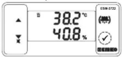
Main Operation Screen
text_image
38.2°C 40.8% ESM-3722 (°) ESEMWhen SET button is pressed for 3 seconds, "P" led turn. If programming mode entering password is different from 0, programming mode entering screen P-6 will be observed. Note1: If programming mode accessing password is 0, Temperature Unit screen [C-F] is observed instead of programming screen [Pr-S]

text_image
ESM-3722 (###) SEM#0Programming Mode Entering Screen
Press SET button for accessing to the password entering
Password Entering Screen
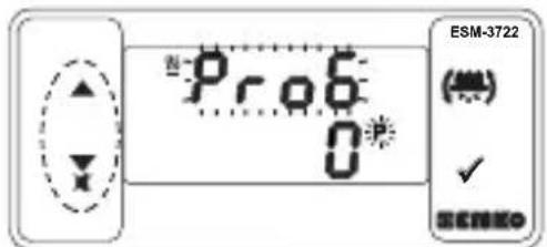
text_image
ESM-3722 (★) ✓ ESEM0Enter programming mode accessing password with increment and decrement buttons.

Password Entering Screen
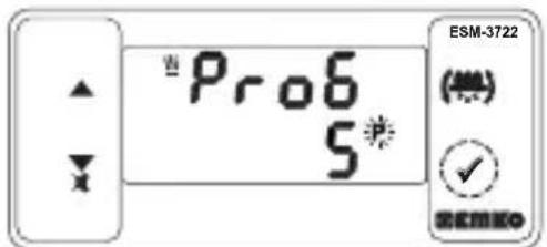
text_image
ESM-3722 (※) ✓Press SET/OK button for entering the password.
Note2: If programming mode accessing password is 0, only three parameters are accessible, and the parameter values can be changed.
Programming Screen
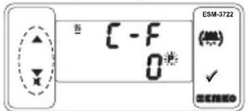
text_image
C - F 0*Press SET button for accessing to the parameter value. Press increment button for accessing to the next parameter, press decrement button for accessing to the previous parameter.

Temperature Unit Selection Parameter Value
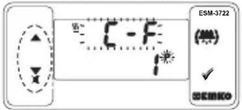
text_image
ESM-3722 (###) ✓ DEEMKOChange the value with increment and decrement buttons.
Temperature Unit Selection
Parameter Value
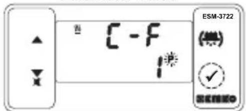
text_image
ESM-3722 C - F 1Press set button for saving the parameter.

Decimal Separator Enabling Selection Screen
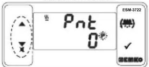
text_image
ESM-3722 (※) ✓ OK/OKPress increment button for accessing to the next parameter, press decrement button for accessing to the previous parameter.

If no operation is performed in programming mode for 20 seconds, device turns to main operation screen automatically.
6. Manual Start of Egg Tray Rotator Operation with Engine Button
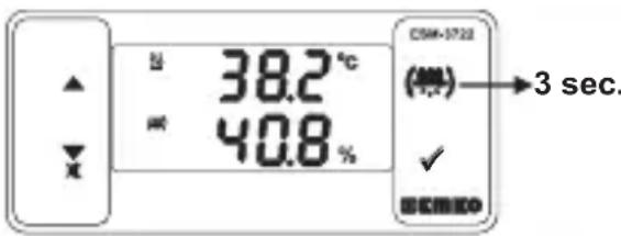
text_image
U 38.2 °C W 40.8 % CSM-1722 (℃) → 3 sec. ✓ ECMEOWhile button protection parameter value is Prb 0,1,2 or 4 in main operation screen if engine button is pressed, manual engine start will be active. When the button is released the engine start will be passive and engine stops.
7. Self Tune Metod
Self Tune method is used for determining PID parameters used by the device.
Starting Self Tune (Step Response Tuning) Operation by the user :
- Adjust temperature control on/off or PID parameter
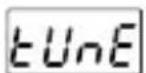
( P - o = 1) - Adjust self tune selection parameter ( EUnE = YES )
- In the main screen “Tune” and Temperature value are should alternately.
If Self Tune operation is finished without any problem, the device saves the new PID coefficients to memory and continue to run. Parameter is adjusted 0 automatically.
NOT: The temperature value read from the sensor must be less than 5% of the process set value in order to start the self tune operation ( 5^ C for the ProNem Mini PMI-P sensor).
Cancelling Self Tune(Step Response Tuning) operation :
1 - If sensor breaks;
2 - If auto tune operation can not be completed in 8 hours ;
3 - If user adjusts tune parameter no ;
4- During self tune operation if the user changes the temperature control from pid to on/off;
5 - If process set value is changed while self tune operation is being performed;
Self tune is canceled. "Tune" is not displayed. Then, without doing any changes in PID parameters, device continues to run with previous PID parameters.
8. Specifications
| Device Type | : Hatcher Controller |
| Housing&Mounting | : 76 mm x 34.5 mm x71 mm Plastic housing for panelPanel cut out is 71 x 29 mm. |
| Protection Clas | : Ip65 at front, Ip20 at rear. |
| Weight | : Approximately 0.2 Kg |
| Environmental Ratings | : Standart, indoor at an altitude of less than 2000 meters withnone condensing humidity. |
| Storage / Operating Temperature | :-30°C to +80 C / -20 C to +70 C |
| Storage / Operating Humidity | : 90 % max. (None condensing) |
| Installation : Fixed installation | |
| Overvoltage Category : II. | |
| Pollution Degree : II, office or workplace, none conductive pollution | |
| Operating Conditions : Continuous | |
| Supply Voltage and Power | : 230V (~%±15) 50/60Hz - 1.5VA: 115V (~%±15) 50/60Hz - 1.5VA: 24V (~%±15) 50/60Hz - 1.5VA: 24V (~%±15) 50/60Hz - 1.5VA: 10 -30V--- 1.5W |
| Temperature Sensor Input | : NTC, PTC, PT-100,0/2..10V---,0/4..20mA--- orProNem Mini PMI-P |
8. Specifications
| NTC input type | : NTC (10 kΩ @25 °C) |
| PTC input type | : PTC (1000 Ω @25 °C) |
| Termoresistance input type | : PT-100 IEC751 (ITS90) |
| Humidity input type | : 0/2..10V---,0/4..20mA--- or ProNem Mini PMI-P |
| Accuracy | : ± 1 % of full scale |
| Sensor Break Protection | : Upscale |
| Control Form | : PID or ON / OFF |
| Relay Outputs | : 5 A@250 V ~ at Resistive Load (Heating Output) |
| : 3 A@250 V ~ at Resistive Load ( Humidificating, Alarm and Egg tray rotator Output | |
| Optional SSR Driver Output | : Maximum 30mA, Maximum 15V |
| Temperature Display | : 8 mm Red 4 digit LED Display |
| Humidity Display | : 8 mm Green 4 digit LED Display |
| LED Displays | : P (Green),%(Green),°C (Red),°F(Red), Alarm (Red), Humidifier Output (Red), Egg tray rotator Output (Red) Heating Output (Red), |
| Internal Buzzer | : ≥83dB |
| Upprovals | : C€,EHE |
10. Other Informations
| ESM-3722(77x35 DIN Size) | A | B | C | D | E | F | G | HI | I | U | V | W | Z | ||||||
| Power Supply VoltageA | |||||||||||||||||||
| 2 | 24V~ (±%15) 50/60Hz - 1.5VA | ||||||||||||||||||
| 3 | 24V~ (±%15) 50/60Hz - 1.5VA | ||||||||||||||||||
| 4 | 115V~ (±%15) 50/60Hz - 1.5VA | ||||||||||||||||||
| 5 | 230V~ (±%15) 50/60Hz - 1.5VA | ||||||||||||||||||
| 8 | 10 - 30 V --- 1.5W | ||||||||||||||||||
| B | Temperature Sensor Input | Scale(°C/°F) | |||||||||||||||||
| 1 | PT 100, IEC751(ITS90) | 0°C/32°F ;100°C/212°F | |||||||||||||||||
| 2 | PTC (Not-1) | 0°C/32°F ;100°C/212°F | |||||||||||||||||
| 3 | NTC (Not-1) | 0°C/32°F ;100°C/212°F | |||||||||||||||||
| 4 | 0/2..10Vdc Voltage Input | User defined | |||||||||||||||||
| 5 | 0/4..20mA Current Input | User defined | |||||||||||||||||
| 6 | ProNem Mini PMI-P | -20°C/-4°F ; 80°C/176°F | |||||||||||||||||
| C | Humidity Sensor Input | Scale (%) | |||||||||||||||||
| 4 | 0/2..10Vdc Voltage Input | 0% - 100% | |||||||||||||||||
| 5 | 0/4..20mA Current Input | 0% - 100% | |||||||||||||||||
| 6 | ProNem Mini PMI-P | 0% - 100% | |||||||||||||||||
| E | Heating Output |
| 1 | Relay Output (5 A@250 V~,at Resistive Load 1NC,1 NO) |
| 2 | SSR Drive Output (Maximum 30mA,Maximum 15V) |
| FC | Humidifier Output |
| 01 | Relay Output (3A@250 V~,at Resistive Load,1 NO) |
| HI | Egg Try Rotator Output |
| 01 | Relay Output (3A@250 V~,at Resistive Load,1 NO) |
| U | Alarm Output |
| 1 | Relay Output (3A@250 V~,at Resistive Load,1 NO) |
| V | Temp.Sensor which is given with ESM-3722 |
| 0 | None |
| 1 | PTC-M6L40.K1.5 (PTC Air Probe 1.5 m silicon cable) |
| 2 | PTCS-M6L30.K1.5.1/8"(PTC Liquid Probe with 1.5 m silicon cable) |
| 3 | NTC-M5L20.K1.5 (NTC Probe thermoplastic moulded with 1.5m cable for cooling application) |
| 4 | NTC-M6L50.K1.5 (NTC Probe stainless steel housing with 1.5m cable for cooling application) |
| 7 | ProNem Mini PMI-P.PT (Pt100 Temperature and Humidity Sensor with 2.5 mt cable) |
| 9 | Customer |
All order information of ESM-3722 Hatcher Controller are given on the table at above. User may form appropriate device configuration from information and codes that at the table and convert it to the ordering codes. Firstly, supply voltage then other specifications must be determined. Please fill the order code blanks according to your needs. Please contact us, if your needs are out of the standards.
Note-1: If input type is selected PTC or NTC (B = 2, 3), Temperature sensor is given with the device. For this reason, if input type is selected as PTC, sensor type (V = 0, 1 or 2) or if input type is selected as NTC, sensor type (V = 0, 3 or 4) must be declared in ordering information.

text_image
Emko Thank you very much for your preference to use Emko Elektronik products, please visit our Your Technology Partner web page to download detailed user manual. www.emkoelektronik.com.tr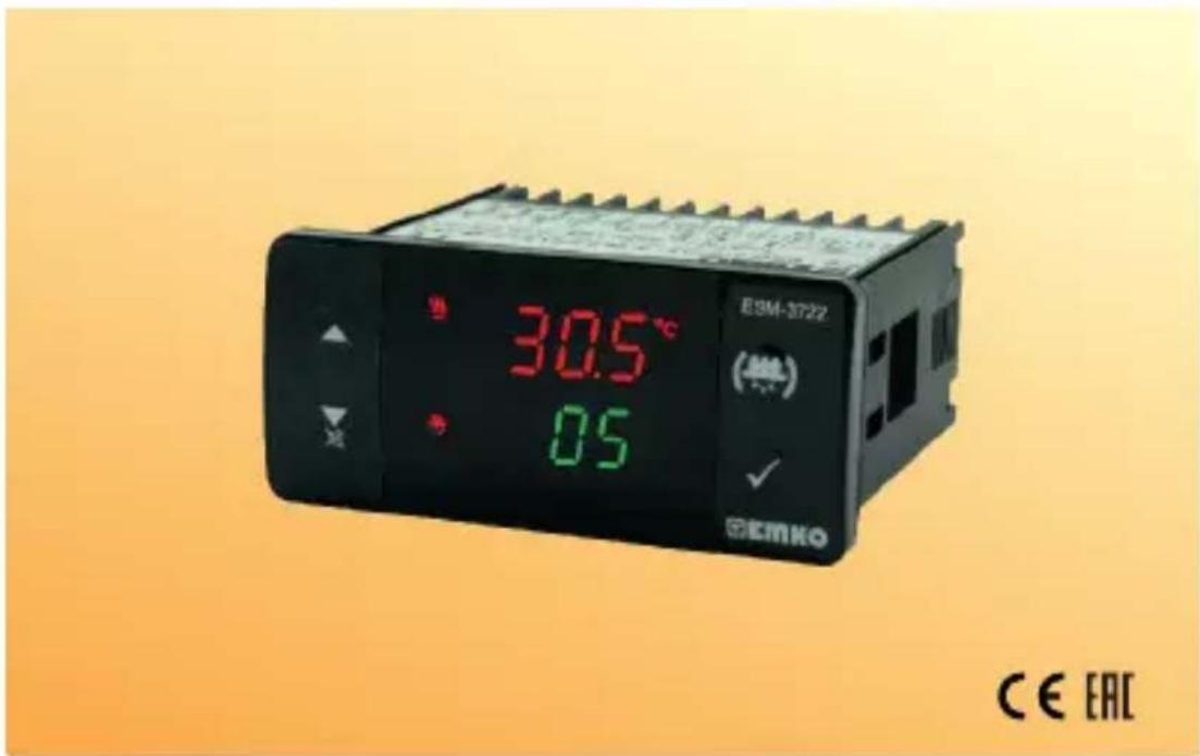
text_image
30.5°C 0.5 E3M-3722 (###) CE EACtext_image
1 8.8:8.8° 8.8:8.8° (等) ✓ 3 2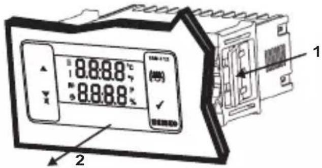
text_image
8.8.8.8 °C 8.8.8.8 °C (40) ✓ 1 2text_image
hSET 60.1(1) It is valid, if the device type 0/2...10V --- Humidity Sensor Input.
(2) It is valid, if the device type 0/4...20mA — Humidity Sensor Input.
line
| Phase | Value | | ------------- | ----- | | EIN | Start | | RLH | End |text_image
38.2°C 40.8% CWH-1723 (℃) → 3 sec. ✓ ECNICO7. Self-Tune-Methode
$$ (\boxed {P - o} = 1) $$
text_image
hSET 60.1line
| Phase | Temperature | | ----------- | ----------- | | Consigne | Low | | thSt | High |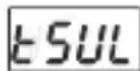
This time must pass before the humidity out is turned on again after it is turned off, or turned off again after it is turned on. It can be adjusted from 0 to 20 minutes.
text_image
hSET 60.1line
| Event | Value | |-------|-------| | ON | ON | | RL H | RL H | | OFF | Off |other
| Signal | Event Description | |--------|--------------------------------------| | ηdP | High phase, Low phase, High phase, Low phase | | ηdt | High phase, Low phase, High phase, Low phase |text_image
ESM-3722 (★) ✓ OK/OKtext_image
hSET 60.1other
| Signal | Time Segment 1 | Time Segment 2 | Time Segment 3 | |--------|----------------|----------------|----------------| | ΠdP | High | Low | High | | Πdt | Low | High | Low | |atore | Medium | Medium | Medium | | uova | Low | High | Low | | e | Low | Low | High | | uova | Low | Low | Low |text_image
38.2°C 40.8% 3 sec.: NTC, PTC, PT-100,0/2..10VZ,0/4..20mA= o
ProNem Mini PMI-P