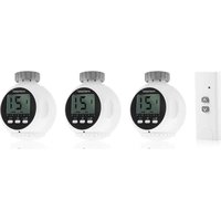
SHS-53002-EU - Thermostat SMARTWARES - Free user manual and instructions
Find the device manual for free SHS-53002-EU SMARTWARES in PDF.


| Product type | Smart radiator valve (wireless thermostat) |
| Brand | Smartwares |
| Model | SHS-53002-EU |
| Valve power supply | 2 AA 1.5 V batteries (not included) |
| Remote control power supply | 1 A23 12 V battery (not included) |
| Valve operating voltage | 3 V DC |
| Temperature measurement range | 0 °C to 29.5 °C |
| Temperature setting range | 5 °C to 28 °C |
| Measurement accuracy | ±0.5 °C |
| Adjustment step | 1 °C or 2 °C adjustable |
| Measurement cycle | 2 minutes |
| Operating ambient temperature | 0 °C to 35 °C |
| Relative humidity | 5% to 90% |
| Radio frequency | 433.92 MHz |
| Maximum radio range | 30 m |
| Maximum consumption | 100 mA |
| Standby consumption | 500 µA max |
| Programming | Weekly and holiday mode |
| Control modes | Manual, remote control, HomeWizard app |
| Safety functions | Child lock, open window detection, temperature correction |
| Valve compatibility | Standard and Danfoss (RA, RAV, RAVL) |
| Maintenance | Clean with a dry cloth, check the retaining ring monthly |
| Maximum number of linked devices | 3 |
| Warranty | 2 years |
Frequently Asked Questions - SHS-53002-EU SMARTWARES
User questions about SHS-53002-EU SMARTWARES
0 question about this device. Answer the ones you know or ask your own.
Ask a new question about this device
Download the instructions for your Thermostat in PDF format for free! Find your manual SHS-53002-EU - SMARTWARES and take your electronic device back in hand. On this page are published all the documents necessary for the use of your device. SHS-53002-EU by SMARTWARES.
USER MANUAL SHS-53002-EU SMARTWARES
wireless climate control
NL GEBRUIKERSHANDLEIDING 2
EN USER MANUAL 17
FR MANUEL D'UTILISATION 32
text_image
Technical diagram of a mechanical component with numbered parts labeled 1 to 44.3 Overzicht display
natural_image
Three-step diagram showing a robotic arm with blue arrows indicating motion (no text or symbols)natural_image
Illustration of three different medical or laboratory equipment setups with no visible text or symbolstext_image
Danfoss RAVL ring RA E F D RAV E E RAVL DDanfoss RAVL ring
2.1 Description of product....18
2.2 Environmental influences .... 18
3 Precautions and safety instructions....18
4 Composition of product 19
4.1 Main components....19
4.2 Component parts 20
4.3 Overview display....21
5 First use 21
5.1 Placing the batteries....21
5.2 Set the date and time....21
6 Assembly and installation....22
6.1 Preparation for assembly....22
6.2 Assembly on a standard valve....22
6.3 Assembly on a Danfoss valve 23
6.4 Reinstallation of the smart thermostat head 24
7 Operation 24
7.1 Manual operation of the heating control set 24
7.1.1 View the current temperature....24
7.1.2 De actuele temperatuur bekijken 24
7.1.3 Setting a high and low temperature....25
7.1.4 Setting Programmes 25
7.1.5 Switching child lock system on or off....26
7.1.6 Setting temperature protection in case of ventilation 26
7.1.7 Adjusting the date and time....27
7.1.8 Set a temperature correction....27
7.1.9 Resetting to factory settings....28
7.2 Operating the heating control set with remote control 28
7.2.1 Setting a high or a low temperature....28
7.2.2 Operate the smart thermostat head with a remote control....29
7.2.3 Disconnect all remote control devices via the smart thermostat head 29
7.3 Operating the heating control set with Homewizard....29
7.3.1 How do I add the smart thermostat head to the HomeWizard app?......29
7.3.2 How do I set the temperature? 30
7.3.3 How do I enable or disable the smart thermostat head? 30
7.4 Other HomeWizard applications....30
8 Maintenance....30
9 Failures....31
10 Warranty....3
II Technical specifications....31
I Foreword
Thank you for purchasing the wireless heating control set. This manual will accompany and assist you with the installation and operation of the wireless heating control set.
In this manual, the operation of the heating control set has been described in three ways:
• Paragraph 7.1; manual control of the heating control set.
• Paragraph 7.2; operating the heating control set with the supplied remote control.
• Paragraph 7.3; operating the heating control set with Homewizard.
We advise you to keep to the order of installation as described in this manual.
2 Introduction
2.1 Description of product
The wireless heating controller (SHS-53000) is a smart radiator valve and is intended to control a single radiator. Any other use than the intended use described above is seen as unintended use. Smartwares cannot be held responsible for possible damage caused by improper, incorrect or unwise use.
2.2 Environmental influences
Use the smart radiator valve only indoors and do not suspend it in a magnetic field. This can cause damage to the internal components.
3 Precautions and safety instructions
WARNING
• Do not assemble the product outdoors, or in places where it may become wet.
- You are not allowed to open the product yourself or to let someone open or repair it. Such an occurrence makes the guarantee void.
• Use only original parts by the manufacturer.
- Keep the product out of reach of children.
• Use a dry clean cloth to clean the product.
- Do not use abrasive cleaners, caustic cleaning substances or substances containing bleach or solvents to clean the product.
Notice!
- Assemble the product as demonstrated in this manual. If in doubt, consult a qualified technician, and always observe the local installation regulations.
- When resetting to factory settings, all settings will be replaced. This means that your programmes that were set manually together with the preset preferences will be lost and cannot be retrieved.
- Packaging materials should not be disposed of as unsorted municipal waste, but must be collected separately.
4 Composition of product
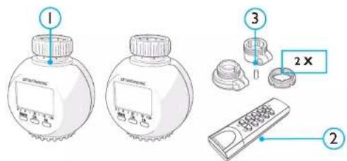
What's in the box of the wireless heating control set?
I Two smart radiator valves
2 A remote control
3 Danfoss fixing rings (2 x)
text_image
1 2 X 34.1 Main components

text_image
smartwares 1 2 3 4 5 6 7 8 9 9a 9b 9c 9d 9e1 Fixing ring
2 LCD display
3 Menu button
Press this button to switch between automatic settings (AUTO), manual settings (Manu) or the holiday position.
4 OK button
5 (*button
This button switches between the 2 settings, high (*) and low ( ).
6 Valve operation
7 Battery compartment
8 Turn button
9 Remote control
a LED
b. ON buttons ( *)
c. OFF buttons ( )
d. ALL-ON button
e ALL-OFF button
f Battery compartment
4.2 Component parts
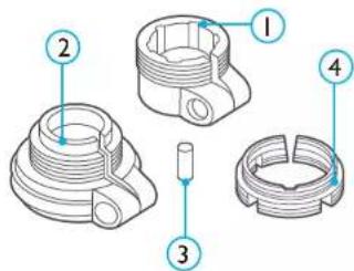
These component parts are applicable for mounting to a Danfoss valve.
(All trademarks and registered trademarks are the property of their respective owners.)
I Danfoss RA ring
2 Danfoss RAV ring
3 Danfoss RAV cap
4 Danfoss RAVL ring (M30 thread)
text_image
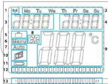
Technical diagram of a mechanical component with numbered parts for identification4.3 Overview display
I RF indicator
2 Day
3 Time
4 Date
5 Holiday position
6 Manual settings
7 Automatic settings
8 Indicator low ( Ⓤ ) and high (* ) temperature
9 The set temperature
10 Window open
II Battery empty indicator
12 Programme Indicator
13 Time indicator
text_image
0:10 Mo Tu We Th Fr Sa Su 28:00 28:00 8 Menu Auto 7.00°C 9 13 1 2.55 First use
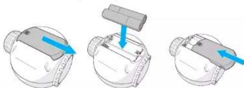
5.1 Placing the batteries
The smart thermostat head
I Slide open the battery lid of the product.
2 Insert 2 AA batteries (not included).
Note the + and - polarity!
3 Slide close the battery lid of the product.
natural_image
Three-step illustration of a robotic device with a handle and blue arrows indicating motion (no text or symbols)Remote control
Activate the battery by pulling the plastic tab from the battery compartment.
This is only necessary when used the first time.
5.2 Set the date and time
I Turn the dial button to set the year.
2 Press OK to confirm.
On the display the month is flashing.
3 Turn the dial button to set the month.
4 Press OK to confirm.
On the display the day is flashing.
5 Turn the dial button to set the day.
6 Press OK to confirm.
On the display the hour is flashing.
7 Turn the dial button to set the hour.
8 Press OK to confirm.
The minutes are flashing on the display.
9 Turn the dial button to set the minutes.
10 Press OK to confirm.
The valve turns in the product and 'ins' is shown on the display. The product is now ready to be mounted on the radiator.
Notice!
• Do not press OK again before the product is mounted on a heater.
- When you wait too long with the setting of the date or the time, the product takes it for granted that the settings have been completed. The valve turns again in the product.
6 Assembly and installation
Notice!
• Follow the steps of chapter 5 if you have not done so already.
• Do not press OK before the product is assembled on a radiator.
- The water from the heating system needs not to be drained when assembling the product.
6.1 Preparation for assembly
- If present, remove the old tap of the radiator. Consult the manual or website of the manufacturer for an exact description.
Notice! Turn the tap to close before removing it. Remove the tap by turning it counterclockwise. - For assembly on a standard valve, follow the steps in paragraph 6.2 and for a Danfoss valve, follow the steps in paragraph 6.3.
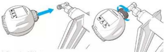
6.2 Assembly on a standard valve
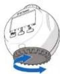
I Pull out the fixing ring until a 'CLICK' is heard.
2 Push the product onto the radiator.
3 Fasten the fixing ring by turning it clockwise.
The product is now mounted to the radiator.
natural_image
Illustration of three different spray gun components with blue arrows indicating motion (no text or symbols)4 Press the OK button.
The valve actuation turns out from the product. 'AdA' appears on the display.
When properly mounted the home screen appears on the display. With an incorrect assembly, an error code (F1, F2 or F3) appears. See chapter 'Failure' for more information.
6.3 Assembly on a Danfoss valve
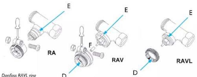
First, determine which of the three Danfoss rings (RA/IPR/RAVL) should be placed on the valve of the radiator. Fix these rings tightly and then place the smart thermostat head.
The radiator contains recesses; make sure that the Danfoss ring fits securely.

WARNING
- Be careful not to catch your fingers between the two parts of a Danfoss ring during installation.
Danfoss RA ring
I Place the RA ring around the valve of the radiator.
Notice! Place the Danfoss ring so that it engages tightly in the recess (E) on the radiator.
2 Bolt on the RA ring using the supplied screw and nut.
Danfoss RAV ring
I Place the RAV cap (F) to the valve on the radiator.
Notice! Place the Danfoss ring so that it engages tightly in the recess (E) on the radiator.
2 Bolt on the RAV ring using the supplied screw and nut.
text_image
Danfoss RAVL ring RA D F RAV D RAVL E E E DDanfoss RAVL ring
I Place the RAVL ring around the valve of the radiator. It needs not to be bolted on.
2 Pull out the fixing ring until a 'CLICK' is heard.
3 Push the product onto the radiator.
4 Fasten the fixing ring by turning it clockwise.
The product is now mounted to the radiator.
5 Press the OK button.
The valve actuation turns out from the product. 'AdA' appears on the display.
When properly mounted the home screen appears on the display. With an incorrect assembly, an error code (F1, F2 or F3) appears. See chapter 'Failure' for more information.
6.4 Reinstallation of the smart thermostat head
Perform the following steps to reinstall the thermostat head, without erasing the memory:
I Keep the Menu button pressed until 'Pro' appears on the display.
2 Choose 'INS' by turning the dial button.
3 Press the OK button.
The valve turns in and out of the product to find the proper adjustment. 'AdA' appears on the display.
7 Operation
7.1 Manual operation of the heating control set
7.1.1 View the current temperature
I Turn the dial button until the desired temperature is shown on the display.
2 On the home screen, press repeatedly on the Menu button until 'Manu' appears.
The manual temperature setting now applies.
I Keep the Menu button pressed until 'Pro' appears on the display.
2 Choose 'tEP' by turning the dial button.
3 Press the OK button.
During the next 30 seconds the smart thermostat head determines the actual temperature.
7.1.3 Setting a high and low temperature
Notice! The low temperature needs to be lower than the high temperature. Otherwise, the setting will not be correct.
I Keep the button pressed until the high temperature appears on the display. This is shown by the * symbol.
2 Set the desired temperature by turning the dial button.
3 Press the OK button.
On the display the low temperature appears. This is shown by the symbol.
4 Set the desired temperature by turning the dial button.
5 Press the OK button.
The home screen appears.
6 Press repeatedly on the (* button to switch between the high and low temperature settings.
7.1.4 Setting Programmes
7.1.4.1 Setting up a programme for a week
You can set up a daily heating programme. The smart thermostat head can be set to 3 different times at which the smart thermostat head will switch to a certain temperature.
I Keep the Menu button pressed until 'Pro' appears on the display.
2 Press the OK button.
At the top of the display day is flashing.
3 Set the desired day by turning the dial button:
Mo = Monday, Tu = Tuesday, We = Wednesday, Th = Thursday, Fr = Friday, Sa = Saturday, Su = Sunday.
4 Press the OK button.
On the display, the time flashes at which the smart thermostat head must switch on for the first time.
5 Set the preferred time by turning the dial button.
6 Press the OK button.
7 On the display, the time flashes at which the smart thermostat head must switch off for the first time.
8 Set the preferred time by turning the dial button.
9 Press the OK button.
10 On the display, the temperature flashes at which the smart thermostat head must switch on for the first time.
II Set the preferred time by turning the dial button.
12 Press the OK button.
On the display, the time flashes at which the smart thermostat head must switch on for the first time.
13 Repeat the previous 7 steps to set the second and third point in time and the corresponding temperature..
Repeat the above steps when you want to set the other days.
- On the home screen, repeatedly press the Menu button until 'AUTO' appears. The set week programme now applies.
Notice! As soon as manual settings are enabled (Manu), the week programmes are disabled.
7.1.4.2 Setting holiday programmes
1 On the home screen, repeatedly press the Menu button until ■ appears. On the display the time is flashing. The temperature setting changes after this period of time to the set holiday position.
2 Set the preferred time by turning the dial button.
3 Press the OK button.
The date flashes.
4 Set the day by turning the dial button.
5 Press the OK button.
6 The temperature flashes.
7 Set the desired temperature for the holiday period by turning the dial button.
8 Press the OK button.
Tip! Press the Menu button to temporarily terminate the holiday programme.
7.1.5 Switching child lock system on or off
Switching on
Press the Menu button and the (*) button simultaneously. 'LOC' appears on the display. The child lock system has now been enabled. The product does not respond when the buttons are pressed or when the dial button is turned.
Switching off
2 Press the Menu button and the (*) button simultaneously when the child lock system is engaged. 'LOC' disappears from the display. The child lock system has now been disabled.
7.1.6 Setting temperature protection in case of ventilation
The smart thermostat head has a temperature protection modus in case of ventilation. When a
decrease in temperature of 1.5 ^ is detected within 3 minutes, the thermostat head switches to a low temperature. The smart thermostat head remains at this low temperature for a certain amount of time.
I Keep the Menu button pressed until 'Pro' appears on the display.
2 Choose 'AEr' by turning the dial button.
3 Press the OK button.
On the display, the minutes flash during which the temperature remains low.
4 Set the number of minutes by turning the dial button.
5 Press the OK button.
On the display the temperature is flashing. The smart thermostat head switches to this temperature when ventilation has been detected.
6 Set the temperature by turning the dial button.
7 Press OK to confirm.
7.1.7 Adjusting the date and time
I Keep the Menu button pressed until 'Pro' appears on the display.
2 Choose 'dAT' by turning the dial button.
3 Press the OK button.
The year appears.
4 Turn the dial button to set the year.
5 Press OK to confirm.
6 Turn the dial button to set the month.
7 Press OK to confirm.
8 Turn the dial button to set the day.
9 Press OK to confirm.
10 Turn the dial button to set the hour.
II Press OK to confirm.
12 Turn the dial button to set the minutes.
13 Press OK to confirm.
The date and time have been adjusted. Press the Menu button to return to the home screen.
7.1.8 Set a temperature correction
If you use the smart thermostat head in combination with a wall thermostat, then the wall thermostat determines the room temperature. It is thus possible that it is colder or warmer elsewhere in the room. To compensate for this, a temperature variance can be set. For example: when your wall thermostat measures 22 degrees and the smart thermostat head measures 24 degrees, then you can adjust the smart thermostat by 2 degrees. Proceed as follows:
I Keep the Menu button pressed until 'Pro' appears on the display.
2 Choose 'tOF' by turning the dial button.
3 Press the OK button.
'0.0 °C' appears on the display.
4 Set the preferred offset temperature by turning the dial button.
5 Press OK to confirm.
7.1.9 Resetting to factory settings
I Keep the Menu button pressed until 'Pro' appears on the display.
2 Choose 'rES' by turning the dial button.
3 Press the OK button.
'rES' flashes on the display.
4 Press OK to reset the thermostat head to the factory settings. Press the Menu button to cancel.
7.2 Operating the heating control set with remote control
Using the remote control the heating can be set to a high or low temperature. To this end, the smart thermostat head needs first to be set on a high* and low (temperature. For more information, see sub-section 6.1.3.
The range of a remote control is 50 metres, which means that you can easily enable the smart thermostat head from the other side of the house.
7.2.1 Setting a high or a low temperature
Notice! The smart thermostat head can be connected to up to 3 wireless devices (such as the HomeWizard, a remote control or a sensor). When the memory is full, (FULL) appears on the display. Refer to Chapter 9 for more information.
I Keep the Menu button pressed until 'Pro' appears on the display.
2 Choose 'rFS' by turning the dial button.
Notice! Make sure that you choose 'rFS' and not 'rES'. When you chose 'rES' and follow the steps below, you reset the smart thermostat head to the factory settings.
3 Press the OK button.
The smart thermostat head arrives in the coupling position. Within 30 seconds a remote control can be coupled or decoupled.
4 Perform one of the following actions:
a. Press one of the ON buttons to couple the remote control. When a beep sounds, the remote control has been coupled.
b. Press one of the OFF buttons to decouple the remote control. When a beep sounds, the remote control has been decoupled.
c. Press the ALL OFF button to disconnect all remote controls. When a beep sounds, all remote controls have been decoupled.
7.2.2 Operate the smart thermostat head with a remote control
1 Set the preferred smart thermostat head to a high and low temperature. See sub-section 7.1.3 for more information.
2 Perform one of the following actions:
3 Press the ON button to connect the smart thermostat head to the high adjusted temperature.
4 Press the OFF button to connect the smart thermostat head to the low adjusted temperature.
7.2.3 Disconnect all remote control devices via the smart thermostat head
I Keep the Menu button pressed until 'Pro' appears on the display.
2 Choose 'UnL' by turning the dial button.
3 Press the OK button.
'UnL' flashes on the display.
4 Press OK to disconnect all paired remote control devices. Press the Menu button to canceln.
Notice! This device is compatible with HomeWizard. HomeWizard enables you to operate this device with an app on your Smartphone or tablet. For more information about HomeWizard visit the website www.HomeWizard.com.
7.3 Operating the heating control set with Homewizard
7.3.1 How do I add the smart thermostat head to the HomeWizard app?
Notice! The smart thermostat head can be linked to up to 3 external devices. When the memory is full, (FULL) appears on the display. Refer to Chapter 9 for more information.
I Open the HomeWizard app on your Smartphone or tablet.
2 Keep the Menu button pressed until 'Pro' appears on the display.
3 Choose 'rFS' by turning the dial button.
Notice! Make sure that you choose 'rFS' and not 'rES'. When you chose 'rES' and follow the steps below, you reset the smart thermostat head to the factory setting
4 Press the OK button.
The smart thermostat head waits in the coupling position. Within 30 seconds the smart thermostat head can be linked-up with the HomeWizard app.
5 On the upper left corner of the screen, press the 'Menu' button (the three lines above each other). The menu appears.
6 Press 'New Sensor'.
Tip! Move your finger across the screen to search.
7 Press 'Thermostatic head'.
8 Press 'Radiator valve Name'. Fill in a preferred name for the device and press 'OK' (Android) or 'Ready' (iOS).
9 Press 'Code' and then press 'Generate new code'.
A beep sounds, and the smart thermostat head is linked up with HomeWizard.
10 Press the check mark in the upper right of the screen.
The smart thermostat head has been added to the HomeWizard app and is to be found on the home screen under 'Thermostat head'.
Perform the above steps for the other heating controller. See paragraph 8.7 for adding a remote control.
7.3.2 How do I set the temperature?
On the Home screen of the HomeWizard app press 'Thermostat head'. A drop-down menu appears with the smart thermostat head added by you.
2 Tap on the name of the preferred thermostat head.
A pop-up appears.
3 Move your finger across the screen to choose the correct temperature.
4 Press 'Set' to set the temperature.
7.3.3 How do I enable or disable the smart thermostat head?
1 On the Home screen of the HomeWizard app press 'Thermostat head'. A drop-down menu appears with the smart thermostat head added by you.
2 Perform one of the following actions:
a. Press the 📄 icon to connect the smart thermostat head to the high adjusted temperature.
b. Press the icon to connect the smart thermostat head to the low adjusted temperature.
7.4 Other HomeWizard applications
You can also use the smart thermostat head in combination with actions, timers and scenes!
Actions: if you also linked a thermometer to your HomeWizard, then, in one and the same action you can also set the thermostat head to switch 'on' by itself when a particular temperature has been measured.
2 Timers: add a timer to the thermostat head in the HomeWizard app to let it go to a certain temperature at a desired point in time.
3 Scenes: add several thermostat heads to a 'scene' so that with one press of the button, you can provide all thermostat heads with the same preferred temperature simultaneously.
8 Maintenance
- The product is maintenance-free, so do not open it. The warranty shall lapse if you open the product.
- Check once a month whether the fixing ring is properly fixed. Bolt the fixing ring tight if it is loose.
- Replace the batteries when the battery indicator begins to flash.
Notice! The memory of the product is saved for 1 minute only.
9 Failures
| Storing Cause Oplossing | ||
| Information on display not visible | - Batteries empty- Batteries inserted incorrectly | Replace the batteriesInsert the batteries correctly in the product |
| The battery symbol flashes | Batteries are almost empty | Replace the batteries. Note! The memory of the product is saved for 1 minute only. |
| Display shows F1 The valve is not responding properly | Re-install the product on the radiator | |
| Display shows F2 The valve is too far from the radiator | Bolt on the fixing ring and ensure that there is less distance between the radiator and the thermostat head. | |
| Display shows F3 Hot ventiel zit to dicht op de radiator | Loosen the ring and ensure that there is more distance between the radiator and the thermostat head. | |
| Display shows FULL The memory is full Disconnect one external device of the smart thermostat head or disconnect all external devices of the smart thermostat head | ||
10 Warranty
This device has a limited two-year warranty. For the guarantee conditions go to: www.smartwares.eu.
II Technical specifications
| Required batteries heating controller (not included): | 3V DC, 2x 1,5V DC, non-rechargeable penlight batteries, type AA |
| Required remote control battery: 12 VDC, 1 x A23 | |
| Measured range: 0 ... 29.5°C | |
| Setting range: | 5 ... 28°C |
| Measurement accuracy: | +/- 0.5°C |
| Temperature span: | 1°C or 2°C adjustable |
| Measured cycle: | 2 minutes |
| Ambient temperature: | 0 ... 35°C |
| Storage temperature: | -20 ... 70°C |
| Humidity: | 5 ... 90% relative |
| Power consumption: | Max. 100 mA |
| Standby power consumption: | Max. 500 μA |
| Frequency: | 433.92 MHz |
| Reception range: | Max. 30 m |
| Other: | Use exclusively in |


Eindhalt
1 Vorwort....33
2 Einführung 33
text_image
Technical diagram of a mechanical component with numbered parts labeled 1 to 4natural_image
Three-step diagram showing a mechanical component with blue arrows indicating direction (no text or symbols)Die Fernbedienung
text_image
Danfoss RAVL Ring E RA F RAV D E RAVL DDanfoss-RAVL-Ring
2 Introduction....49
text_image
Technical diagram of a mechanical component with numbered parts labeled 1 to 44.3 Présentation
natural_image
Three-step diagram showing a mechanical assembly with arrows indicating direction (no text or symbols)La télécommande
natural_image
Illustration of three different spray gun components with blue arrows indicating motion (no text or symbols)Smartwares safety & lighting
Broekakkerweg 15
5126 BD GILZE
Netherlands
Tel: +31 (0)161 - 455 363
smartwares safety & lighting
Broekakkerweg 15 5126 BD Gilze The Netherlands
WWW.SMARTWARES.EU
| NL : 0900-2088888 lokaal tarief |
| BE : 070-233031 lokaal tarief |
| FR : 0825 560 650 15ct/min. |
| DE : +49 (0) 1805 01076214Ct./Min. dt. Festnetz,Mobil max. 42Ct./Min |
| UK : +44 (0) 345 230 1231 |
| ES : +34 938427589 |
CUSTOMER SERVICE