
LNZ81P25 - Surveillance Camera Lorex - Free user manual and instructions
Find the device manual for free LNZ81P25 Lorex in PDF.

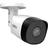
| Product Type | Outdoor PTZ IP Surveillance Camera |
| Brand | Lorex |
| Model | LNZ81P25 |
| Resolution | 4K (8 MP) 3840 x 2160 pixels |
| Sensor | 1/1.8 inch CMOS |
| Lens | Motorized zoom 5.4-135 mm, F1.6-F4.0, 25x optical zoom |
| Horizontal Field of View | 61.6° (wide) to 3.6° (tele) |
| Diagonal Field of View | 66.6° to 4° |
| Night Vision | Color up to 46 m (150 ft) |
| Pan / Tilt | Continuous 360° pan, -15° to 90° tilt |
| Pan/Tilt Speed | Up to 300°/s (manual), up to 400°/s (preset) |
| Presets | 300 positions |
| Advanced PTZ Functions | Guard tours, patterns, auto scans, auto flip |
| Auto Tracking | Yes, with person and vehicle detection |
| Video Compression | H.265/H.264 |
| Power Supply | PoE+ (IEEE 802.3at) 24 W or included 24 V DC power adapter |
| Power Consumption | 24 W max |
| Dimensions (camera only) | 165 x 331 mm (W x H) |
| Weight (camera with mount) | 5.3 kg |
| Housing Material | Aluminum alloy, vandal resistant IK10 |
| Operating Temperature | -40 °C to 70 °C |
| Humidity | < 95% RH |
| Connectivity | RJ45 Ethernet, alarm input/output, audio input/output |
| Local Storage | MicroSD card slot (up to 128 GB, class 10+) |
| Cleaning | Damp cloth only, no chemicals |
| Warranty | Refer to included documentation |
| Included Accessories | Wall mount, power adapter, safety tether, waterproof connectors, mounting tools |
Frequently Asked Questions - LNZ81P25 Lorex
User questions about LNZ81P25 Lorex
0 question about this device. Answer the ones you know or ask your own.
Ask a new question about this device
Download the instructions for your Surveillance Camera in PDF format for free! Find your manual LNZ81P25 - Lorex and take your electronic device back in hand. On this page are published all the documents necessary for the use of your device. LNZ81P25 by Lorex.
USER MANUAL LNZ81P25 Lorex
natural_image
White LOREX security camera mounted on a wall-mounted unit (no visible text or symbols on the device body)Thank you for purchasing this product. Lorex Technology Inc. is committed to providing our customers with a high quality, reliable security solution.
This manual refers to the following models:
LNZ81P25
For the latest online manual, downloads and product updates, and to learn about our complete line of accessory products, please visit our website at:
lorex.com
WARNING
RISK OF ELECTRIC SHOCK DO NOT OPEN
WARNING: TO REDUCE THE RISK OF ELECTRIC SHOCK DO NOT REMOVE COVER. NO USER SERVICEABLE PARTS INSIDE.
REFER SERVICING TO QUALIFIED SERVICE PERSONNEL.
The lightning flash with arrowhead symbol, within an equilateral triangle, is intended to alert the user to the presence of uninsulated "dangerous voltage" within the product's enclosure that may be of sufficient magnitude to constitute a risk of electric shock.
The exclamation point within an equilateral triangle is intended to alert the user to the presence of important operating and maintenance (servicing) instructions in the literature accompanying the appliance.
WARNING: TO PREVENT FIRE OR SHOCK HAZARD, DO NOT EXPOSE THIS UNIT TO RAIN OR MOISTURE.
CAUTION: TO PREVENT ELECTRIC SHOCK, MATCH WIDE BLADE OF THE PLUG TO THE WIDE SLOT AND FULLY INSERT.
Table of contents
1 Safety Instructions .... 1
2 Getting Started.... 2
3 Connecting the Camera .... 3
3.1 Option 1: Connecting the Camera to an NVR.... 3
3.2 Option 2: Connecting Cameras to the Local Area Network (LAN) ...... 3
3.3 Adding the PTZ Camera to an NVR: 5
4 Installation 7
4.1 Installation Tips & Warnings 7
4.2 Installation (Indoor / Outdoor) 7
5 Controlling the PTZ camera with the N883 Series NVR ... 15
5.1 Controlling the PTZ Camera....15
5.2 Advanced PTZ Controls....16
5.2.1 Presets....16
5.2.2 Tours 17
5.2.3 Patterns....17
5.2.4 AutoScan 17
6 Auto Tracking ....18
6.1 Enable Smart Motion Plus (for Auto Tracking) in Smart Plan....18
6.2 Create a Preset for Auto Tracking ....19
6.3 Configuring Auto Tracking ....19
6.4 Disable Auto Tracking....22
7 Inserting the microSD Card (Optional) and Resetting the Camera .....24
8 Troubleshooting....25
8.1 Troubleshooting 25
9 Technical Specifications ....26
9.1 Dimensions....27
9.1.1 Camera & Wall Mount....27
9.1.2 Wall Mount 27
9.1.3 Wall Mount Holes & Cable Hole....28
Safety Instructions1
- Read this guide carefully and keep it for future reference.
- Follow all instructions for safe use of the product and handle with care.
- Use the camera within given temperature, humidity, and voltage levels noted in the 9 Tec cal Specifications, page 26.
- Camera is rated for outdoor use and is weatherproof when properly installed. Camera is not intended for submersion in water. Installation under a sheltered environment is recommended
- Make sure to disconnect the power cabling before installing the camera. Camera will begin moving immediately when power cable is connected.
- Periodic cleaning may be required. Use a damp cloth only. Do not use anything other than water to clean the dome cover, as chemicals such as acetone can permanently damage the plastic.
- Do not disassemble the camera.
- Do not point the camera directly towards the sun or a source of intense light.
- Make sure to secure the camera during installation by connecting the included safety chair.
- Mount the camera in an area that is visible but out of reach.
- Make sure to install the camera in a location that can support the combined weight of the camera and wall mount (weight: 11.7lb/5.3kg).
- Make sure there are no live electrical cables in the area where you plan to mount the c.
- Ensure that the camera wiring is not exposed or easily cut.
- Use only the supplied regulated power supply. Use of a non-regulated, non-conforming power supply can damage this product and voids the warranty.
- Ensure you adhere to local building codes.
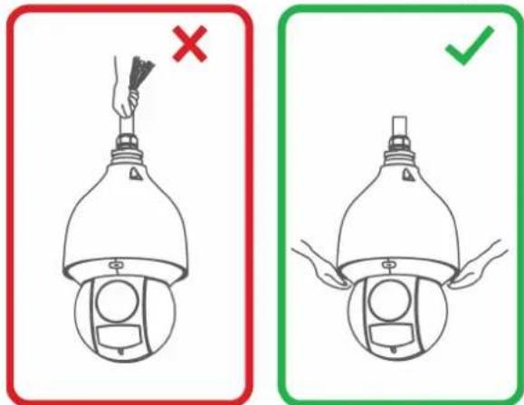
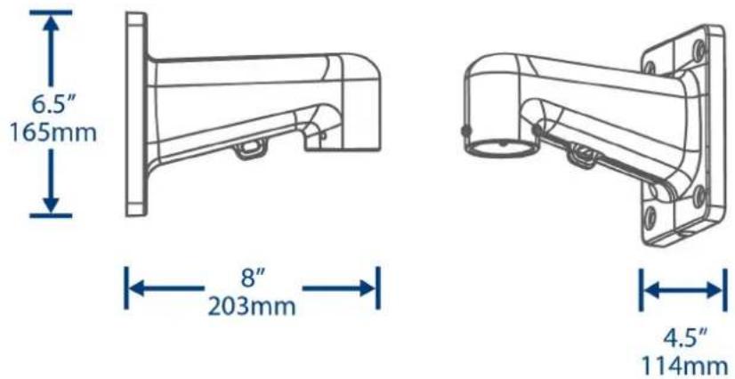
- Do not hold the camera from the cable. Hold the camera from the edge of the dome cov
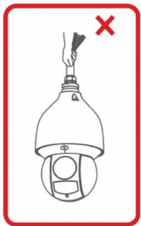
natural_image
Diagram of a hand holding a tool above a device with a red X mark, no text or symbols present
natural_image
Illustration of a hand holding a spray bottle with a green checkmark indicating approval (no text or symbols present)Getting Started2
The camera comes with the following components:
 PTZ Camera Wall Mount Power Adapter PTZ Camera Wall Mount Power Adapter | 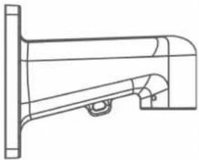 | 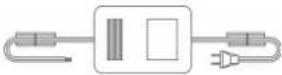 |
 Mounting anchors, screws, flat washers (x4) Mounting anchors, screws, flat washers (x4) | 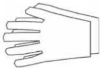 ESD Gloves Safety Chain ESD Gloves Safety Chain | 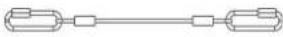 |
 Waterproof Tape Waterproof Connector Allen Key Waterproof Tape Waterproof Connector Allen Key | 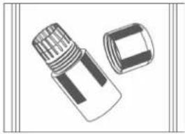 | 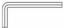 |
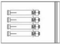
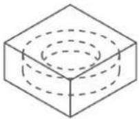
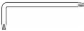 Torx Key M6x14 Screws (x3) Rubber Ring Torx Key M6x14 Screws (x3) Rubber Ring | 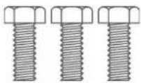 |  |

NOTE
Your accessories might appear different from the ones depicted in this guide.
The following are user supplied tools (not included). You will need use:
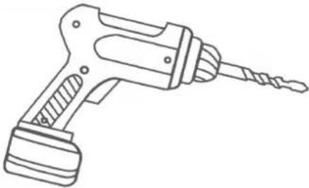 Drill Screwdriver Drill Screwdriver | 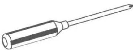 |
Connecting the Camera3

NOTE
It is recommended to connect the camera to your NVR and test the PTZ controls before permanen. For instructions on how to set up PTZ controls, see 5 Controlling the PTZ camera with the N883 Series NVR, page 15.
installatic
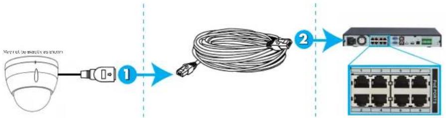
3.1 Option 1: Connecting the Camera to an NVR
flowchart
graph LR
    A["Packet transmission device"] --> B["Wireless router"]
    B --> C["Coiled cable"]
    C --> D["Server switch"]
    D --> E["Network Rack with 6 ports and 10x network connection"]
-
Connect the PoE+ connector on the camera cable to an Ethernet extension cable.
-
Connect the Ethernet extension cable to one of the PoE+ ports on the back panel of yo NVR.

NOTE
- You can use up to a 300ft (91m) CAT5e Ethernet cable to connect the camera to your NVR (not included).
• For the most up-to-date list of compatible NVRs, please visit lorex.com/compatibility.
-
Alarm: Connect the camera to an alarm system using alarm output (blue), alarm communication (green), alarm ground (yellow and green), alarm input (red and/or brown).
-
Audio: Connect the camera to external audio device using audio output (red), audio input (white), and audio ground (black).
3.2 Option 2: Connecting Cameras to the Local Area Network (LAN)
For flexibility, you may also connect the camera to the same Local Area Network (LAN) a NVR. This is accomplished by connecting the camera to the same router as the NVR. For installations, an external PoE+ switch (sold separately) or power adapter (included) must be 1 to provide power to the camera. You also must add the camera on the NVR before it will picture on the monitor or be recorded by the NVR.
What is PoE+?
PoE (Power over Ethernet) is a technology that allows Ethernet cables to carry electrical power to connected devices. High-powered devices such as PTZ cameras use PoE+ (also known as class 4 or IEEE 802.3at), which provides more power to connected devices than standard PoE+ Compatible NVRs use integrated PoE+ ports to provide power and PTZ commands to the camera, as well as video connection to the NVR. PoE+ ports will provide up to 30W to each connected device, whereas standard PoE (class 3) ports only provide up to 15W. In order to use PoE+ rated camera without a power adapter, you must connect it directly to a compatible N or a PoE+ switch on the same network as the NVR. PoE+ switches are available for purchasing lorex.com .
Complete the following steps to connect the camera to the NVR over the LAN.
Step 1 of 2 — Option A: Connecting the camera to your local network using an optional PoE+ switch:
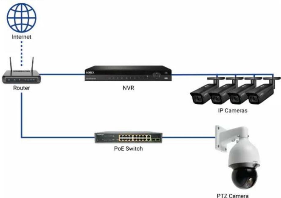
flowchart
graph TD
    A["Internet"] --> B["Router"]
    B --> C["NVR"]
    C --> D["IP Cameras"]
    C --> E["POE Switch"]
    E --> F["PTZ Camera"]
- Connect an Ethernet cable of up to 300ft (91m) rated CAT5e or higher (not included) from the LAN port on an external PoE+ switch (sold separately on lorex.com) to your router. Connect the power cable to the PoE+ switch and to a power outlet or surge protector.

NOTE
Terminology may vary depending on the model of PoE+ switch you have.
- Connect the camera to the PoE+ switch using an Ethernet cable (or a CAT5e Ethernet c of up to 300ft (91m) — not included). The PoE+ switch will provide power and video mission the same way as your NVR.
- Alarm: Connect the camera to an alarm system using alarm output (blue), alarm communication (green), alarm ground (yellow and green), alarm input (red and/or brown).
- Audio: Connect the camera to external audio device using audio output (red), audio input (white), and audio ground (black).
Step 1 of 2 — Option B: Connecting the camera to your local network using a power adapter:
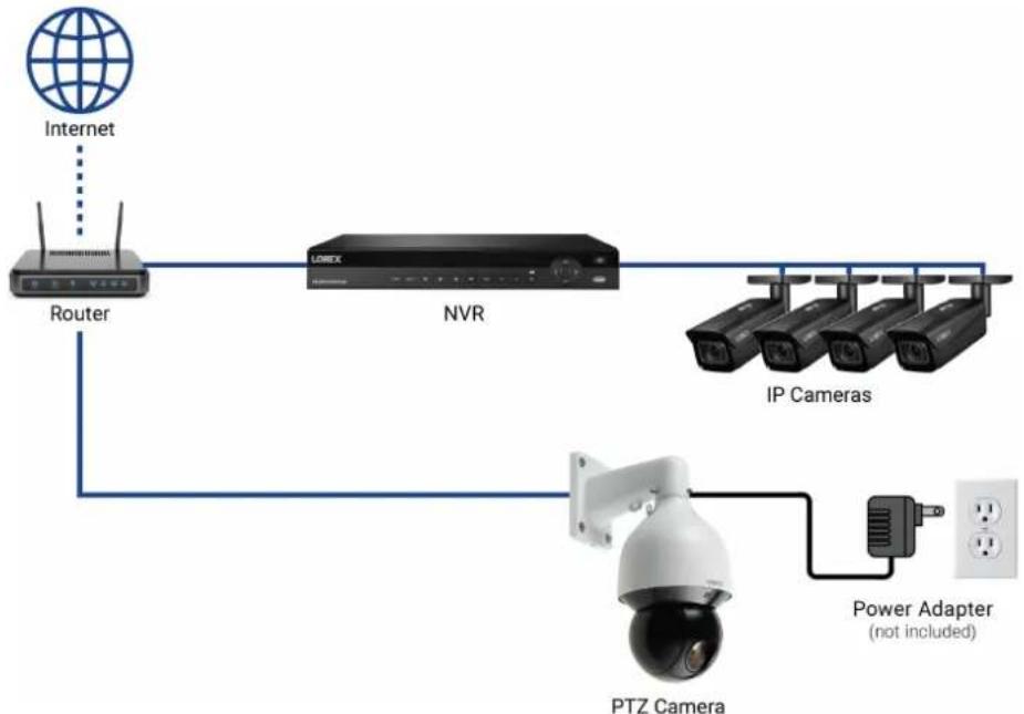
flowchart
graph TD
    A["Internet"] --> B["Router"]
    B --> C["NVR"]
    C --> D["IP Cameras"]
    D --> E["PTZ Camera"]
    E --> F["Power Adapter (not included)"]
    B --> G["Wireless Device"]
- Connect the camera to the included power adapter using red for DV24V(+), black for Gl(-), yellow & green for earth.
- Connect the camera to a router in the same network as your NVR using an Ethernet can an Ethernet cable of up to 300ft (91m) rated CAT5e or higher — not included).
- Alarm: Connect the camera to an alarm system using alarm output (blue), alarm communication (green), alarm ground (yellow and green), alarm input (red and/or brown).
- Audio: Connect the camera to external audio device using audio output (red), audio input (white), and audio ground (black).
Step 2 of 2: Add the camera to your NVR:

NOTE
For instructions on how to locate the serial and model number of your recorder, visit www.lorextechnology.com and search for "Where is the Serial and Model Number located".
3.3 Adding the PTZ Camera to an NVR:
The following instructions are based on the N842/N862 Series NVRs. See your NVR's instruction manual for instructions on controlling the PTZ camera with your system.

NOTE
You must have at least one empty channel before attempting to add the camera to the .
- Right-click during live view and select Add Camera.
-
Log in using the admin account (default User Name: admin; default Password: 000000).
-
Click Search Device. The system searches the network for compatible cameras.
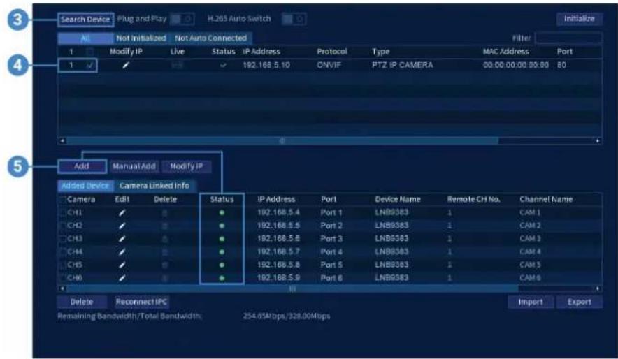
- Check the camera(s) you would like to add.
- Click Add. The Status indicator turns green to show the camera is successfully connected

NOTE
You can also add a camera to a specific channel by hovering the mouse over an empty channel in split-scri view and clicking. Click Device Search and double-click the camera you would like to add. Right click to exit.
Installation4
4.1 Installation Tips & Warnings

WARNING
Make sure to install the camera in a location that can support the combined weight of the camera and wall mount (weight: 11.7lb/5.3kg).
- Camera is rated for outdoor use. It is recommended to install the camera in a sheltered; such as under the eaves on a roof.
- It is recommended to install the camera as high up as possible to get the best possible
- Mount the camera where the lens is away from direct and intense sunlight.
- Plan your cable wiring so that it does not interfere with power lines or telephone lines.
- Ensure you adhere to local building codes.
- Ensure that the camera wiring is not exposed or easily cut.
- Mount the camera in an area that is visible but out of reach.

NOTE
This camera includes all components required for wall mounting.
For the most up-to-date software and complete instruction manuals:
- Visit lorex.com.
- Search for the model number of your product.
- Click on your product in the search results.
- Click on the Downloads tab.
4.2 Installation (Indoor / Outdoor)

CAUTION
- Make sure to disconnect the power cable before installing the camera. Camera will begin moving immediately when power cable is connected.
- Make sure to install the camera in a location that can support the combined weight of the camera and wa mount (11.7lb/5.3kg).
To install the camera on a wall:
- Attach the rubber ring to the back of the wall mount to ensure the weatherproof rating camera.
- Use the Allen key to attach the M6x14 screws (x3) to the wall mount. Do not tighten way.
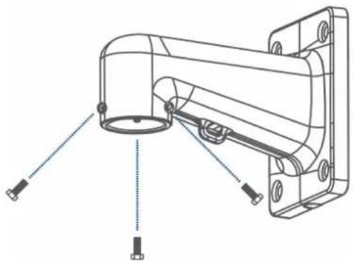
natural_image
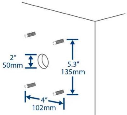
Technical line drawing of a mechanical assembly with mounting brackets and a central cylindrical component (no text or symbols)- Use the included wall mount to mark holes for the mounting anchors (x4) and cables.
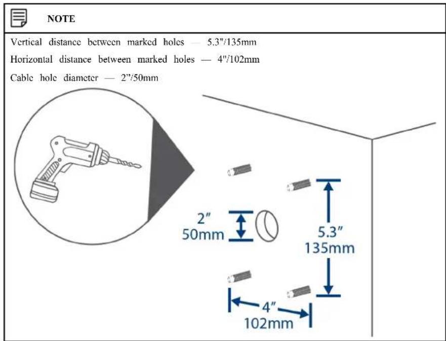
- Drill holes (drill bit size — 3/8") to a depth of 2.8"/70mm in the mounting surface wh marked.
-
Insert the mounting anchors (x4) into the holes and tap them into the wall with a hamn
-
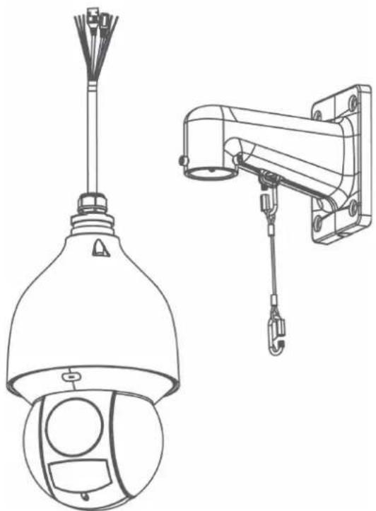
Connect the safety chain between the camera and the wall mount. This allows the camera hang from the wall mount while connecting the cables.
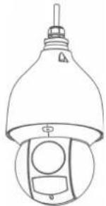
natural_image
Technical line drawing of two security camera components: a spherical lamp and a mounted device (no text or symbols present)
CAUTION
- You must connect the safety chain between the camera and the wall mount to protect the camera from falling while connecting the cables.
- Do not hold the camera from the cable. Hold the camera from the edge of the dome cover
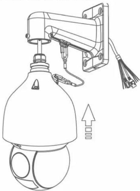
- Push the connection cables into the wall mount
natural_image
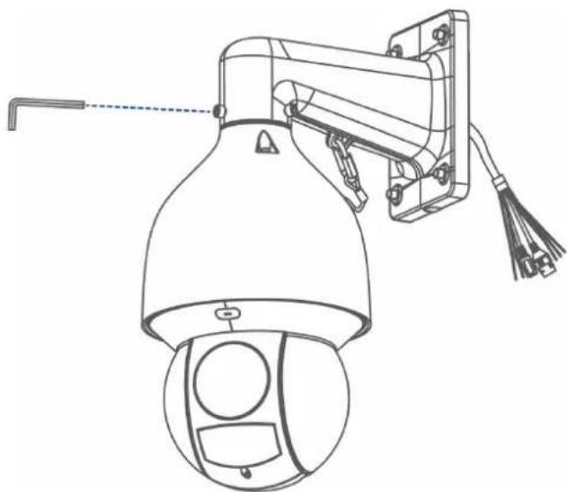
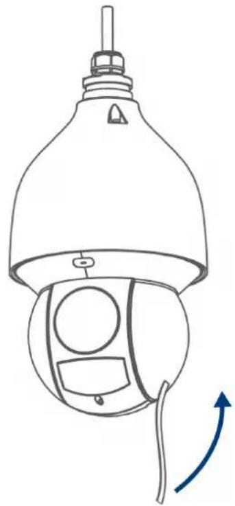
Technical line drawing of a security camera with mounted components and an upward arrow indicating motion (no text or symbols)-
Push the camera into the wall mount with the flat surfaces aligned on the inside. This, low the M6x14 screws (x3) to align with the holes on the camera.
-
Use the included Allen key to tighten the M6x14 screws and secure the camera in place
natural_image
Line drawing of a security camera with mounted sensor and antenna (no text or symbols)- Connect the connection cables.
To connect the cables using the waterproof connector:
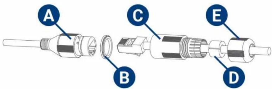
A: Camera Ethernet Connector
B: O-ring
C: Barrel
D: Stopper
E: End Cap
10.1. Fit the o-ring around the camera Ethernet connector.
10.2. Feed the Ethernet extension cable through the end cap and the barrel then connect the cable to the camera Ethernet connector.
10.3. Twist the barrel securely onto the camera Ethernet connector. The o-ring becomes compressed when the scal is properly tight.
10.4. Split the stopper to wrap it around the cable between the barrel and end cap as above.
10.5. Push the stopper toward the barrel until it is underneath the teeth at the end of the barrel.
10.6. Twist the end cap clockwise to secure it onto the barrel. The stopper becomes compressed and will stick out of the end cap slightly when the seal is properly tight
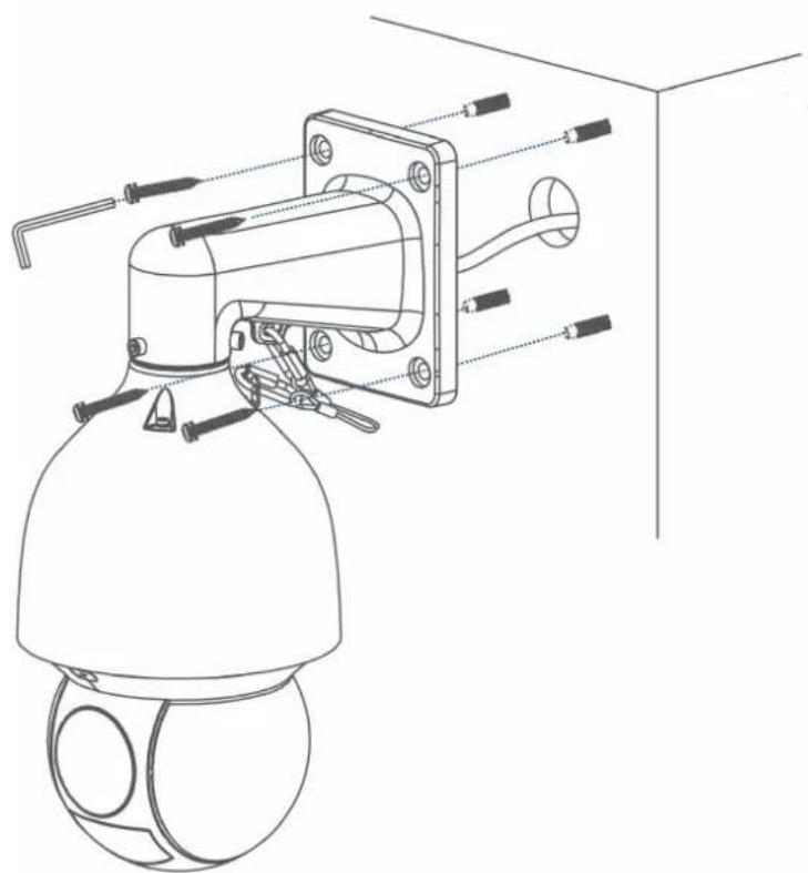
- Pull the connection cables through the wall mount and mounting surface.
-
Attach the flat washers (x4) to the mounting screws (x4).
-
Use the included Torx Key, mounting screws (x4) and flat washers (x4) to firmly attach wall mount to the mounting surface.
natural_image
Technical line drawing of a security camera with attached sensor and connector components (no text or symbols)
NOTE
Imagery for illustration purposes only.

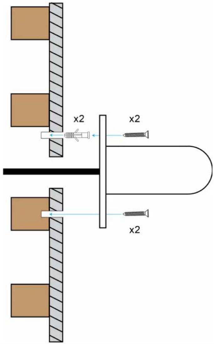
WARNING
Make sure to install the wall mount bracket in a location that can support the camera's weight. If mounting the camera on a drywall surface, you must drill at least 2 of the mounting screws through a ensure a stable mount. See the diagram below for details.
wooden st
- Remove the protective vinyl sheet covering the camera lens once installation is completed
natural_image
Line drawing of a security camera with a bell jar and sensor components, showing no text or symbolsControlling the PTZ camera with the N883 Series NVR
The following instructions are based on the N883 Series. See your 's instruction manual for instructions on controlling the PTZ camera with your system. For the latest list of compatible please visit lorex.com/compatibility.
To connect the PTZ camera to the system:
- Connect the camera to your as detailed in 3 Connecting the Camera, page 3.
- Right-click on the live view of the PTZ camera and click Main Menu. Enter the system name (default: admin) and password (default: 000000) if prompted.
- Click CAMERA, then PTZ.
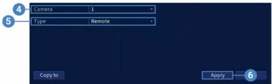
- Under Camera, select your connected PTZ camera.
- Under PTZ, select Remote.
- Click Apply. You can now control your PTZ camera using the system.
5.1 Controlling the PTZ Camera
- In Live View, double-click the channel that has the PTZ camera connected to open in fi screen.
- Right-click and click Pan/Tilt/Zoom. Enter the system user name and password if prompt The PTZ menu opens.
- Use the on-screen controls to control the camera.
PTZ Controls
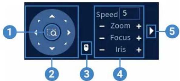
- Zoom-to-Area: Click, then click-and-drag to draw a box on the camera image. The PTZ camera will zoom in to the selected area.
- Navigation Controls: Click the directional arrows to move the PTZ camera manually.
- Mouse Tracking: Click to enable/disable mouse tracking. When enabled, click-and-drag in the direction you would like the PTZ camera to move. The camera will follow the path the mouse cursor.
- PTZ Settings:
• Speed: Enter a PTZ speed between 1 (slowest) and 8 (fastest).
- Zoom: Optical zoom level. Click + to zoom in, and - to zoom out.
- Focus: Manually control focus level. Click + to focus on objects further from the camera, or - to focus on objects closer to the camera.
- Iris: Controls the amount of light coming through the lens. Click + to allow more light, or - for less.
- Advanced: Expand to show advanced options. For a full overview, see 5.2 Advanced PTZ Controls, page 16.
5.2 Advanced PTZ Controls
Advanced PTZ controls can be used to save camera positions and cycle through various positions, and automate camera actions.
To open advanced PTZ controls:
- Click the arrow in the PTZ control window to open advanced controls.
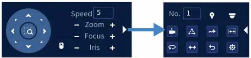
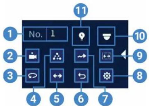
Advanced PTZ controls overview:
flowchart
graph TD
    A["1"] --> B["2"]
    B --> C["3"]
    C --> D["4"]
    D --> E["5"]
    E --> F["6"]
    F --> G["7"]
    G --> H["8"]
    H --> I["9"]
    I --> J["10"]
    J --> K["11"]
    style A fill:#333,stroke:#fff,color:#fff
    style K fill:#333,stroke:#fff,color:#fff
- No.: Enter the ID number for a preset, tour, or pattern you want to activate.
- Preset: Move the camera to the preset number specified in the No. field. For instructions on setting up preset locations, see 5.2.1 Presets, page 16.
- AutoPan: Set the camera to rotate 180^ back and forth.
- Tour: Perform the tour number specified in the No. field. For instructions on creating a tour, see 5.2.2 Tours, page 17.
- Flip: Rotate the camera 180^ from its current position.
- Reset: Move the camera to the home position.
- Pattern: Perform the pattern number specified in the No. field. For instructions on creating a pattern, see 5.2.3 Patterns, page 17.
- Configuration: Click to open the configuration menu, where you can configure presets, tours, patterns and autoscans.
- AutoScan: Move the camera between a predetermined left and right point. For instructions on creating an autoscan, see 5.2.4 AutoScan, page 17.
- OSD Menu: Click to open the camera's OSD menu. This may not be supported on all era models.
- Auxiliary Settings: Not supported.
5.2.1 Presets
Presets will save a camera position for quick retrieval.
To add preset locations:
- From the Live View display of your PTZ camera, right-click to open the Quick Menu, 1 click Pan/Tilt/Zoom.
- The PTZ controls open. Clk to open advanced PTZ controls, then 📄k .
- Click the Preset tab.
- Enter the number of the preset you want to create under Preset.
- Move the camera to the desired position and click Set.
To go to a preset location:
- Under No., select the number of the preset you want to go to, then click
5.2.2 Tours
Tours will cycle through a set of presets.
To add tours:
- From the Live View display of your PTZ camera, right-click to open the Quick Menu, 1 click Pan/Tilt/Zoom.
- The PTZ controls open. Click to open advanced PTZ controls, then click.
- Click the Tour tab.
- Under Patrol No., enter the number of the tour you want to create.
- Under Preset, select a preset you want to add to the tour.
- Click Add Preset.
- Repeat steps 5 & 6 to add additional presets to the tour.
To run a tour:
- Under No., select the number of the tour you want to go to, then click
5.2.3 Patterns
Patterns automatically move the camera according to manually-entered movements.
To add patterns:
- From the Live View display of your PTZ camera, right-click to open the Quick Menu, click Pan/Tilt/Zoom.
- The PTZ controls open. Click to open advanced PTZ controls, then click.
- Click the Pattern tab.
- Under Pattern, enter the number of the pattern you want to create.
- Move the camera to the desired starting position, then click Start.
- Using the on-screen controls, move the camera in any pattern you wish. When finished, End.
To run a pattern:
- Under No., select the number of the pattern you want to go to, then click
5.2.4 AutoScan
An autoscan automatically cycles between a left and right point.
To configure autoscan:
- From the Live View display of your PTZ camera, right-click to open the Quick Menu, 1 click Pan/Tilt/Zoom.
- The PTZ controls open. Click to open advanced PTZ controls, then click.
- Click the Border tab.
- Move the camera into the desired left position and click Left.
- Move the camera into the desired right position and click Right.
To run autoscan:
- Click

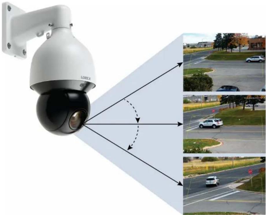
Auto Tracking6
Auto Tracking is an advanced function on the PTZ camera that allows it to cover a large and to automatically detect, follow, and record moving objects, such as a person or vehicle.
The auto tracking technology is composed of both AI detection and tracking. When an object triggers the smart motion plus rule, the PTZ camera will automatically use its pan/tilt rotatic and zoom feature to lock in the moving object in the center of the screen and continue to it without missing any details.
natural_image
Lorex security camera mounted on wall, showing signal propagation and vehicle lane view (no text or symbols)6.1 Enable Smart Motion Plus (for Auto Tracking) in Smart Plan
The smart motion plus feature cannot be used simultaneously with the face detection feature. the smart motion plus feature is not enabled on your IP PTZ camera's smart plan, then the tracking feature will not work. Please make sure the smart motion plus feature is enabled in smart plan before continuing.
To enable smart motion plus in smart plan settings:
-
From the Live View display, right-click to open the Quick Menu, then click Main Menu
-
Click EVENTS. Click the Event Settings tab from the side panel, then the Smart Plan tab from the drop-down.
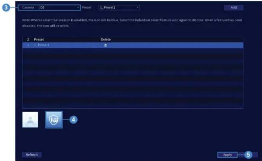
-
Under Camera, select your connected IP PTZ camera.
-
Select the Smart Motion Plus feature.
| NOTE |
| When a smart feature icon is enabled, the icon appears blue. Click the blue smart feature icon able it. When a feature is disabled, the icon appears white. |
- Click Apply to save changes.
6.2 Create a Preset for Auto Tracking
To use the auto tracking function on your PTZ camera, you must create one or more prese sets will save a camera position for quick retrieval. See 5.2.1 Presets, page 16 for full instructions.
6.3 Configuring Auto Tracking
The system allows you to create defined detection areas for auto tracking on moving objects just preferences for auto tracking on your IP PTZ camera.
To configure auto tracking:
-
From the Live View display, right-click to open the Quick Menu, then click Main Menu
-
Click EVENTS. Click the Event Settings tab from the side panel, then the Smart Motion tab from the drop-down.
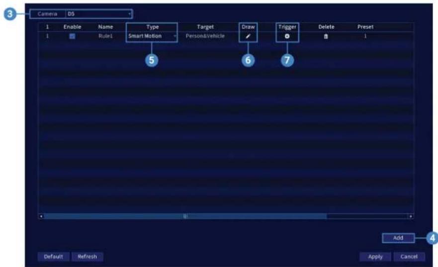
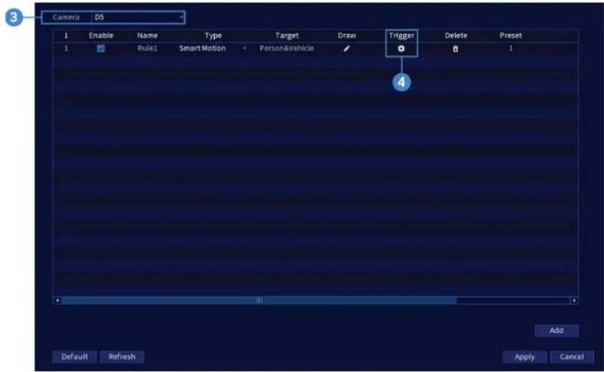
- Under Camera, select your connected PTZ camera.
- Click Add to create a detection rule. Auto Tracking is enabled by default.
-
Under Type, select Smart Motion.
-
Click the Draw ico and customize the active area for auto tracking:
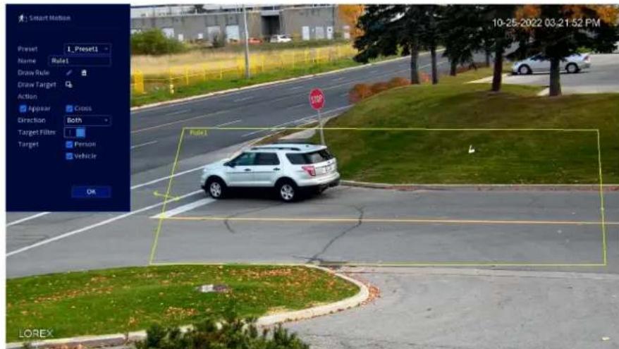
- Preset: Select the preset that you have created for your PTZ camera. If you have not created once, see 5.2.1 Presets, page 16 for full instructions, otherwise auto tracking w not work.
- Name: Set a custom name for the rule.
- Draw Rule: To draw, click around the area, then right-click to close the defined area. most accurate results, set an area where objects of interest will move within the defining area as well as into/out of.
- Action: Check Appear to detect if an object of interest appears in the defined area. Check Cross to detect if an object of interest enters or exits the defined area. Check to enable each type of action.
- Direction: Determine which direction an object needs to travel in order to trigger auto tracking. You can select Enter for movement entering the defined area, or Leave for movement exiting the defined area, or Both for both types of directions.
- Target: Enable the Target Filter. Then check the detection targets Person and/or Vehicle.
- Click OK when finished.
- Click the Trigger ico to set the auto-tracking schedule and to adjust the tracking duration.
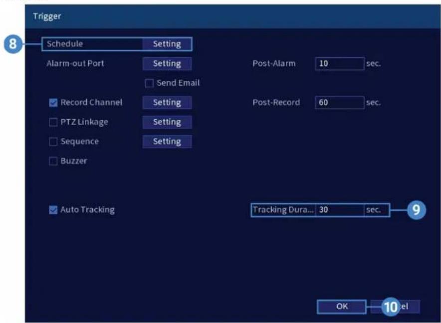
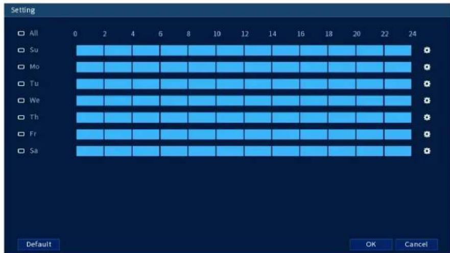
- Click Setting next to Schedule to choose which days and times of the week to enable auto tracking.
-
To adjust how long the camera will automatically track a moving object, enter the Tracl Duration number (next to Auto Tracking).
-
Click OK when finished.
-
Click Apply to save changes.
6.4 Disable Auto Tracking
Stop auto tracking on your PTZ camera by simply disabling the function.
To disable auto tracking:
-
From the Live View display, right-click to open the Quick Menu, then click Main Menu
-
Click EVENTS. Click the Event Settings tab from the side panel, then the Smart Motion tab from the drop-down.
-
Under Camera, select your connected PTZ camera.
-
Click the Trigger icon.
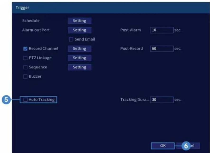
- Uncheck Auto Tracking.
- Click OK, then Apply to save changes.
Inserting the microSD Card (Optional) and Resetting the Camera
The camera features a hard reset button that is used to reset all camera settings back to the fault values. This is useful in case you want to revert camera image settings back to the d values.
To reset the camera:
-
Connect the camera as detailed in 3 Connecting the Camera, page 3. Make sure the came is powered on.
-
Loosen the service panel screws (x4), but do not remove them. Remove the service pane cover.
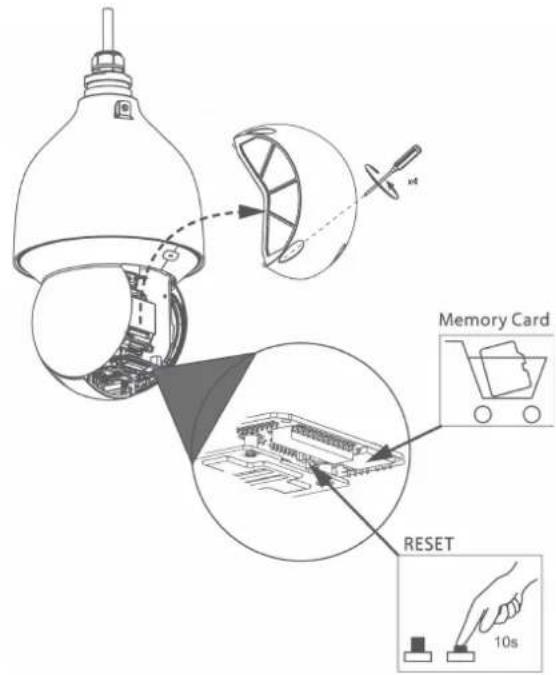
- The service panel allows you to perform the following:
- Insert a microSD card into the microSD card slot. For local recording, you can install microSD card up to 128GB. SanDisk™ or Kingston™ brand microSD cards are recommended, microSD card Class 10 or higher required.
- Press and hold the reset button for 10 seconds to reset the camera to default settings

NOTE
It may take few minutes for the camera image to reappear on the screen.
8.1 Troubleshooting
There is no picture at night.
- Camera is capable of seeing in extremely low light conditions, but it cannot see in total ness. It is recommended to install the camera where there is some ambient light (e.g. street lighting, starlight, moonlight, etc.) or leave a light on in the area where the camera is installed.
No image at startup.
- The camera may take up to 1 minute to power up after being connected to the . Wait minutes before following steps below.
- Check to ensure your camera is properly connected (see 3 Connecting the Camera, page 3)
- If you are using a PoE switch, it must be PoE+ rated (PoE class 4). Standard PoE switch are not adequate to power the camera. PoE+ switches are available for purchase on lorex (model #: ACCLPS263B (16-channel model)).
- Ensure the camera is connected to a router on the same network as the .
- If the camera is connected to the LAN, you must search your network for cameras using See your 's instruction manual for details.
- Make sure that the cable run is within the limitations specified in 3 Connecting the Camer page 3. All Ethernet cables must be rated CAT5e or higher.
- If using the included power adapter, connect it to a different outlet.
- Ethernet cable may be damaged or not connected properly. Check your cable run or try a frequent cable.
- Reset the camera to factory default settings. See 7 Inserting the microSD Card (Optional) and Resetting the Camera, page 24 for details.
No image or camera image is unclear.
- Dome cover is dirty. Clean the dome cover with a soft, slightly damp cloth. Do not use thing other than water to clean the dome cover, as chemicals such as acetone can perma damage the plastic.
Image is distorted.
- Digital zoom is activated. Activating digital zoom may reduce the resolution of the camera image. Zoom out completely to return to the camera's optimal resolution. See 5 Controllin the PTZ camera with the N883 Series NVR, page 15 to be directed to instructions on using the zoom controls.
- Image may become unclear when camera is tilted too close to the camera base (e.g. point parallel to the ceiling). Tilt the camera using PTZ controls.
Image is too bright.
- Ensure your camera isn't pointed directly at a source of light (e.g. sun or spot light).
- Check your 's brightness and contrast settings.
- Move your camera to a different location.
- Enable HDR (High Dynamic Range) in your NVR. HDR is optimized for outdoor environments to help with over- or under-exposed images of scenes with both bright and dark a in the same picture.
Image is too dark.
- Check your 's brightness and contrast settings.
- Move your camera to a different location.
- Enable HDR (High Dynamic Range) in your NVR. HDR is optimized for outdoor environments to help with over- or under-exposed images of scenes with both bright and dark a in the same picture.
motion detection is constantly triggering.
- Turn off motion detection on the channel the PTZ camera is connected to. s use video r detection, which means they detect motion by looking for changes between frames (images in the video. If the camera is moving, the will detect this as motion.
Technical Specifications9
| Video Transmission Technology IP | |
| Image Sensor 8MP/4K 1/1.8" CMOS | |
| Video Format NTSC | |
| Video Compression H.265/H.264 (Main Stream & Sub Stream) | |
| Viewing Angle (Horizontal) 61.6°-3.6° | |
| Viewing Angle (Diagonal) 66.6°-4° | |
| Lens/Lens Type 5.4-135mm F1.6-F4.0 / | Zoom Module |
| Optical Zoom 25× | |
| Digital Zoom Yes - Digital zoom is a function controlled by the connected NVR. For a list of compatible NVRs visit:lorex.com/compatibility. | |
| Pan/Tilt Range | Pan: 0°-360° endlessTilt: -15°~90° |
| Auto Flip | Yes, 180° |
| Continuous Rotation | Yes |
| Manual Speed (Maximum) | Pan: 0.1° 300°/sTilt: 0.1°-140°/s |
| Preset Speed (Maximum) | Pan: 400°/s; Tilt: 300°/s |
| Presets | 300 |
| Patterns | 5 |
| Tours | 8 |
| Other PTZ Functions | Auto Scans, Auto Pan |
| Camera OSD | Yes |
| Motion Detection | Yes |
| Resolution/Frame Rate | Up to 4K (8MP) @ 30fps |
| Effective Pixels | 3840 (H) x 2160 (V) |
| WDR (Wide Dynamic Range) | Yes |
| Termination | RJ45 |
| Night Vision Range 150ft (46m)/ 98ft (30m) | |
| Color Night Vision | Yes |
| Body Material | Aluminum Alloy |
| Vandal Resistant Rating | IK10 |
| Power Requirements | PoE Plus (Power over Ethernet Plus Class -802.3at)/24W |
| Power Consumption (Maximum) | 1A / 24W |
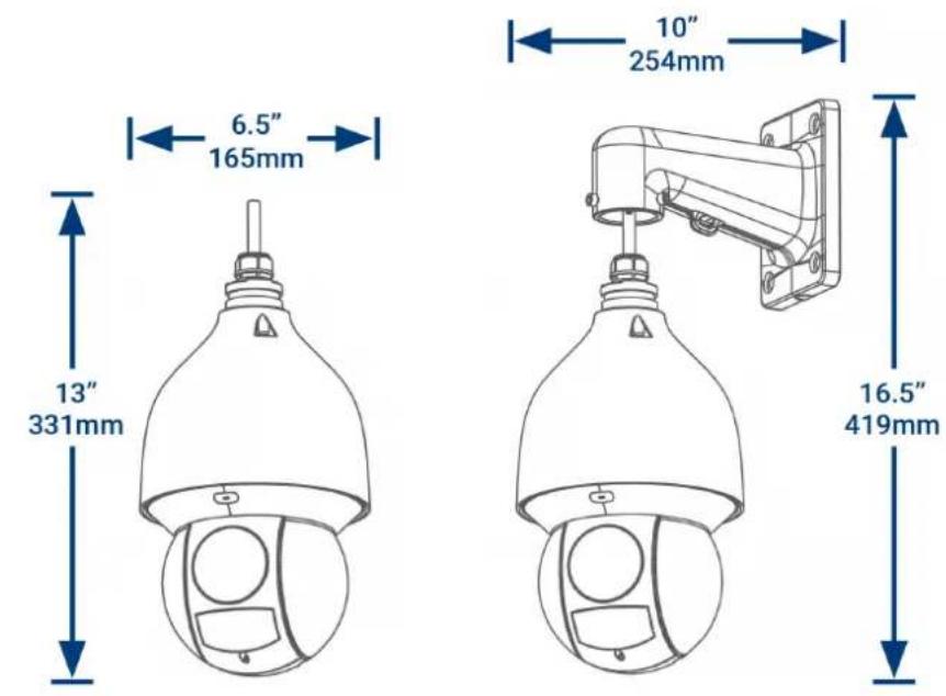
| Camera Dimensions (W x H) | 6.5 × 13" / 331 × 165mm |
| Camera Weight | 11.7lb / 5.3kg |
| Operating Temperature | -40°F ~ 158°F /-40°C ~ 70°C |
| Humidity | < 95% RH |
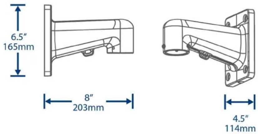
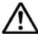
| Dimensions | Camera & Wall Mount = (L) 10" x (W) 6.5" x (H) 16Camera = (W) 6.5" x (H) 13"Wall Mount = (L) 4.5" x (W) 8" x (H) 6.5"Vertical Wall Mount Holes = 5.3"Horizontal Wall Mount Holes = 4"Cable Hole = 2" |
9.1 Dimensions
9.1.1 Camera & Wall Mount
9.1.2 Wall Mount
9.1.3 Wall Mount Holes & Cable Hole
Website
www.lorextechnology.com
Copyright
© 2022, Lorex Corporation
All rights reserved worldwide. Names and marks appearing herein are either registered trademarks or trademarks of Lorex Corporation and/or its subsidiaries. All other trademarks, trade names or company names referenced herein are used for identification only and are the property of their respective owners.
Legal disclaimer
As our product is subject to continuous improvement, Lorex Corporation & subsidiaries reserve the right to modify product design, specifications & prices without notice and without incurring any obligation.E&OE.
natural_image
White LOREX security camera mounted on a wall-mounted unit (no visible text or symbols on the device body)RISQUE D'ÉLECTROCUTION NE PAS OUVRIR
AVERTISSEMENT : NE PAS RETIRER LE COUVERCLE AFIN DE RÉDUIRE LE RISQUE DE DÉCHARGES ÉLECTRIQUES. AUCUNE PIÈCE INTERNE NE NÉCESSITE. D'ENTRETIEN.

natural_image
Illustration of a hand holding a spray bottle with a circular component and a green checkmark (no text or symbols)Mise en route2
flowchart
graph LR
    A["User device with port"] --> B["Switch"]
    B --> C["Wireless cable"]
    C --> D["Switch"]
    D --> E["Network Port with 6 Ethernet ports"]
flowchart
graph TD
    A["Internet"] --> B["Router"]
    B --> C["NVR"]
    C --> D["IP Cameras"]
    D --> E["PTZ Camera"]
    E --> F["Power Adapter (not included)"]
    B --> G["Wireless Device"]
natural_image
Technical line drawing of a mechanical assembly with mounting brackets and a central cylindrical component (no text or symbols)natural_image
Technical line drawing of two security camera components: a spherical device with a string and cable, and a mounted device with a vertical arm and hook (no text or symbols)
ATTENTION
natural_image
Technical line drawing of a security camera with mounted components and an upward arrow indicating motion (no text or symbols)natural_image
Line drawing of a security camera with mounted sensor and antenna (no text or symbols)natural_image
Technical line drawing of a security camera with mounted components and wiring (no text or symbols)
REMARQUE
natural_image
Line drawing of a security camera with a bell jar and mounted sensor (no text or symbols)natural_image
Lorex security camera mounted on wall, showing signal propagation and vehicle detection (no text or symbols)9.1.2 Support mural
Site Web
www.lorextechnology.com
Droits dauteur
© 2022, Lorex Corporation
natural_image
White LOREX security camera mounted on a wall-mounted unit (no visible text or symbols on the device body)natural_image
Diagram of a hand holding a cable above a device with a red X mark, no text or symbols present
natural_image
Illustration of a hand holding a spray bottle with a circular component, enclosed in a green border (no text or symbols)flowchart
graph LR
    A["Packet transmission device"] --> B["Wireless router"]
    B --> C["Coiled cable"]
    C --> D["Server switch"]
    D --> E["Network Rack with 6 ports and 10x network connection"]
flowchart
graph TD
    A["Internet"] --> B["Router"]
    B --> C["NVR"]
    C --> D["IP Cameras"]
    D --> E["PTZ Camera"]
    E --> F["Power Adapter (not included)"]
    B --> G["Wireless Network"]
natural_image
Technical line drawing of a mechanical bracket assembly with mounting holes and a central cylindrical component (no text or symbols)natural_image
Technical line drawing of two security camera components: a spherical lamp and a mounted device (no text or symbols present)
ATENCIÓN
natural_image
Technical line drawing of a security camera with mounted components and an upward arrow indicator (no text or symbols)natural_image
Line drawing of a security camera with mounted sensor and antenna (no text or symbols)natural_image
Technical line drawing of a security camera with mounted components and wiring (no text or symbols)
NOTA
natural_image
Line drawing of a surveillance camera with a bell jar and sensor components, showing no text or symbolsnatural_image
Lorex security camera mounted on wall, showing signal propagation and vehicle detection (no text or symbols)Sitio Web
www.lorextechnology.com
Derechos de Autor
© 2022, Lorex Corporation

- WARNING
- Table of contents
- Safety Instructions1
- Getting Started2
- NOTE
- Connecting the Camera3
- Option 1: Connecting the Camera to an NVR
- Option 2: Connecting Cameras to the Local Area Network (LAN)
- What is PoE+?
- Adding the PTZ Camera to an NVR:
- Installation4
- Installation Tips & Warnings
- For the most up-to-date software and complete instruction manuals:
- Installation (Indoor / Outdoor)
- To install the camera on a wall:
- CAUTION
- Controlling the PTZ camera with the N883 Series NVR
- To connect the PTZ camera to the system:
- Controlling the PTZ Camera
- PTZ Controls
- Advanced PTZ Controls
- To open advanced PTZ controls:
- Advanced PTZ controls overview:
- Presets
- To add preset locations:
- To go to a preset location:
- Tours
- To add tours:
- To run a tour:
- Patterns
- To add patterns:
- To run a pattern:
- AutoScan
- To configure autoscan:
- To run autoscan:
- Auto Tracking6
- Enable Smart Motion Plus (for Auto Tracking) in Smart Plan
- To enable smart motion plus in smart plan settings:
- Create a Preset for Auto Tracking
- Configuring Auto Tracking
- To configure auto tracking:
- Disable Auto Tracking
- To disable auto tracking:
- Inserting the microSD Card (Optional) and Resetting the Camera
- To reset the camera:
- Troubleshooting
- There is no picture at night.
- No image at startup.
- No image or camera image is unclear.
- Image is distorted.
- Image is too bright.
- Image is too dark.
- motion detection is constantly triggering.
- Technical Specifications9
- Dimensions
- Camera & Wall Mount
- Wall Mount
- Website
- Copyright
- Legal disclaimer
- Mise en route2
- ATTENTION
- REMARQUE
- Support mural
- Site Web
- Droits dauteur
- ATENCIÓN
- Sitio Web
- Derechos de Autor
Brand : Lorex
Model : LNZ81P25
Category : Surveillance Camera