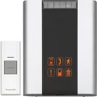
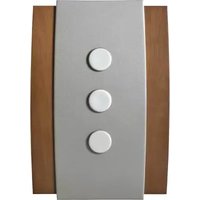
RCWL3506A - Doorbells HONEYWELL - Free user manual and instructions
Find the device manual for free RCWL3506A HONEYWELL in PDF.

| Product type | Decorative wireless doorbell |
| Power supply (doorbell button) | 1 CR2032 battery (included) |
| Power supply (chime) | 4 LR14 alkaline batteries (size C, not included) |
| Battery life (doorbell button) | Approximately 18 months (5 activations/day) |
| Battery life (chime) | Approximately 12 months (5 activations/day) |
| Range (open field) | 140 m (450 ft) |
| Radio frequency | 916.8 MHz |
| Sound level (chime) | 90 dBA at 1 m |
| Number of melodies | Multiple, selectable via button |
| Volume adjustment | Yes, 3 levels |
| Reminder function | Yes, by briefly pressing the programming button |
| Doorbell programming | Up to 4 doorbells per chime |
| Operating temperature (chime) | 0 °C to 40 °C |
| Operating temperature (doorbell button) | -10 °C to 40 °C |
| Weather resistance rating (doorbell button) | Compliant with UL1598 (rain-resistant) |
| Warranty | 1 year from date of purchase |
| Package contents | 1 chime, 1 doorbell button, 1 CR2032 battery, screws, wall plugs, adhesive pad |
| Compatibility | Models of series RPWL30XXX, RCA901N, RCA902N |
Frequently Asked Questions - RCWL3506A HONEYWELL
User questions about RCWL3506A HONEYWELL
0 question about this device. Answer the ones you know or ask your own.
Ask a new question about this device
Download the instructions for your Doorbells in PDF format for free! Find your manual RCWL3506A - HONEYWELL and take your electronic device back in hand. On this page are published all the documents necessary for the use of your device. RCWL3506A by HONEYWELL.
USER MANUAL RCWL3506A HONEYWELL
Installation Instructions
RCWL35 Series
RCWL35N, RCWL3501A, RCWL3502A, RCWL3503A, RCWL3504A, RCWL3505A, RCWL3506A Decorative Wire Free Chimes and Push
Installation Instructions
Contents
Safety 2
Checking pack contents ......2
Open bell push ....3
Install the push battery ....3
Open the chime ....3
Install the chime battery ....3
Test the kits ....4
Volume control 5
Change tunes ....5
Add new push/reprogram 6
Unlearn procedure ....6
Recall function ......6
Mount chime ....7
Paint the wood cover....8
Specifications 9
Troubleshooting 9
Disposal and recycling ....12
Guarantee ....12
Declaration ....13
69-2115EFS-05 ii
RCWL35 Series
Compatible with décor wireless push, converter, motion detector, and door contact. (Model No. RPWL30XXX series, and RCA901N and RCA902N.)
1 69-2115EFS-05
Installation Instructions
Safety
Before proceeding with the installation, please note the following safety warnings:
- Always follow the manufacturer's advice when using power tools and wear suitable protective equipment (e.g. safety goggles) when drilling holes, etc.
- Before drilling holes in walls, check for hidden electricity cables and water pipes. The use of a cable/pipe locator is advisable if in doubt.
Decorative Wire Free Chimes and Push
Checking Pack Contents
- Chime
• Bell push (for chime kit only) - CR2032 battery for bell push (for chime kit only)
- 2 x fixing screws for push (for chime kit only)
- 2 x fixing screws for chime
- Wall plugs
- Adhesive pad (for chime kit only)
69-2115EFS-05 2
You will need:
• A Phillips screwdriver
• A small flat bladed screwdriver
• A 1/4-in. (6 mm) masonry drill
• 4 X LR14 'C' Alkaline batteries
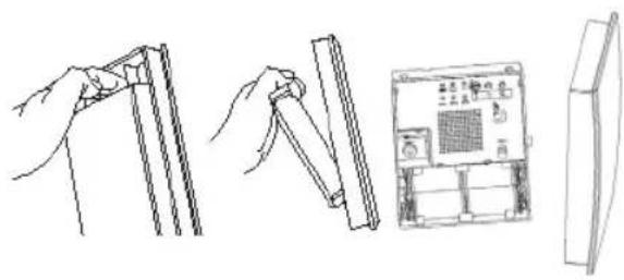
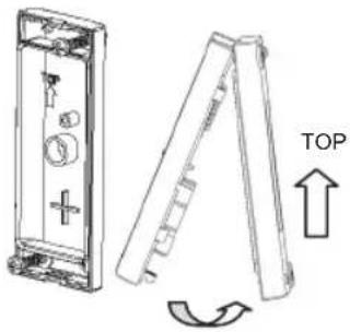
Installation
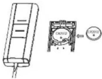
- Open the bell push and insert the push battery (CR2032).
- Open the chime cover.
natural_image
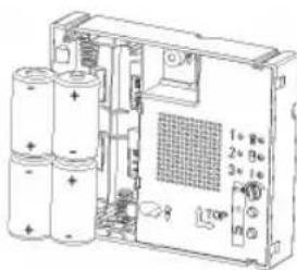
Line drawings showing hands holding cylindrical objects, a pen-like object, and an electronic device with a grid display (no text or symbols)- Insert chime batteries (LR14 C size).
3 69-2115EFS-05
Installation Instructions
Installation
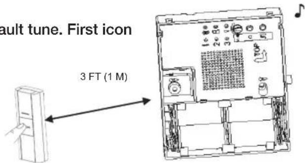
- Operate push. Chime will play the default tune. First icon will illuminate.
Note: The bell push (if supplied) is pre-programmed to operate with the chime.
69-2115EFS-05 4
69-2115EFS_C.indd 4 12/17/2007 2:23:56 PM

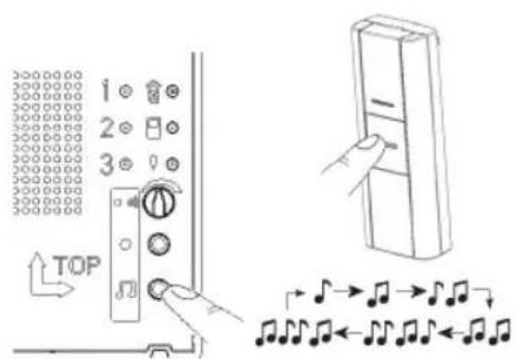
Installation
- To adjust volume.
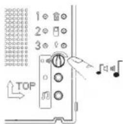
- To change tunes Press push button, chime will play tune, while the icon on chime is flashing, press and release tune button 🎨 Press and release button again to cycle through the available tunes until you hear the tune you want. The last tune played will be stored after the icon stops flashing. To confirm, press the push button and chime will play the tune you want.
5 69-2115EFS-05
Installation Instructions
Installation
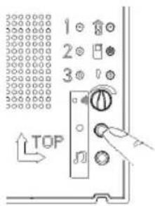
- To add new push/reprogram
Press and hold the program button ●. The icons will illuminate in sequence. Release the program button when icon you choose is illuminated. Operate your new push and the chime will play tune, icon will flash. To change tune, refer to step 6.
- Unlearn procedure
To remove a push from the chime's memory, press and hold the program button ●. Each icon will light in turn. When the icon
associated with the push to be un-learned is lit, release the button. Then press and hold down both ● and ⏻ buttons, until a 'beep' sound is heard.
- Recall function
A short push of the program button ● will flash the icon that was last in use.
69-2115EFS-05 6

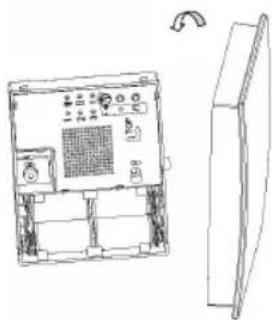
Installation
10. Mount the bell push
Install back cover to wall, use screws provided/adhesive pad. Close the cover.
Note: Before final installation adjust distance and position between push and chime to optimize the chime within your environment. Dense walls and metal can reduce range.
natural_image
Technical line drawing of a mechanical device with an open lid and a side view showing a top view (no text or symbols)| Wall Type Range Reduction | |
| Dry-lined partition wall 10–30% | |
| Single-layer brick wall 20–40% | |
| Double-layer brick wall 30–70% | |
| Metal panel/radiator 90–100% |
7 69-2115EFS-05
Installation Instructions
Installation
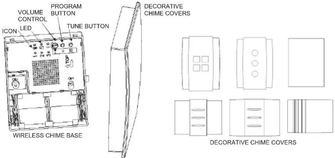
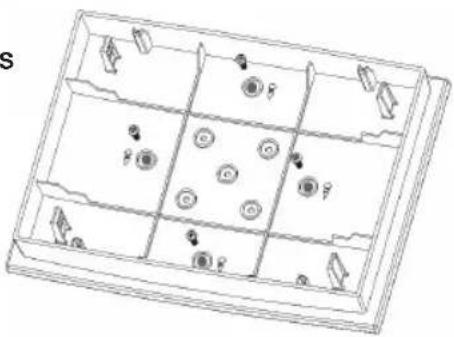
- Mount the chime
Mounting holes are marked with screw symbol. Clip on the front cover.
natural_image
Technical line drawing of a device rear panel with control panel and fan (no text or symbols)
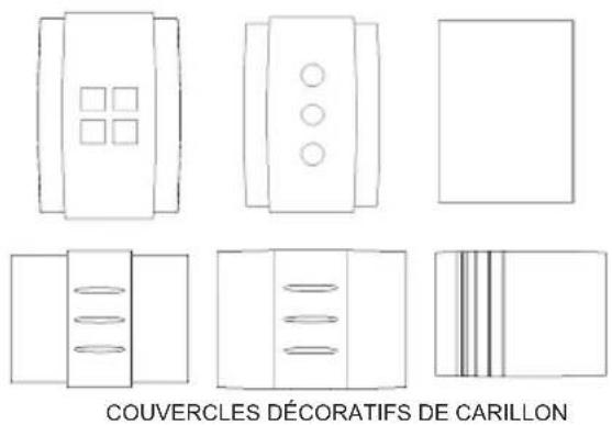
- For stainable covers only
Choose your paint, stain or varnish and then apply to the cover. Follow manufacturers' advice on the paint/vanish. It is possible to unscrew the four screws shown below for painting. Ensure you screw it back with the same screws provided!
Once completed, clip it onto the base as in step 11.
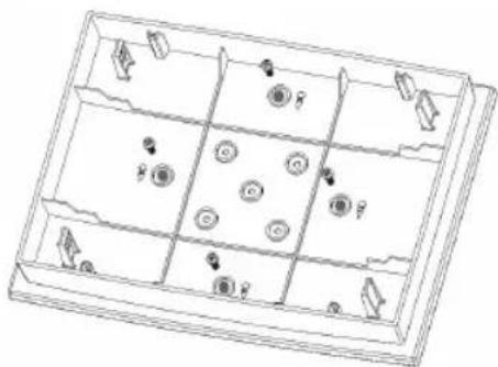
natural_image
Line drawing of a multi-panel storage tray with circular and directional elements (no text or symbols)69-2115EFS-05 8
RCWL35 Series
| Specification Chime Bell push | ||
| Operating Temperature 32°F to 1 | 04°F | 14°F to 104°F |
| 0°C to 40°C | -10°C to 40°C | |
| RF Frequency- US 916.8 MHz 91 | 6.8 MHz | |
| Range (open field) 450 ft. (140 m) | ||
| Sound Level (typical) 90dBA @ 3 | ft. (1 m) - | |
| RF Power - <1mW | ||
| Battery Type | LR14 (C size) | CR2032 |
| Battery Life (5 activations/day) | 12 months | 18 months |
| Rain proof | N/A | Pass UL1598 rain test |
Troubleshooting
A 'beep' sound is heard in learn mode...
- The push you are programming has already been learned by the chime.
- If you want to change the icon associated with the push, use the unlearn procedure, then program the push again.
9 69-2115EFS-05
Installation Instructions
Troubleshooting
Two 'beep' sounds are heard after the normal chime sound...
- This indicates a low battery in the bell push that activated the chime. Install a new battery, type CR2032.
When the bell push is operated, the amber confidence light does not turn on, or is only on for a short time...
- In normal operation, the amber light will turn on for 1 second. When the battery is weak, the light will only turn on for a short time. Install a new battery, type CR2032.
The chime does not work...
- Check that the batteries are the correct type, LR14 'C' cells. Only use alkaline batteries.
- Check that the batteries are fitted correctly. (No wrong polarity)
- The chime could be out of range of the bell push. Try the chime in a different location.
- The chime might not have learned the identity of the bell push. Follow the programming procedure.
69-2115EFS-05 10
Troubleshooting
The chime does not sound...
- Check that the volume control is not at the minimum setting.
Range is reduced...
- Metal structures, including uPVC door frames can reduce the range of the product. Avoid mounting the push or chime on or near metal structures.
- Other equipment can cause radio interference that affects your chime.
- Walls and ceilings will reduce the range.
- Weak batteries will reduce range. Replace every 12–18 months. In cold conditions (below 41°F [5°C]), batteries may need to be replaced more often.
Amber light flashes...
- When the chime battery is low, an amber light located at the side of the chime will flash every 5 seconds. Fit new batteries in the chime, type LR14 'C' cells. Only use alkaline batteries.
11 69-2115EFS-05
Installation Instructions
Disposal & Recycling
Batteries and waste electrical products should not be disposed of with household waste. Please recycle where these facilities exist. Check with your local authority or retailer for recycling advice.
Guarantee
Honeywell guarantees this product for 1 year from the date of purchase. Proof of purchase is required; this does not affect your statutory rights. If you require further information about your product, call the Honeywell helpline at 1-800-468-1502.
69-2115EFS-05 12
69-2115EFS_C.indd 12 12/17/2007 2:23:57 PM

Declaration
Honeywell hereby declares that this product complies with Part 15 of the FCC rules and Industrial Canada standards.
This device operation is subject to the following two conditions:
(1) This device may not cause harmful interference, and
(2) This device must accept any interference received, including interference that may cause undesired operation.

Caution:
Changes or modifications not expressly approved by the party responsible for regulatory compliance could void the user's authority to operate the equipment.

13 69-2115EFS-05

Honeywell International Inc.
ACS, Environmental and Combustion Controls
1985 Douglas Drive, Golden Valley, MN 55422
www.honeywell.com

Printed in U.S.A. on recycled paper containing at least 10% post-consumer paper fibers.
® U.S. Registered Trademark.
© 2007 Honeywell International Inc.
69-2115EFS—05 M.S. Rev. 12-07
69-2115EFS_C.indd 14 12/17/2007 2:23:57 PM
Honeywell
Honeywell
natural_image
Simple line drawing of a 3D rectangular prism with no text or symbolsCOUVERCLES DÉCORATIFS DE CARILLON
natural_image
Illustration showing hands holding cylindrical components and a control panel with a grid (no text or symbols)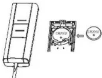
19 69-2115EFS-05

natural_image
Technical line drawing of an electronic device with a side panel and control panel (no text or symbols)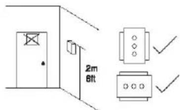
natural_image
Line drawing of a multi-panel storage tray with circular and directional icons (no text or symbols)69-2115EFS-05 24
RCWL35 Serie
Honeywell International Inc.
1985 Douglas Drive, Golden Valley, MN 55422
www.honeywell.com

Copyright © 2007 Honeywell International Inc.
69-2115EFS—05 M.S. Rev. 12-07
69-2115EFS_C.indd 30 12/17/2007 2:23:58 PM
Honeywell
Honeywell
natural_image
Simple line drawing of a rectangular block with a folded edge (no text or symbols)natural_image
Illustration showing hands holding a ruler and a device with a grid, alongside a separate panel (no text or symbols visible)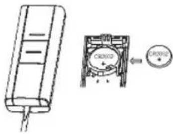
35 69-2115EFS-05

natural_image
Technical line drawing of a device casing with internal components and an arrow indicating top view (no text or symbols)natural_image
Line drawing of an electronic device with a panel and control panel, shown from front and side views (no text or symbols)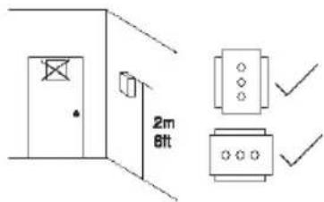
natural_image
Line drawing of a rectangular tray with internal compartments and circular elements (no text or symbols)69-2115EFS-05 40
RCWL35 Serie
Honeywell International Inc.
ACS, Environmental and Combustion Controls
1985 Douglas Drive, Golden Valley, MN 55422
www.honeywell.com

© 2007, Honeywell International Inc.
69-2115EFS—05 M.S. Rev. 12-07
69-2115EFS_C.indd 46 12/17/2007 2:24:00 PM