AFBWCN1 - Basket BEST - Free user manual and instructions
Find the device manual for free AFBWCN1 BEST in PDF.

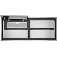
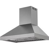
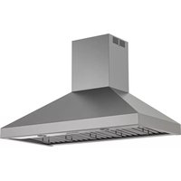
| Product Type | Range Hood |
| Brand | Best (Broan-NuTone) |
| Model | AFBWCN1 |
| Available Width | 30 in (76.2 cm) or 36 in (91.4 cm) |
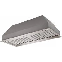
| Installation Type | Vented (duct) or recirculating (with kit ANKWCN1) |
| Required Duct Diameter | 8 in (20.3 cm) round metal |
| Number of Fan Speeds | 4 speeds (1, 2, 3, 4) + delayed shut-off |
| Lighting | 3-level dimmable LED |
| Grease Filters | Aluminum, dishwasher safe |
| Charcoal Filters (optional) | Recommended every 6 months (model S99010512) |
| Hood Material | Stainless steel |
| Minimum Distance Above Cooktop | 24 in (61 cm) |
| Maximum Recommended Distance Above Cooktop | 30 in (76 cm) |
| Electrical Supply | 120 V, 60 Hz, grounding required |
| Motor Protection | Thermal (auto-shutoff in case of overheating) |
| Usage | Indoor, household only |
| Warranty | 5-year limited parts warranty |
| Box Contents | Hood, decorative duct covers (upper and lower), mounting bracket, grease filters, damper, hardware |
| Optional Accessories | Duct extension (AEWCN1SS), recirculation kit (ANKWCN1), baffle filters |
| Weight | Not specified (estimated 25-35 kg) |
Frequently Asked Questions - AFBWCN1 BEST
User questions about AFBWCN1 BEST
0 question about this device. Answer the ones you know or ask your own.
Ask a new question about this device
Download the instructions for your Basket in PDF format for free! Find your manual AFBWCN1 - BEST and take your electronic device back in hand. On this page are published all the documents necessary for the use of your device. AFBWCN1 by BEST.
USER MANUAL AFBWCN1 BEST
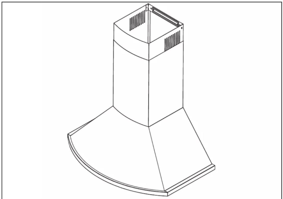
natural_image
Isometric line drawing of a mechanical component with a curved base and top opening (no text or symbols)WCN1 SERIES
READ AND SAVE THESE INSTRUCTIONS
INSTALLER: LEAVE THIS MANUAL WITH HOMEOWNER. HOMEOWNER: USE AND CARE INFORMATION ON PAGE 10.
BEST; Hartford, Wisconsin www.BestRangeHoods.com 800 558-1711 BEST; Drummondville, QC, Canada www.BestRangeHoods.ca 866 737-7770
To register your product online or for additional information visit www.BestRangeHoods.com
TO REDUCE THE RISK OF FIRE, ELECTRIC SHOCK OR INJURY TO PERSONS, OBSERVE THE FOLLOWING:
- Use this unit only in the manner intended by the manufacturer. If you have questions, contact the manufacturer at the address or telephone number listed in the warranty.
- Before servicing or cleaning unit, switch power off at service panel and lock service disconnecting means to prevent power from being switched on accidentally. When the service disconnecting means cannot be locked, securely fasten a prominent warning device, such as a tag, to the service panel.
- Installation work and electrical wiring must be done by qualified personnel in accordance with all applicable codes and standards, including fire-rated construction codes and standards.
- Sufficient air is needed for proper combustion and exhausting of gases through the flue (chimney) of fuel burning equipment to prevent backdrafting. Follow the heating equipment manufacturer's guidelines and safety standards such as those published by the National Fire Protection Association (NFPA) and the American Society for Heating, Refrigeration and Air Conditioning Engineers (ASHRAE) and the local code authorities.
- When cutting or drilling into wall or ceiling, do not damage electrical wiring and other hidden utilities.
- Ducted fans must always be vented to the outdoors.
- Do not use this unit with any solid-state speed control device.
- To reduce the risk of fire, use only metal ductwork.
- This unit must be grounded.
- When applicable local regulations comprise more restrictive installation and/or certification requirements, the aforementioned requirements prevail on those of this document and the installer agrees to conform to these at his own expense.
TO REDUCE THE RISK OF A RANGE TOP GREASE FIRE:
a) Never leave surface units unattended at high settings. Boilovers cause smoking and greasy spillovers that may ignite. Heat oils slowly on low or medium settings.
b) Always turn the hood ON when cooking at high heat or when flambeing food (i.e.: Crêpes Suzette, Cherries Jubilee, Peppercorn Beef Flambé).
c) Clean ventilating fans frequently. Grease should not be allowed to accumulate on fan, filters or in exhaust ducts.
d) Use proper pan size. Always use cookware appropriate for the size of the surface element.
WARNING
TO REDUCE THE RISK OF INJURY TO PERSONS IN THE EVENT OF A RANGE TOP GREASE FIRE, OBSERVE THE FOLLOWING\*:
- SMOTHER FLAMES with a close-fitting lid, cookie sheet or metal tray, then turn off the burner. BE CAREFUL TO PREVENT BURNS. IF THE FLAMES DO NOT GO OUT IMMEDIATELY, EVACUATE AND CALL THE FIRE DEPARTMENT.
- NEVER PICK UP A FLAMING PAN — You may be burned.
- DO NOT USE WATER, including wet dishcloths or towels — This could cause a violent steam explosion.
- Use an extinguisher ONLY if:
A. You own a Class ABC extinguisher and you know how to operate it.
B. The fire is small and contained in the area where it started.
C. The fire department has been called.
D. You can fight the fire with your back to an exit.
* Based on "Kitchen Fire Safety Tips" published by NFPA.
CAUTION
- For indoor use only.
- For general ventilating use only. Do not use to exhaust hazardous or explosive materials and vapors.
- To avoid motor bearing damage and noisy and/or unbalanced impeller, keep drywall spray, construction dust, etc. off power unit.
- Your hood motor has a thermal overload which will automatically shut off the motor if it becomes overheated. The motor will restart when it cools down. If the motor continues to shut off and restart, have the hood serviced.
- The minimum hood distance above cooktop must not be less than 24". For best capture of cooking impurities, the bottom of the hood should be at a maximum of 30" above the cooking surface.
- Two installers are recommended because of the large size and weight of this unit.
- To reduce the risk of fire and to properly exhaust air, be sure to duct air outside — Do not exhaust air into spaces within walls or ceiling or into attics, crawl space or garage.
- Because of the high exhausting capacity of this unit, you should make sure enough air is entering the house to replace exhausted air by opening a window close to or in the kitchen.
- To reduce the risk of fire and electrical shock, the Best WCN1 Series models should only be installed with their own built-in blower.
- When used in recirculation mode, to reduce the risk of fire and shock, use only conversion kit model ANKWCN1.
- Please read specification label on product for further information and requirements.
1. PREPARE INSTALLATION
NOTE: Before proceeding to the installation, check the contents of the box. If items are missing or damaged, contact the manufacturer.
Make sure that the following items are included:
- Hood
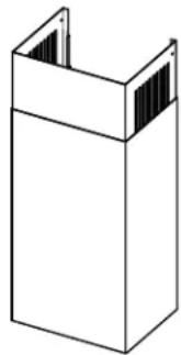
- Accessories • Decorative flue assembly (lower and upper flues)
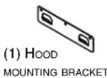
• Hood mounting bracket
• Upper flue mounting bracket
• Aluminum grease filters
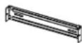
- 8" round damper
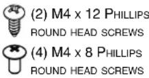
- Bag of parts including: 9 #8 x 1-1/2" Phillips flat head screws, 2 M4 x 12 Phillips round head screws,
4 M4 x 8 Phillips round head screws,
2 washers and 3 wire connectors
- Installation manual
Parts sold separately:
- Duct, elbows, wall or roof caps
- Optional baffle filters kit (set of 2) AFBWCN1
- Optional flue extension for 10'-11' ceilings model AEWCN1SS
- Non-duct kit model ANKWCN1, mandatory for non-ducted installation
NOTE: During installation, protect countertop and/or cooktop.
natural_image
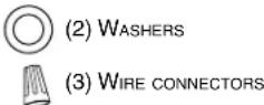
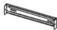
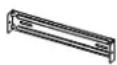
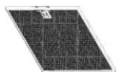
Isometric line drawing of a rectangular box with a U-shaped top and side slats (no text or symbols)(1) DECORATIVE FLUE ASSEMBLY
(1) UPPER FLUE
MOUNTING BRACKET
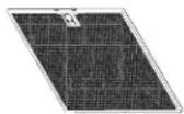
(2) GREASE FILTERS

(9) #8 x 1-1/2" PHILLIPS FLAT HEAD SCREWS
(1) DAMPER
HR0266A
2. SELECT INSTALLATION TYPE
WARNING
When performing installation, servicing or cleaning the unit, it is recommended to wear safety glasses and gloves.
2.1 NON-DUCTED INSTALLATION
The ANKWCN1 non-duct kit is required for a non-ducted installation.
2.2 DUCTED INSTALLATION
Plan where and how the ductwork will be installed.
A straight, short duct run will allow the hood to perform most efficiently. Long duct runs, elbows and transitions will reduce the performance of the hood. Use as few of them as possible. Larger ducting may be required for longer duct runs.
Install wall or roof cap. Connect 8" round metal ductwork to cap and work back towards the hood location. Use 2" metal foil duct tape to seal the joints.
2.3 ALL INSTALLATIONS
The minimum hood distance above cooktop is 24". A maximum of 30" above cooktop is recommended for best capture of cooking impurities.
Distances over 30" are at the installer and users discretion providing that ceiling height and decorative flue length allow it.
NOTE: 10'-11' ceilings require flue extension model AEWCN1SS (stainless steel).
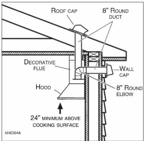
text_image
ROOF CAP 8" ROUND DUCT DECORATIVE FLUE HOOD WALL CAP 8" ROUND ELBOW 24" MINIMUM ABOVE COOKING SURFACE HH0304A3. INSTALL HOOD MOUNTING BRACKET
WARNING
- When cutting or drilling into wall, do not damage electrical wiring and other hidden utilities.
- When building framework, always follow all applicable construction codes and standards.
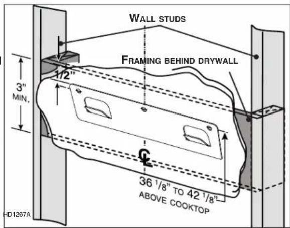
Construct wood wall framing that is even with the surface of wall studs. Wood wall framing must be at least 1/2" thick and 3" high. Fasten wood wall framing to wall studs for a solid installation. Make sure that the height of the framing will allow the mounting bracket to be secured to the framing within the dimensions shown (see illustration at right). After wall surface is finished, using a level, draw a vertical line up to the ceiling starting from the center of the planned hood location. Carefully center and level the hood mounting bracket over installation location. Secure it to wall framing using 3 #8 x 1-1/2" Phillips flat head screws.
text_image
WALL STUDS FRAMING BEHIND DRYWALL 3" MIN. 1/2" G 36 1/8" TO 42 1/8" ABOVE COOKTOP HD1267A36 ^1/8 " = BOTTOM OF HOOD 24" ABOVE COOKTOP
42 ^1 /8" = BOTTOM OF HOOD 30" ABOVE COOKTOP
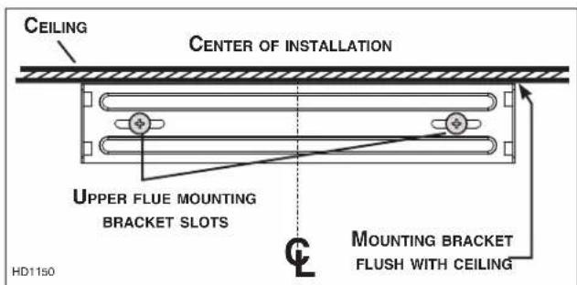
4. INSTALL UPPER FLUE MOUNTING BRACKET (DUCTED INSTALLATION ONLY)
Center the upper flue mounting bracket with the center line previously drawn in step 3 and place it flush with the ceiling. Use the upper flue mounting bracket as a template to mark the position of its screws.
Secure the upper flue mounting bracket to the wall using 2 #8 x 1-1/2" Phillips flat head screws. Make sure that the bracket is tight against the wall.
text_image
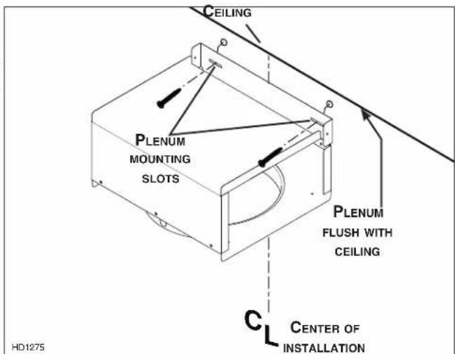
CEILING CENTER OF INSTALLATION UPPER FLUE MOUNTING BRACKET SLOTS HD1150 MOUNTING BRACKET FLUSH WITH CEILING5. INSTALL PLENUM (NON-DUCTED INSTALLATION ONLY)
Center the plenum with the center line previously drawn in step 3 and place it flush with the ceiling. Use the plenum mounting slots as a template to mark the position of its screws.
Secure the plenum to the wall using 2 #8 x 1-1/2" Phillips flat head screws. Make sure that the plenum is tight against the wall.
text_image
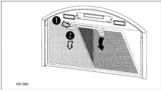
CEILING PLENUM MOUNTING SLOTS PLENUM FLUSH WITH CEILING C CENTER OF INSTALLATION HD12756. REMOVE GREASE FILTER(S)
Lay the back side of the hood flat on a table. Use a piece of cardboard to avoid damaging the table or the hood.
To remove the grease filters, push the filter latch down and tilt each filter downward. Set filters aside.
text_image
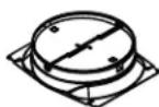
1 2 HD1269Install the damper using 4 M4 x 8 Phillips round head screws.
natural_image
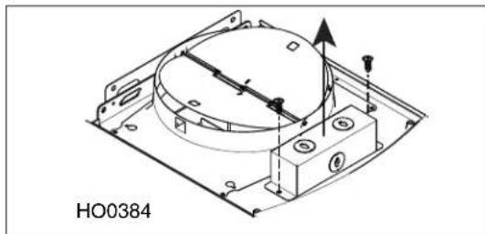
Technical diagram of a mechanical assembly with mounting holes and a central circular component (no text or symbols)Detach the junction box cover from the top of the hood by removing both retaining screws. Set aside the cover and the screws.
natural_image
Technical line drawing of a mechanical assembly with mounting holes and a central circular component (no text or symbols)7. INSTALL THE HOOD
WARNING
BE CAREFUL when installing the decorative flue and hood, they may have sharp edges.
- Align the hood and center it above the hood mounting bracket. Gently lower the hood until it securely engages the bracket.
- Level the hood.
- With the hood hanging in place, mark the four hole locations on wall (see illustration at right).
-
Remove the hood.
-
Drill through marked holes on wall using a 3/32" drill bit.
-
Hang the hood to the wall bracket.
-
Secure the hood to the wall using 2 #8 x 1-1/2" Phillips flat head screws for top holes. Use 2 washers and 2 #8 x 1-1/2" Phillips flat head screws for bottom holes.
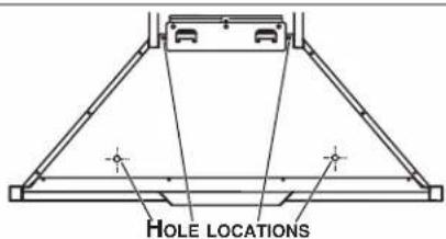
text_image
HOLE LOCATIONS8. CONNECT WIRING
WARNING
Risk of electric shock. Electrical wiring must be done by qualified personnel in accordance with all applicable codes and standards. Before connecting wires, switch power off at service panel and lock service disconnecting means to prevent power to be switched on accidentally.
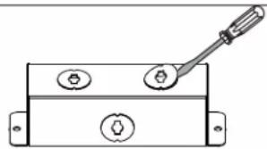
Remove a knockout from the junction box cover top previously set aside.
natural_image
Technical line drawing of a mechanical switch with three circular components and a handle (no text or symbols)HR0226
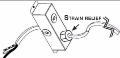
Install a UL approved strain relief (not included) on the house power cable at 4" from the cable end. Run the power cable in the junction box cover opening, then use the strain relief to secure the house power cable to the junction box cover.
text_image
STRAIN RELIEFHD1157
Connect power cable to range hood wiring using included wire connectors. Connect BLACK to BLACK, WHITE to WHITE and GREEN or BARE WIRE to GREEN. DO NOT FORGET TO CONNECT THE GROUND.
Reinstall the junction box cover. Make sure all wires are inside the junction box cover.
natural_image
Technical line drawing of a mechanical assembly with no visible text or symbolsCAUTION
Make sure not to pinch any wire when reinstalling the junction box cover.
9. DUCT CONNECTION
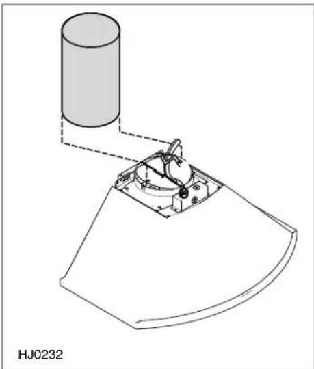
VERTICALLY DUCTED INSTALLATION:
Slide a 8" round metal duct section over the adapter/damper on the hood up to the roof cap. Use metal foil duct tape to seal the joint.
natural_image
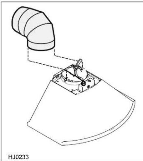
Technical line drawing of a mechanical assembly with a cylindrical component and base plate (no text or symbols)HORIZONTALLY DUCTED INSTALLATION:
Measure and install 8" round metal ductwork to wall cap and 90° elbow over duct collar then install the 90° elbow over the adapter/damper on the hood. Use metal foil duct tape to seal the joints.
natural_image
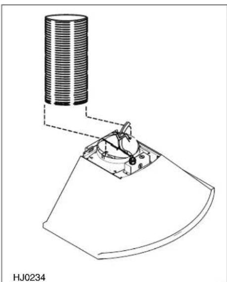
Technical line drawing of a mechanical component with curved surfaces and a central hub (no text or symbols)NON-DUCTED INSTALLATION:
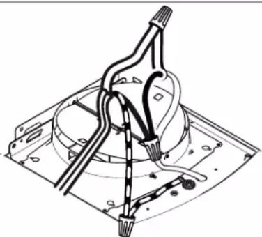
Remove the damper flaps. Measure the length of 8" round flexible duct (included in the non-duct kit) required from the top of the hood to the plenum. Slide the 8" round flexible metal duct over the adapter on the hood. Use metal foil duct tape to seal the joint.
natural_image
Technical line drawing of a mechanical component with a cylindrical component mounted on a base, labeled HJ0234 (no text or symbols on the diagram itself)10. PREPARE THE DECORATIVE FLUE
CAUTION
DO NOT REMOVE the protective plastic film covering the upper flue yet.
NOTE: Both lower and upper flues are included with the hood, but for ceilings of 9 ft. or more, discard the provided lower and upper flues and use the optional flue extension, part no. AEWCN1SS (sold separately).
Remove the upper flue from inside the lower flue. Remove protective plastic film covering the lower flue only.
Peel off both corners at the top of the upper flue.
NOTE: For non-ducted installation only, remove enough plastic film to clear the louvers.
Gently slide upper flue inside lower flue, louvers end up.
NOTE: Upper flue can be reversed to hide louvers in some applications depending on installation heights.
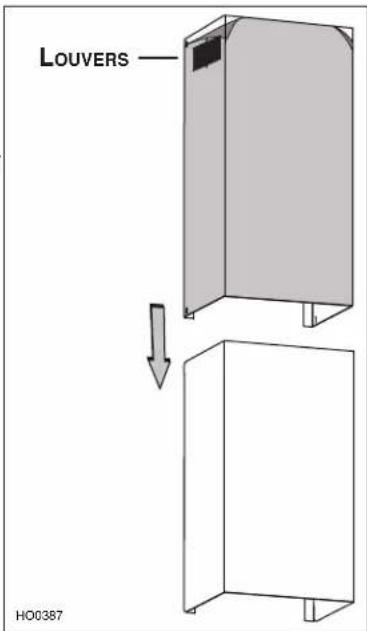
text_image
LOUVERS HO038711. INSTALL THE DECORATIVE FLUE
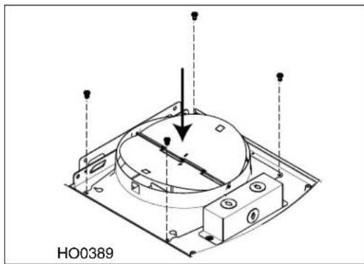
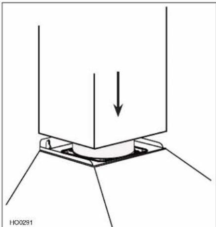
Carefully slide in place decorative flue base in the groove on the top of the hood.
natural_image
Technical diagram showing a mechanical component with a downward arrow indicating force or direction (no text or symbols present)11. INSTALL THE DECORATIVE FLUE (CONTINUED)
NON-DUCTED INSTALLATION:
Slide up the upper flue until it is aligned with the plenum. Secure the upper flue to the plenum using 2 M4 x 12 Phillips round head screws.
Remove protective plastic film covering the upper flue and the hood.
natural_image
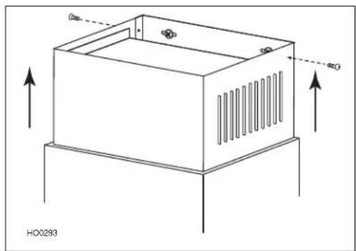
Technical line drawing of a rectangular enclosure with ventilation grilles and directional arrows indicating movement (no text or symbols)DUCTED INSTALLATION:
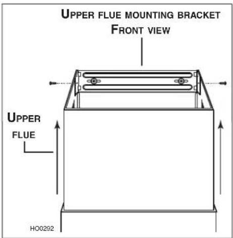
Slide up the upper flue until it is aligned with its mounting bracket. The bracket must be inside the flue. Secure the upper flue to its bracket using 2 M4 x 12 Phillips round head screws.
NOTE: Duct not shown in illustration to ease understanding.
Remove protective plastic film covering the upper flue and the hood.
text_image
UPPER FLUE MOUNTING BRACKET FRONT VIEW UPPER FLUE HO029212. REINSTALL GREASE FILTERS
NON-DUCTED INSTALLATION:
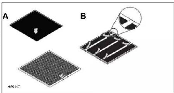
Install a charcoal filter on each aluminum grease filter back (A). Hold the charcoal filter in place by inserting both ends of the 3 metal strips in each aluminum grease filter frame (B).
natural_image
Three-panel diagram showing a microfabricated device with a downward arrow, alongside a close-up of its internal structure (no text or symbols)ALL INSTALLATIONS:
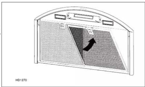
To reinstall the grease filters, align rear filter tabs with slots in the hood. Push each filter into position. Make sure filters are securely engaged after installation.
natural_image
Diagram of a device with mesh panel and directional arrow, no readable text or symbols13. OPERATION
Always turn your hood on before you begin cooking to establish an air flow in the kitchen. Let the blower run for a few minutes to clear the air after you turn off the range. This will help keep the whole kitchen cleaner and fresher.
Operate the hood as follows:
text_image
1 2 3 4 ...
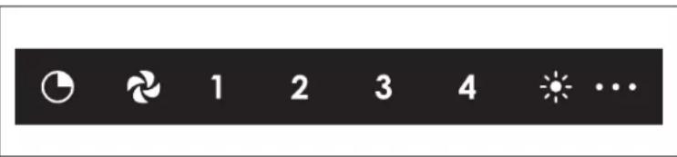
DELAY OFF BUTTON
When activated, the icon lights up and blower current speed remains active for 10 min, then the blower turns off. Blower speed can be changed within the 10 min delay.
To deactivate the delay off function, press on the delay off button.

BLOWER BUTTON
When activated, the icon lights up and the blower turns on at the last saved speed. If there was no speed saved, the blower will be set at speed 1.
To change the blower speed, press on the desired speed button 1, 2, 3 or 4. The current speed button will light up.
To turn off the blower, press on the blower button or press on the current speed button activated.

LIGHT BUTTON
When activated, the icon lights up as well as the dot(s) at the right of the icon that represent(s) the light intensity. By pressing once on the icon, the first dot will light on. By pressing twice on the icon, the first and the second dots will light on. By pressing three times on the icon, all three dots will light on.
To turn off the light, press a fourth time on the button.
14. CARE
Grease Filters
Grease filters should be cleaned frequently. Use a warm dishwashing detergent solution. Grease filters are dishwasher safe.
Clean all-metal filters in the dishwasher using a non-phosphate detergent. Discoloration of the filters may occur if using phosphate detergents, or as a result of local water conditions - but this will not affect filter performance. This discoloration is not covered by the warranty.
Non-ducted Filters
Change the non-duct recirculation filters every 6 months.
Hood Cleaning
Do:
- Regularly wash with clean cloth or rag soaked with warm water and mild soap or liquid dish detergent.
• Always clean in the direction of original polish lines. - Always rinse well with clear water (2 or 3 times) after cleaning. Wipe dry completely.
- You may also use a specialized household stainless steel cleaner.
Don't:
- Use any steel or stainless steel wool or any other scrapers to remove stubborn dirt.
- Use any harsh or abrasive cleansers.
- Allow dirt to accumulate.
- Let plaster dust or any other construction residues reach the hood. During construction/renovation, cover the hood to make sure no dust sticks to stainless steel surface.
Avoid when choosing a detergent:
- Any cleaners that contain bleach will attack stainless steel.
- Any products containing: chloride, fluoride, iodide, bromide will deteriorate surfaces rapidly.
- Any combustible products used for cleaning such as acetone, alcohol, ether, benzol, etc., are highly explosive and should never be used close to a range.
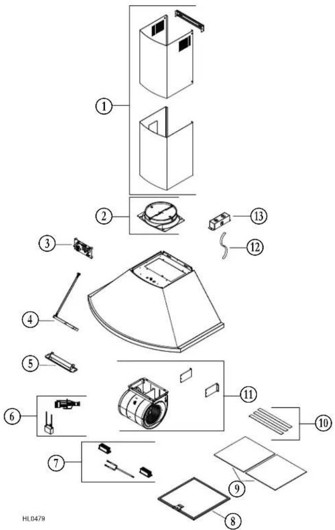
15. REPLACEMENT PARTS
text_image
Exploded view diagram of a refrigerator with numbered parts for identification and assembly reference.REPLACEMENT PARTS AND REPAIRS
In order to ensure your unit remains in good working condition, you must use Broan-NuTone genuine replacement parts only. Broan-NuTone genuine replacement parts are specially designed for each unit and are manufactured to comply with all the applicable certification standards and maintain a high standard of safety. Any third party replacement part used may cause serious damage and drastically reduce the performance level of your unit, which will result in premature failing. Broan-NuTone recommends to contact a certified service depot for all replacement parts and repairs.
| KEY NO. | PART NO. | DESCRIPTION | 30" and 36" |
| 1 | S97021513 | DECORATIVE UPPER AND LOWER FLUES WITH BRACKET | 1 |
| 2 S99528418 DAMPER ASSEMBLY 1 | |||
| 3 S97021516 ELECTRONIC BOARD 1 | |||
| 4 S97021514 USER INTERFACE 1 | |||
| 5 | S97021515 | USER INTERFACE MOUNTING BRACKET | 1 |
| 6 S99271697 C | APACITOR AND MAIN HARNESS ASSEMBLY | 1 | |
| 7 S99271698 LED | MODULES (SET OF 2) 1 | ||
| 8 S99528414 A | LUMINUM GREASE FILTER (SOLD BY PIECE) | 2 | |
| 9 | S99010512 | NON-DUCT RECIRCULATION FILTERS (SET OF 2) (METAL STRIPS NOT INCLUDED) | 1 |
| 10 | S99010513 | METAL STRIPS FOR NON-DUCT RECIRCULATION FILTER S99010512 (SET OF 3) | 2 |
| 11 | S99528407 | MOTOR AND BLOWER ASSEMBLY | 1 |
| 12 | S99271696 | POWER CABLE | 1 |
| 13 | S99840026 | JUNCTION BOX | 1 |
| * | S97021512 | PARTS BAG INCLUDING: 9 #8 x 1-1/2" PHILLIPS FLAT HEAD SCREWS,2 M4 x 12 PHILLIPS ROUND HEAD SCREWS, 4 M4 x 8 PHILLIPS ROUND HEADSCREWS, 2 WASHERS, 3 WIRE CONNECTORS, 1 UPPER FLUE MOUNTING BRACKET AND1 HOOD MOUNTING BRACKET | 1 |
* NOT SHOWN.
FIVE-YEAR LIMITED WARRANTY FOR BEST® PRODUCTS
Warranty Period and Exclusions: Broan-NuTone, LLC (the "Company") warrants to the consumer purchaser of its product ("you") that the product (the "Product") will be free from material defects in the materials or its workmanship for a period of five (5) years from the date of original purchase (or such longer period as may be required by applicable law) or a period of two (2) years from the date of service for any labor provided on the Product.
The limited warranty period for any replacement parts provided by the Company and for any Products repaired or replaced under this limited warranty shall be the remainder of the original warranty period (or such longer period as may be required by applicable law).
THIS WARRANTY DOES NOT EXTEND TO FLUORESCENT LAMP STARTERS, TUBES AND BULBS, FUSES, FILTERS, DUCTS, ROOF CAPS, WALL CAPS AND OTHER ACCESSORIES FOR DUCTING. This warranty does not cover (a) normal maintenance and service, (b) normal wear and tear, (c) any Products or parts which have been subject to misuse, abuse, abnormal usage, negligence, accident, improper or insufficient maintenance, storage or repair (other than repair by the Company), (d) damage caused by faulty installation, or installation or use contrary to recommendations or instructions, (f) damage caused by exposure to salt air, (g) damage in transit, (h) natural wear of finish, (i) Products in commercial or nonresidential use, (j) damage caused by fire, flood or other act of God, or (k) Products with altered, defaced or removed serial numbers. This warranty covers only Products sold to consumers in North America. This warranty supersedes all prior warranties and, subject to applicable law, is not transferable from the original consumer purchaser.
No Other Warranties: This Limited Warranty contains the Company's sole obligation and your sole remedy for defective Products. The foregoing warranties are exclusive and in lieu of any other warranties and conditions, express or implied. TO THE MAXIMUM EXTENT PERMITTED BY APPLICABLE LAW, THE COMPANY DISCLAIMS AND EXCLUDES ALL OTHER EXPRESS WARRANTIES AND CONDITIONS, AND DISCLAIMS AND EXCLUDES ALL WARRANTIES AND CONDITIONS IMPLIED BY LAW, INCLUDING WITHOUT LIMITATION THOSE OF MERCHANTABILITY AND FITNESS FOR A PARTICULAR PURPOSE.
To the extent that applicable law prohibits the exclusion of implied warranties or conditions, the duration of any applicable implied warranty or condition is limited to the period specified for the express warranty above. Some jurisdictions (which may include the Province of Quebec or specific US states) do not allow limitations on how long an implied warranty lasts, so the above limitation may not apply to you. Any oral or written description of the Product is for the sole purpose of identifying it and shall not be construed as an express warranty.
Whenever possible, each provision of this Limited Warranty shall be interpreted in such manner as to be effective and valid under applicable law, but if any provision is held to be prohibited or invalid, such provision shall be ineffective only to the extent of such prohibition or invalidity, without invalidating the remainder of such provision or the other remaining provisions of the Limited Warranty.
Remedy: During the applicable limited warranty period, the Company will, at its option, provide replacement parts for, or repair or replace, without charge, any Product or part thereof, to the extent the Company finds it to be covered by and in breach of this limited warranty under normal use and service. The Company will ship the repaired or replaced Product or replacement parts to you at no charge. You are responsible for all costs for removal, reinstallation and shipping, insurance or other freight charges incurred in the shipment of the Product or part to the Company. If you must send the Product or part to the Company, as instructed by the Company, you must properly pack the Product or part—the Company is not responsible for damage in transit. The Company reserves the right to utilize reconditioned, refurbished, repaired or remanufactured Products or parts in the warranty repair or replacement process. Such Products and parts will be comparable in function and performance to an original Product or part and warranted for the remainder of the original warranty period (or such longer period as may be required by applicable law).
Company reserves the right, in its sole discretion, to refund the money actually paid by you for the Product. If the Product or component is no longer available, replacement may be made with a similar product of equal or greater value, at Company's sole discretion. This is your sole and exclusive remedy for breach of this limited warranty.
Exclusion of Damages: THE COMPANY'S OBLIGATION TO PROVIDE REPLACEMENT PARTS, OR REPAIR OR REPLACE, AT THE COMPANY'S OPTION, SHALL BE YOUR SOLE AND EXCLUSIVE REMEDY UNDER THIS LIMITED WARRANTY AND THE COMPANY'S SOLE AND EXCLUSIVE OBLIGATION. THE COMPANY SHALL NOT BE LIABLE FOR INCIDENTAL, INDIRECT, CONSEQUENTIAL OR SPECIAL DAMAGES ARISING OUT OF OR IN CONNECTION WITH THE PRODUCT, ITS USE OR PERFORMANCE.
Some jurisdictions do not allow the exclusion or limitation of incidental or consequential damages, so the above limitation or exclusion may not apply to you. This warranty gives you specific legal rights, and you may also have other rights, which vary from jurisdiction to jurisdiction. The disclaimers, exclusions, and limitations of liability under this warranty will not apply to the extent prohibited by applicable law.
This warranty covers only replacement or repair of defective Products or parts thereof at the Company's main facility and does not include the cost of field service travel and living expenses.
Any assistance the Company provides to or procures for you outside the terms, limitations or exclusions of this limited warranty will not constitute a waiver of such terms, limitations or exclusions, nor will such assistance extend or revive the warranty. The Company will not reimburse you for any expenses incurred by you in repairing or replacing any defective Product, except for those incurred with the Company's prior written permission.
How to Obtain Warranty Service: To qualify for warranty service, you must (a) notify the Company at the address or telephone number stated below within seven (7) days of discovering the covered defect, (b) give the model number and part identification and (c) describe the nature of any defect in the Product or part. At the time of requesting warranty service, you must present evidence of the original purchase date. If you cannot provide a copy of the original written limited warranty, then the terms of the Company's most current written limited warranty for your particular product will control.
PRODUCT SPECIFICATIONS
All illustrations and specifications in this catalog are based on the latest product information available at time of production. Broan-NuTone, LLC and BEST® reserves the right to make changes at any time, without notice, in prices, colors, materials, equipment, specifications and models, place of manufacture and to discontinue models or equipment.
Best
Broan-NuTone, LLC- 926 W. State Street, Hartford, WI 53207 1-800-637-1453
Best®, 550 Lemire Blvd., Drummondville, QC, Canada (1-866-737-7770) www.bestrangehoods.com
best®
natural_image
Isometric line drawing of a mechanical component with a curved base and top opening (no text or symbols)SÉRIE WCN1
⚠️CONÇUE UNIQUEMENT POUR LA CUISSON DOMESTIQUE △
LIRE ET CONSERVER CES DIRECTIVES
INSTALLATEUR: LAISSER CE GUIDE AU PROPRIÉTAIRE.
PROPRIÉTAIRE: DIRECTIVES D'UTILISATION ET D'ENTRETIEN EN PAGE 10.
BEST; Hartford, Wisconsin www.BestRangeHoods.com 800 558-1711
BEST; Drummondville, QC, Canada www.BestRangeHoods.ca 866 737-7770
natural_image
Isometric line drawing of a rectangular box with a recessed top (no text or symbols)(1) ENSEMBLE DE CONDUIT DÉCORATIF
(1) SUPPORT DE MONTAGE DU CONDUIT DÉCORATIF SUPÉRIEUR
2.2 INSTALLATION AVEC CONDUITS
natural_image
Technical diagram of a mechanical assembly with mounting holes and a central circular component (no text or symbols)natural_image
Technical line drawing of a mechanical assembly with mounting holes and a central circular component (no text or symbols)7. INSTALLER LA HOTTE
⚠ AVERTISSEMENT
natural_image
Technical line drawing of a mechanical component with a lever and three circular holes (no text or symbols)HR0226
text_image
SERRE-CÂBLE HD457HD1157
natural_image
Technical line drawing of a mechanical assembly with wires and components (no text or symbols)ATTENTION
natural_image
Technical line drawing of a mechanical assembly with a cylindrical component and a base plate (no text or symbols)INSTALLATION EN ÉVACUATION HORIZONTALE :
natural_image
Technical line drawing of a mechanical component with a curved duct and base plate (no text or symbols)INSTALLATION EN RECIRCULATION :
natural_image
Technical line drawing of a mechanical component with a cylindrical component and base plate (no text or symbols)10. PRÉPARER LE CONDUIT DÉCORATIF
ATTENTION
text_image
FENTES HO038711. INSTALLER LE CONDUIT DÉCORATIF
natural_image
Diagram showing a mechanical component with a downward arrow and base, labeled HO0291 (no text or symbols on the diagram itself)11. INSTALLER LE CONDUIT DÉCORATIF (SUITE)
INSTALLATION EN RECIRCULATION :
natural_image
Technical line drawing of a rectangular enclosure with ventilation grilles and directional arrows indicating movement (no text or symbols)INSTALLATION AVEC CONDUITS:
natural_image
Three-panel diagram showing a microfabricated device (A), its internal structure, and a close-up of a microfabricated component (B), with no visible text or symbols.natural_image
Diagram of a device with mesh panel and directional arrow, no readable text or symbols13. FONCTIONNEMENT
text_image
Sequence of icons including refresh, rotate, and sun symbols on a black background
BOUTON ARRÊT DIFFÉRÉ
text_image
Exploded diagram of a device with numbered parts, likely for assembly or manufacturing purposes.PIÈCES DE REMPLACEMENT ET SERVICE
SPÉCIFICATIONS DU PRODUIT
Broan-NuTone LLC : 926 W. State Street, Hartford (WI) 53207 1 800 637-1453
Best ^MD , 550, boul. Lemire, Drummondville (Québec), Canada (1 866 737-7770) fr.bestrangehoods.ca
natural_image
Isometric line drawing of a mechanical component with a curved base and top opening (no text or symbols)SERIE WCN1
⚠DESTINADA ÚNICAMENTE PARA COCINAS DOMÉSTICAS
LEA ESTAS INSTRUCCIONES Y GUÁRDELAS
INSTALADOR: DEJE ESTE MANUAL AL PROPIETARIO.
BEST; Drummondville, QC, Canada www.BestRangeHoods.ca 866 737-7770
natural_image
Isometric line drawing of a rectangular box with a U-shaped top and side window (no text or symbols)(1) CONJUNTO DE LA CHIMENEA DECORATIVA
(1) SOPORTE DE MONTAJE DE LA PARTE SUPERIOR DE LA CHIMENEA
(2) FILTROS DE GRASA

(9) TORNILLOS #8 X 1-1/2 PULG. PHILLIPS DE CABEZA PLANA

(1) SOPORTE DE MONTAJE DE LA CAMPANA

(2) TORNILLOS M4 x 12 PHILLIPS DE CABEZA REDONDA

(4) TORNILLOS M4 x 8 PHILLIPS DE CABEZA REDONDA

(2) ARANDELAS

(3) CONECTADORES
(1) COMPUERTA
HR0266E
natural_image
Technical line drawing of a mechanical assembly with mounting holes and a central circular component (no text or symbols)natural_image
Technical line drawing of a mechanical assembly with mounting brackets and a central circular component (no text or symbols)7. INSTALE LA CAMPANA
ADVERTENCIA
natural_image
Technical line drawing of a mechanical component with a lever and three circular holes (no text or symbols)HR0226
natural_image
Technical line drawing of a mechanical assembly with wires and components (no text or symbols)PRECAUCIÓN
natural_image
Technical line drawing of a mechanical assembly with a cylindrical component and base mount (no text or symbols)natural_image
Technical line drawing of a mechanical component with a curved pipe and base plate (no text or symbols)natural_image
Technical line drawing of a mechanical component with a cylindrical component and base plate (no text or symbols)10. PREPARE LA CHIMENEA DECORATIVA
PRECAUCIÓN
natural_image
Diagram showing a mechanical component with a downward arrow and base, labeled HO0291 (no text or symbols on the diagram itself)natural_image
Technical line drawing of a rectangular enclosure with ventilation grilles and directional arrows indicating airflow or movement (no text or symbols)natural_image
Three-panel diagram showing a microfabricated device (A), its internal structure, and a close-up of a microfabricated component (B), with no visible text or symbols.natural_image
Diagram of a device casing with mesh pattern and directional arrow, no readable text or symbols13. FUNCIONAMIENTO
text_image
Sequence of icons on a black background, including refresh, rotate, and star symbols with numeric labels 1 to 4
text_image
Exploded view diagram of a refrigerator with numbered parts for identification and assembly reference.Broan-NuTone, LLC: 926 W. State Street, Hartford, WI 53207 1 800 637-1453
Best®, 550, boul. Lemire, Drummondville (Québec), Canada (1 866 737-7770) www.bestrangehoods.com