CC65I28SB - Basket BEST - Free user manual and instructions
Find the device manual for free CC65I28SB BEST in PDF.

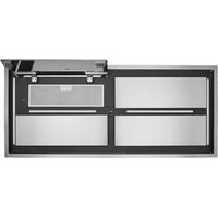
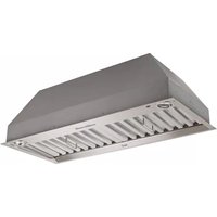
| Product Type | Built-in Hood |
| Brand | Best |
| Model | CC65I28SB |
| Weight | 33 lb (15 kg) |
| Nominal Width | 28 1/8 in (71.4 cm) |
| Depth | 13 1/4 in (33.7 cm) |
| Height (body) | 10 1/2 in (26.7 cm) |
| Power Supply | 120 V~, 60 Hz |
| Ventilation Type | Ducted (3 1/4 in x 10 in) |
| Maximum Airflow | 600 cfm (single fan) |
| Number of Speeds | 4 (low to high) |
| Delayed Shut-off Function | Yes, 5 minutes |
| Heat Sentry Device | Yes, protection against excessive heat |
| Lighting | 2 LED modules, 2 levels (high/low) |
| Filter Type | Metal, dishwasher-safe |
| Number of Filters | 2 |
| Minimum Distance Above Electric Range | 24 in (61 cm) |
| Minimum Distance Above Gas Range | 30 in (76 cm) |
| Material | Stainless Steel |
| Cleaning | Soft cloth, warm water and mild soap |
| Warranty | 5 years limited |
| Replacement Parts | Original Broan-NuTone recommended |
| Repairability | Qualified professional required |
| Usage | Domestic, indoor only |
| Installation | Built-in into cabinet, two installers recommended |
Frequently Asked Questions - CC65I28SB BEST
User questions about CC65I28SB BEST
0 question about this device. Answer the ones you know or ask your own.
Ask a new question about this device
Download the instructions for your Basket in PDF format for free! Find your manual CC65I28SB - BEST and take your electronic device back in hand. On this page are published all the documents necessary for the use of your device. CC65I28SB by BEST.
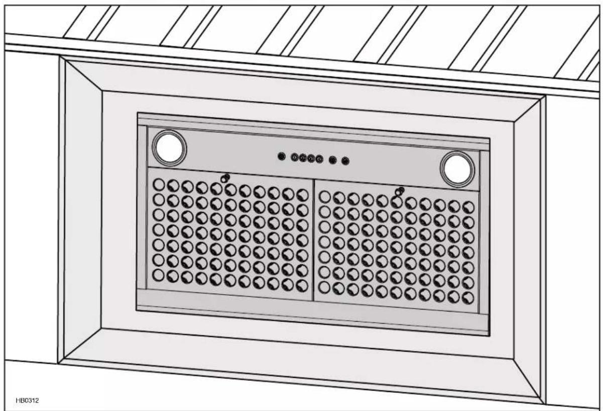
USER MANUAL CC65I28SB BEST
natural_image
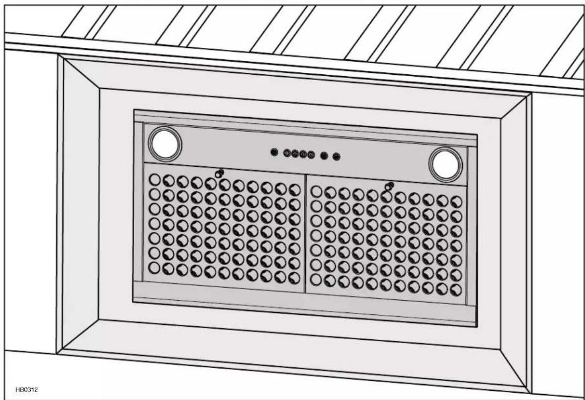
Technical line drawing of a cabinet or enclosure with circular components and ventilation grilles (no text or symbols)CC6 SERIES
READ AND SAVE THESE INSTRUCTIONS
INSTALLER: LEAVE THIS MANUAL WITH HOMEOWNER.
HOMEOWNER: USE AND CARE INFORMATION ON PAGES 12 AND 13.
BEST; Hartford, Wisconsin www.BestRangeHoods.com 800-558-1711
BEST; Drummondville, QC, Canada www.BestRangeHoods.ca 866-737-7770

text_image
7 7 2 3 7 1 1 5 4 4 0 7TO REDUCE THE RISK OF FIRE, ELECTRIC SHOCK OR INJURY TO PERSONS, OBSERVE THE FOLLOWING:
- Use this unit only in the manner intended by the manufacturer. If you have questions, contact the manufacturer at the address or telephone number listed in the warranty.
- Before servicing or cleaning unit, switch power off at service panel and lock service disconnecting means to prevent power from being switched on accidentally. When the service disconnecting means cannot be locked, securely fasten a prominent warning device, such as a tag, to the service panel.
- Installation work and electrical wiring must be done by qualified personnel in accordance with all applicable codes and standards, including fire-rated construction codes and standards.
- Sufficient air is needed for proper combustion and exhausting of gases through the flue (chimney) of fuel burning equipment to prevent backdrafting. Follow the heating equipment manufacturer's guidelines and safety standards such as those published by the National Fire Protection Association (NFPA) and the American Society for Heating, Refrigeration and Air Conditioning Engineers (ASHRAE) and the local code authorities.
- When cutting or drilling into wall or ceiling, do not damage electrical wiring and other hidden utilities.
- Ducted fans must always be vented outdoors.
- To reduce the risk of fire or electric shock, do not use this unit with any additional solid-state speed control device.
- To reduce the risk of fire, use only metal ductwork.
- This unit must be grounded.
- When applicable local regulations comprise more restrictive installation and/or certification requirements, the aforementioned requirements prevail on those of this document and the installer agrees to conform to these at his own expenses.
TO REDUCE THE RISK OF A RANGE TOP GREASE FIRE:
a) Never leave surface units unattended at high settings. Boilovers cause smoking and greasy spillovers that may ignite. Heat oils slowly on low or medium settings.
b) Always turn hood ON when cooking at high heat or when flambeing food (i.e.: Crêpes Suzette, Cherries Jubilee, Peppercorn Beef Flambé).
c) Clean ventilating fans frequently. Grease should not be allowed to accumulate on fan, filters or in exhaust ducts.
d) Use proper pan size. Always use cookware appropriate for the size of the surface element.
WARNING
TO REDUCE THE RISK OF INJURY TO PERSONS IN THE EVENT OF A RANGE TOP GREASE FIRE, OBSERVE THE FOLLOWING\*:
- SMOTHER FLAMES with a close-fitting lid, cookie sheet or metal tray, then turn off the burner. BE CAREFUL TO PREVENT BURNS. IF THE FLAMES DO NOT GO OUT IMMEDIATELY, EVACUATE AND CALL THE FIRE DEPARTMENT.
- NEVER PICK UP A FLAMING PAN — You may be burned.
- DO NOT USE WATER, including wet dishcloths or towels — This could cause a violent steam explosion.
- Use an extinguisher ONLY if:
A. You own a Class ABC extinguisher and you know how to operate it.
B. The fire is small and contained in the area where it started.
C. The fire department has been called.
D. You can fight the fire with your back to an exit.
* Based on "Kitchen Fire Safety Tips" published by NFPA.
CAUTION
- For indoor use only.
- For general ventilating use only. Do not use to exhaust hazardous or explosive materials and vapors.
- To avoid motor bearing damage and noisy and/or unbalanced impellers, keep drywall spray, construction dust, etc. off power unit.
- Your power pack motor(s) has a thermal overload which will automatically shut off the motor(s) if it overheats. The motor(s) will restart when cooled down. If the motor(s) continues to shut off and restart, have the power pack serviced.
- The minimum hood distance above cooktop must not be less than 24". A maximum of 30" above cooktop is highly recommended for best capture of cooking impurities. For a gas range, the bottom of the hood MUST NOT BE LESS than 30" above cooktop.
- Two installers are recommended because of the large size and weight of this unit.
- To reduce the risk of fire and to properly exhaust air, be sure to duct air outside — Do not exhaust air into spaces within walls or ceiling or into attics, crawl space or garage.
- Because of the high exhausting capacity of this unit, you should make sure enough air is entering the house to replace exhausted air by opening a window close to or in the kitchen.
- To reduce the risk of fire and electrical shock, the Best CC6 Series models must be installed only with their own built-in blower(s). Other blowers cannot be substituted.
-
Please read specification label on product for further information and requirements.
-
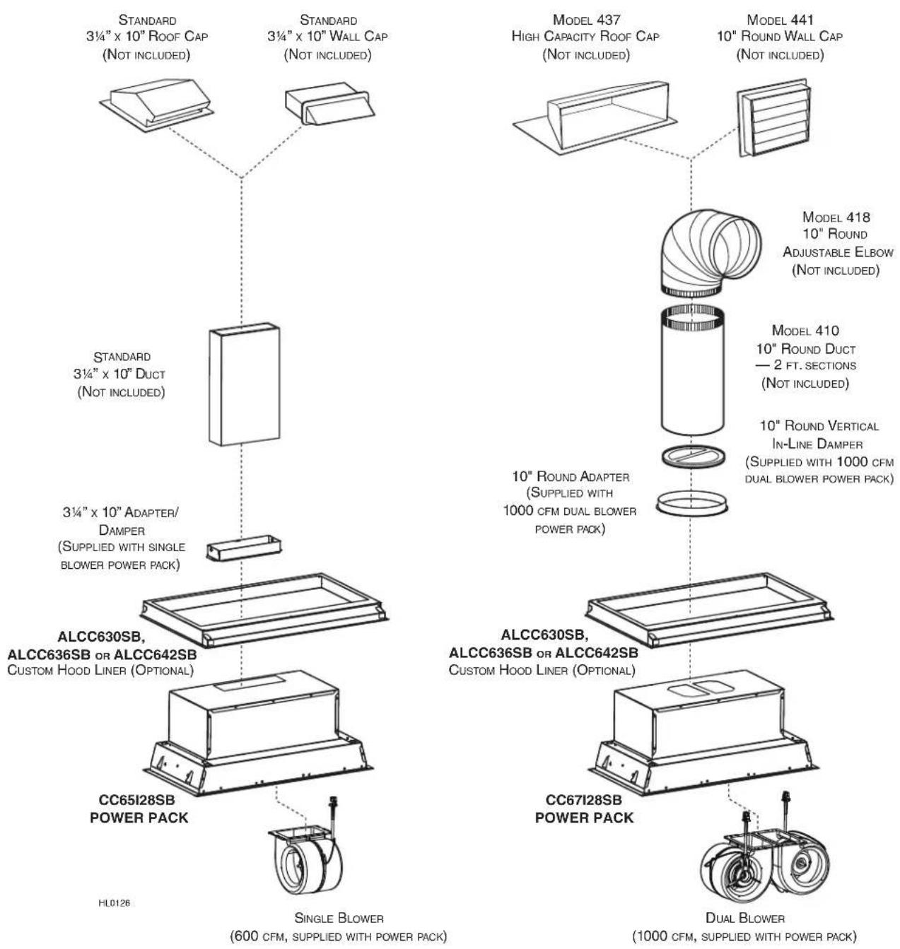
CC6 SERIES POWER PACK SYSTEM -
text_image
STANDARD 3¼" x 10" ROOF CAP (NOT INCLUDED) STANDARD 3¼" x 10" WALL CAP (NOT INCLUDED) MODEL 437 HIGH CAPACITY ROOF CAP (NOT INCLUDED) MODEL 441 10" ROUND WALL CAP (NOT INCLUDED) STANDARD 3¼" x 10" DUCT (NOT INCLUDED) MODEL 418 10" ROUND ADJUSTABLE ELBOW (NOT INCLUDED) MODEL 410 10" ROUND DUCT — 2 FT. SECTIONS (NOT INCLUDED) 10" ROUND VERTICAL In-Line DAMPER (SUPPLIED WITH 1000 CFM DUAL BLOWER POWER PACK) ALCC630SB, ALCC636SB OR ALCC642SB CUSTOM HOOD LINER (OPTIONAL) ALCC630SB, ALCC636SB OR ALCC642SB CUSTOM HOOD LINER (OPTIONAL) CC65I28SB POWER PACK HL0126 SINGLE BLOWER (600 CFM, SUPPLIED WITH POWER PACK) DUAL BLOWER (1000 CFM, SUPPLIED WITH POWER PACK)1. PREPARE THE INSTALLATION
WARNING
When performing installation, servicing or cleaning the unit, it is recommended to wear safety glasses and gloves.
NOTE: Before proceeding to the installation, check the contents of the box. If items are missing or damaged, contact the manufacturer.
Make sure that the following items are included:
- Power Pack
- Accessories: • 2 Filters
• 2 Filter knobs with screws, taped inside power pack
- 3 14'' x 10" adapter/damper (supplied with 600 CFM single blower power pack)
- 10" round in-line vertical damper (supplied with 1000 CFM dual blower power pack)
- 10" round adapter (supplied with 1000 CFM dual blower power pack)
- Bag of parts including: 1 wire clamp, 2 wire connectors, 4 no. 8 x 3/8" screws, 9 no. 8 x 1/2" chrome plated screws, 10 no. 8-32 x 1/4" screws. If need be, discard extra hardware.
Parts sold separately:
- Custom hood liner model ALCC630SB, ALCC636SB or ALCC642SB (optional)
- Ducts, elbows, wall and roof caps. Refer to page 3 for a complete list of venting options and model numbers.
NOTE: During installation, protect countertop and/or cooktop.
2. INSTALL DUCTWORK AND ELECTRICAL WIRING
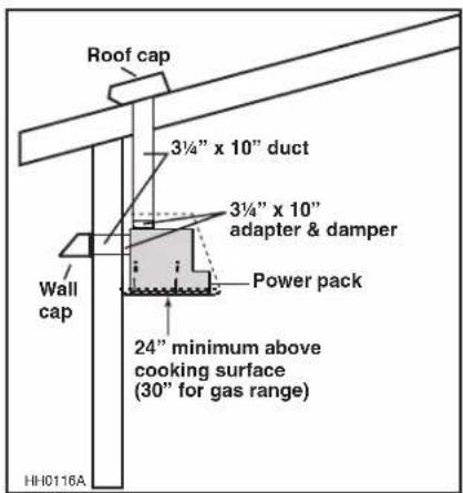
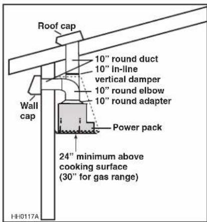
Plan where and how the ductwork will be installed. Access to the top of the power pack is preferred for connection of ductwork. Install proper-sized ductwork, elbows and roof or wall cap for the type of power pack you are installing. If installing CC65I28SB single blower power pack, use 3¼" x 10" ductwork. If installing CC67I28SB double blower power pack, use 10" round ductwork. Use 2" metal foil duct tape to seal duct joints.
We recommend to install the power pack at a minimum distance of 24" from an electric range and 30" from a gas range.
Distances over 30" are at the installer and users discretion.
Run 3-wire power supply cable to installation location. Its length should extend at least 4 feet below the bottom of the custom hood.
text_image
Roof cap 3¼" x 10" duct 3¼" x 10" adapter & damper Power pack Wall cap 24" minimum above cooking surface (30" for gas range) HH0116AMODEL CC65I28SB
(SINGLE BLOWER) TYPICAL DUCTWORK
text_image
Roof cap 10" round duct 10" In-line vertical damper 10" round elbow 10" round adapter Wall cap Power pack 24" minimum above cooking surface (30" for gas range) HH0117AMODEL CC67I28SB
(DUAL BLOWER) TYPICAL DUCTWORK
NOTE: Although the horizontal discharge installation is feasible with CC65I28SB power pack model, this installation type should be performed in specific situation only since it requires particular knowledge and technical skills from the installers.
3. PREPARE CUSTOM HOOD
WARNING
When building a custom hood, always follow all applicable construction codes and standards. The custom hood must be positively secured to wall studs or other wooden framework behind the drywall. Make sure it is capable of supporting its own weight and the weight of the power pack. Failure to do so may cause personal injury or damage to countertop or cooktop.
The custom hood must be constructed to fit the shape and total weight of the CC6 series power pack model. The recommended minimum thickness for the custom hood base is 5/8". If an optional custom hood liner will be installed, we recommend the sides and front of the custom hood to be 3/4" thick. If the optional custom hood liner will not be installed, the custom hood sides and front thickness are at the installer's discretion. See chart and illustration for details.
| POWER PACK MODEL | TOTAL WEIGHT |
| CC65I28SB 33 | LB. |
| CC67I28SB 45 | LB. |
CC65I28SB
text_image
10-1/2" 3/4" 9-3/4" 10-1/8" 7/8" 3-1/4" 1-11/16" 13-5/16" 2-3/4" 9-7/8" 2-15/16" 26-5/8" 28-1/8" 13-1/4" 14-3/4" 1-1/16"CC67I28SB
NOTE: The dual blower model has the same dimensions as the single blower model, but does not have a horizontal discharge.
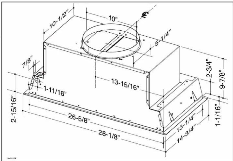
text_image
10-1/2" 10" 5 1/4" 7/8" 1-11/16" 13-15/16" 2-3/4" 9-7/8" 2-15/16" 26-5/8" 28-1/8" 13-1/4" 14-3/4" 1-1/16" HC201A4. INSTALL CUSTOM HOOD LINER (OPTIONAL)
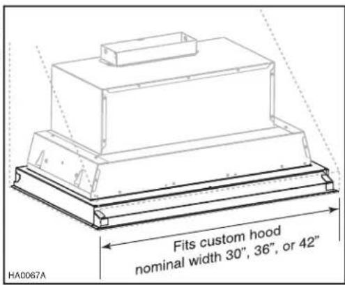
The liners are especially designed to protect the exterior base of the custom hood. Refer to the table below to find the right liner model number according to the width of the custom hood nominal width. To view specific model information, including depths for each liner model, visit www.BestRangeHoods.com, www.BestRangeHoods.ca, or contact Technical Support (phone number listed on front cover).
To install, see instruction packed with custom hood liner.
NOTE: The liner must be installed before the insert.
| LINER MODEL | CUSTOM HOODNORMINAL WIDTH |
| ALCC630SB 30" | |
| ALCC636SB 36" | |
| ALCC642SB 42" |
text_image
Fits custom hood nominal width 30", 36", or 42" HA0067A5. CUT THE HOLE IN CUSTOM HOOD BASE
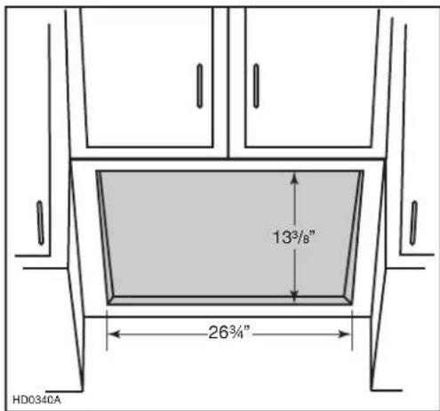
If it is not done yet, cut a hole in the bottom of the custom hood, using the dimensions shown at right.
NOTE: Keep in mind that the unit exterior flange is 3/4".
text_image
13³/8" 26³/4" HD0340A6. REMOVE FILTER
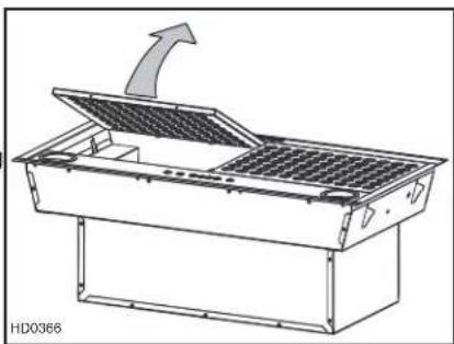
Rest the power pack on a table. Remove tapes on filters. Lift filters from power pack by pushing them towards the back and rotate, then set filters aside.
natural_image
Technical line drawing of a mechanical device with an open lid and internal grid structure, no text or symbols present.7. UNPLUG THE BLOWER(S)
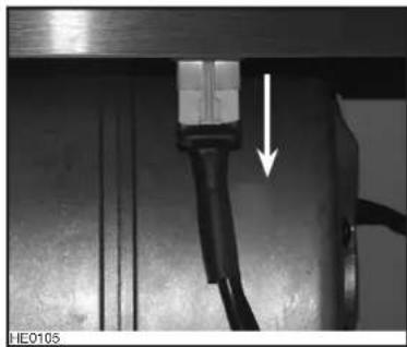
Unplug the blower(s) (one or two, depending on model) from the front panel.
natural_image
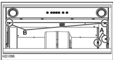
Close-up of a mechanical component with a black cable and arrow indicating a downward motion (no text or symbols visible)8. REMOVE WIRING COVER AND FRONT PANEL
Using a Robertson or a Phillips no.2 screwdriver, remove both wiring cover retaining screws (A). Detach it from the power pack and set aside with its screws. Then, remove both sides screws (B) retaining the front panel to the power pack. Carefully detach the front panel from the power pack and set aside with its screws.
text_image
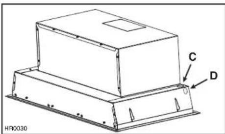
B A HD10989. REMOVE THE ELECTRICAL KNOCKOUT
From inside the power pack, punch out the electrical knockout hole on top right side (C) OR on back right side (D). Install the wire clamp (included in parts bag).
text_image
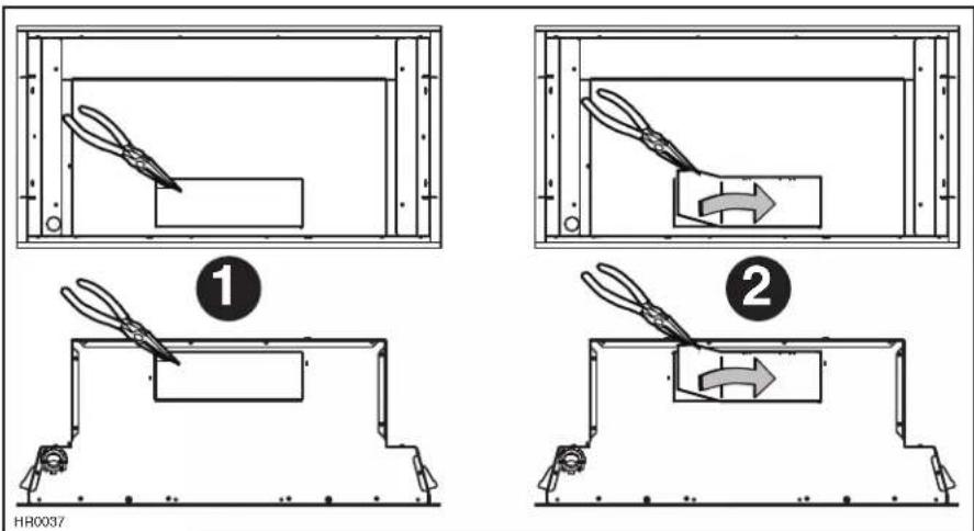
C D HR003010. REMOVE THE KNOCKOUT OPENING (SINGLE BLOWER MODEL ONLY)
Remove the knockout opening on top (vertical discharge installation) or on back (horizontal discharge installation) of the power pack.
text_image
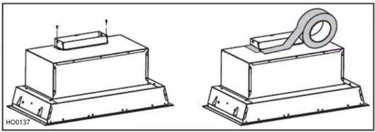
① ② HR003711. INSTALL THE ADAPTER/DAMPER (SINGLE BLOWER MODEL ONLY)
VERTICAL DISCHARGE INSTALLATION
Using 2 no. 8 x 3/8" screws provided in parts bag, secure the adapter/damper to the top of the power pack. Remove tape from damper flap. Seal the adapter to the power pack using metal foil duct tape.
natural_image
Technical line drawings of two mechanical components with mounting bases and a coiled spring (no text or symbols)HORIZONTAL DISCHARGE INSTALLATION
The adapter/damper will be installed on the back of the power pack once the power pack is mounted in the custom hood. Refer to step 15.
12. INSTALL THE ADAPTER AND THE DAMPER (DUAL BLOWER MODEL ONLY)
Using 2 no. 8 x 3/8" screws from parts bag, assemble the adapter on the top of the power pack. Seal all joints with metal foil duct tape to eliminate air leaks.
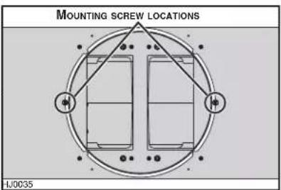
text_image
MOUNTING SCREW LOCATIONS HJ0035Install 10" damper inside the VERTICAL ductwork that will be attached to power pack. Do not install in a horizontal ductwork or it will not open and close properly. Remove shipping tape if present. To optimize airflow and reduce noise, position the damper at least 17" above the top of the double blower power pack; or as far as the duct run will allow. Also, ensure the damper hinge will be parallel to power pack sides (see figure at right). Secure the damper to the duct with 3 no. 8 sheet metal screws (not provided). Ensure damper opens and closes freely. Seal all joints with metal foil duct tape to eliminate air leaks.
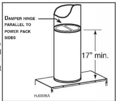
text_image
DAMPER HINGE PARALLEL TO POWER PACK SIDES 17" min. HJ0036A13. REMOVE THE BLOWER (SINGLE BLOWER MODEL, HORIZONTAL DISCHARGE ONLY)
In order to ease the power pack alignment with horizontal ductwork, disassemble the blower from the power pack before installing it in the custom hood.
Using a 5/16" socket, or a Phillips no. 2 or a Robertson no. 2 screwdriver, remove all blower mounting screws from the inner top of the power pack. Set blower and screws aside.
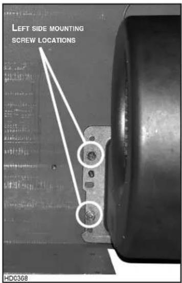
text_image
LEFT SIDE MOUNTING SCREW LOCATIONS HD0368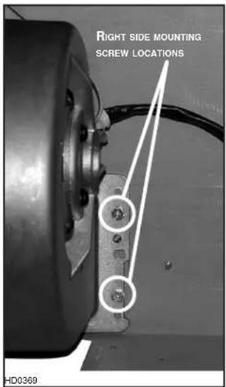
text_image
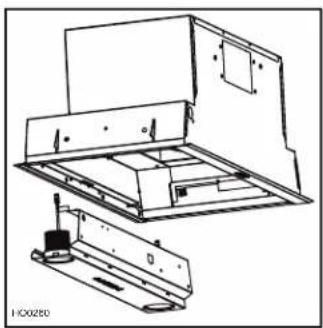
RIGHT SIDE MOUNTING SCREW LOCATIONS HD036914. INSTALL THE POWER PACK
CAUTION
Take care not to kink ducting or pinch electrical cable when installing the power pack.
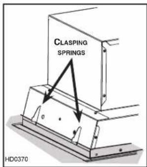
Insert the power pack in the custom hood until the bottom of the clasping springs (2 per side) rests on the top of the custom hood base (grey zone in illustration at right).
text_image
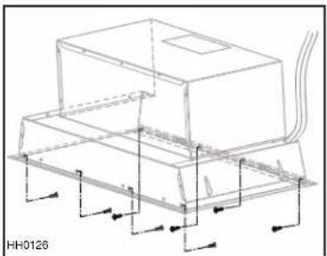
CLASPING SPRINGS HD0370From inside the power pack, using provided no. 8-10 x 1/2" screws, mount the power pack to the custom hood base. To do so, raise the front until its flange rests on the outer side of the custom hood base and use 2 screws to secure in place. Do the same for the back, then complete the installation with 2 additional screws on the front and back. See figure at right for mounting screws locations.
natural_image
Technical line drawing of a mechanical assembly with no visible text or symbolsVERTICAL EXHAUST INSTALLATION ONLY
Ensure the adapter/damper enters the ducting and the damper opens freely. Wherever it is possible, seal connections with metal foil duct tape.
15. INSTALL THE ADAPTER/DAMPER ON BACK OF POWER PACK (SINGLE BLOWER MODEL, HORIZONTAL DISCHARGE ONLY)
From the outside of the wall, using two no. 8 x 3/8" screws provided in parts bag, secure the adapter/damper to the back of the power pack. Remove tape from damper flap. Connect ducting to the adapter/damper and seal the joint using metal foil duct tape.

text_image
HH0127A BACK VIEW SIDE VIEW WALL16. REINSTALL THE BLOWER (SINGLE BLOWER MODEL, HORIZONTAL DISCHARGE ONLY)
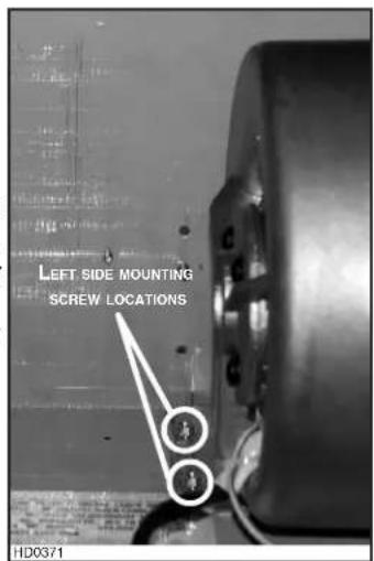
The single blower power pack is factory shipped for a vertical discharge installation. For a horizontal discharge installation, the blower must be flipped. Using a 5/16" socket, or a Phillips or Robertson no. 2 screwdriver, secure the blower to the inner back of the power pack with all blower mounting screws (previously removed in step 13).
text_image
LEFT SIDE MOUNTING SCREW LOCATIONS HD0371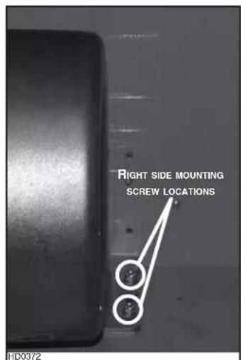
text_image
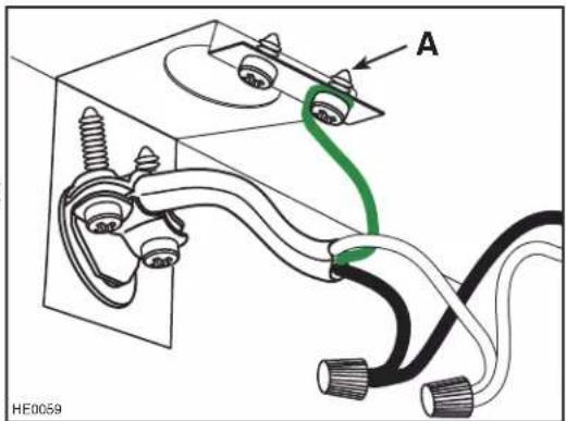
RIGHT SIDE MOUNTING SCREW LOCATIONS HD037217. CONNECT WIRING (ALL MODELS)
WARNING
Risk of electric shock. Electrical wiring must be done by qualified personnel in accordance with all applicable codes and standards. Before connecting wires, switch power off at service panel and lock service disconnecting means to prevent power from being switched on accidentally.
Insert the house wiring cable through the wire clamp previously installed in step 9. Tighten the wire clamp to secure the cable.
Connect cable using provided wire connectors.
Connect wires as follows: BLACK to BLACK, WHITE to WHITE and GREEN or BARE wire under ground screw. DO NOT FORGET TO CONNECT THE GROUND.
text_image
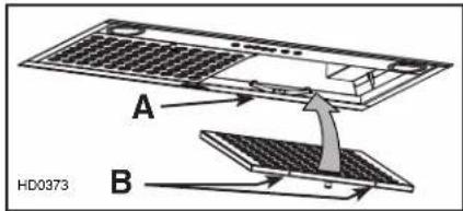
A HE005918. REINSTALL FRONT PANEL AND WIRING COVER
CAUTION
Take care not to pinch wiring when reinstalling the front panel and the wiring cover.
Carefully reassemble the front panel to the power pack by aligning the tabs with their corresponding slot. Using a Robertson or a Phillips no. 2 screwdriver, secure the front panel to the power pack using its both retaining screws (A) previously removed in step 8. Reassemble the wiring cover using its both retaining screws (B) previously removed in step 8. Plug the motor(s) (one or two, depending on model) to the front panel.
natural_image
Technical line drawing of a mechanical assembly with no visible text or symbols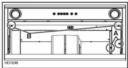
text_image
HD1098 A B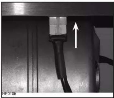
natural_image
Close-up of a mechanical component with a white arrow pointing upward, no visible text or symbols19. REINSTALL FILTERS
CAUTION
Remove protective plastic film covering filters before installing them.
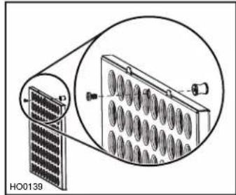
- Using a Phillips no. 2 screwdriver, assemble the knob to each filter. NOTE: The screw MUST BE on filter tabs side. See illustration at right.
natural_image
Diagram of a solar panel connected to a multi-layered array device, showing internal structure and mounting points (no text or symbols)- Rest rear filters edge on filter springs (A) in the power pack.
- Using knob, tilt up the filters into position. Make sure filter tabs (B) are securely engaged in power pack front edge after installation.
text_image
A B HD037320. LED LIGHTING
The lighting of this unit is produced by two LED modules (included).
WARNING
Do not touch lamps during or soon after operation. Burns may occur. Cannot be replaced by any other type of light bulb or LED module.
21. USE AND CARE
Filters
The filters should be cleaned frequently. Use a warm detergent solution. Wash more often if your cooking style generates more grease — like frying foods or wok cooking.
Remove filter by pushing it towards the back of power pack and rotating filter downward. Filters are dishwasher safe. Allow filters to dry completely before reinstalling them in the power pack.
Clean all-metal filters in the dishwasher using a non-phosphate detergent. Discoloration of the filters may occur if using phosphate detergent or as a result of local water conditions — but this will not affect filter performance. This discoloration is not covered by the warranty.
Power Pack Cleaning
Stainless steel cleaning:
Do:
- Regularly wash with clean cloth or rag soaked with warm water and mild soap or liquid dish detergent.
• Always clean in the direction of original polish lines. - Always rinse well with clear water (2 or 3 times) after cleaning. Wipe dry completely.
- You may also use a specialized household stainless steel cleaner.
Don't:
- Use any steel or stainless steel wool or any other scrapers to remove stubborn dirt.
- Use any harsh or abrasive cleansers.
- Allow dirt to accumulate.
- Let plaster dust or any other construction residues reach the power pack. During construction or renovation, cover the power pack to make sure no dust adheres to stainless steel surface.
Avoid when choosing a detergent:
- Any cleaners that contain bleach will attack stainless steel.
- Any products containing: chloride, fluoride, iodide, bromide will deteriorate surfaces rapidly.
- Any combustible products used for cleaning such as acetone, alcohol, ether, benzol, etc., are highly explosive and should never be used close to a range.
22. OPERATION
WARNING
When using a gas stove, always turn the power pack blower(s) on prior to begin cooking. In addition, the blower(s) must be at least in third speed if three burners or more are turned on simultaneously. Failure to do so may lead the surface of the power pack to become very hot.
Always turn your power pack on before you begin cooking to establish an air flow in the kitchen. Let the blower run for a few minutes to clear the air after you turn off the range. This will help keep the whole kitchen cleaner and brighter.
flowchart
graph LR
    A["①"] --> B["②"]
    B --> C["③"]
    C --> D["④"]
    D --> E["⑤"]
    style A fill:#f9f,stroke:#333
    style B fill:#f9f,stroke:#333
    style C fill:#f9f,stroke:#333
    style D fill:#f9f,stroke:#333
    style E fill:#f9f,stroke:#333
    note right of A: HC0023
    note right of B: B
    note right of C: C
    note right of D: D
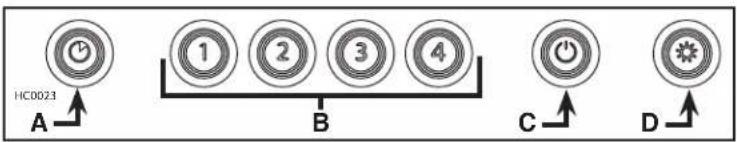
A. DELAY SWITCH:
When a blower speed is selected, press this switch to activate the delay function. The corresponding blower speed switch will flash to indicate this function is activated. The blower will continue to operate for 5 minutes and will stop automatically. To cancel the delay function, press the delay switch once again.
B. START/STOP/SPEED SELECTION SWITCHES:
Press the switch corresponding to the desired blower speed (from 1 for low speed to 4 for high speed). The chosen switch will light. To turn off the blower, press once more on the corresponding blower speed switch; the switch light will shut off. NOTE: When blower is off, pressing on blower speed 1 switch will cause the blower to start on high speed for a very short lapse of time, and then resume on speed 1.
C. MASTER OFF/FILTER MAINTENANCE/HEAT SENTRY™ (TRIPLE FUNCTION SWITCH):
i. To turn off the blower(s) and the light simultaneously, press this switch once.
ii. After 25 hours of operation, this switch will light to indicate the filters and the blower wheel(s) need to be cleaned in order to maintain efficient operation of the unit. The switch light will stay on until the function is reset by pressing this switch for 3 seconds.
iii. The light indicator is used for the Heat Sentry function as well.
HEAT SENTRY: The power pack is equipped with a protective device that activates when excessive heat is detected inside the power pack and when it is set on speed 4. This device takes control of the blower and deactivates speed 4 for a 10-minute period and sets it on speed 3. During the Heat Sentry activation, only speed 3 can be used; the Heat Sentry button (C) will flash while the speed 3 button will light. The power pack can also be turned OFF.
D. LIGHT SWITCH:
This switch allows two different lighting levels according to your needs. Press once for full intensity, twice for nightlight. To shut off the lights without turning off the blower, press once more.
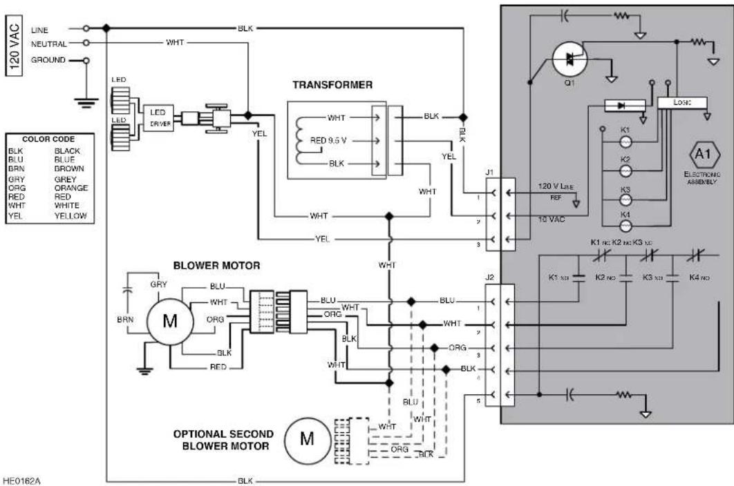
23. WIRING DIAGRAM
flowchart
graph TD
    A["120 VAC"] --> B["LINE"]
    A --> C["NEUTRAL"]
    A --> D["GROUND"]
    B --> E["LED"]
    C --> F["LED"]
    D --> G["Ground"]
    E --> H["LED DRIVER"]
    F --> I["YEL"]
    H --> J["TRANSFORMER"]
    I --> J
    J --> K["WHT"]
    J --> L["RED 9.5V"]
    J --> M["BLK"]
    J --> N["YEL"]
    K --> O["WHT"]
    L --> P["WHT"]
    M --> Q["WHT"]
    N --> R["YEL"]
    O --> S["J1"]
    P --> T["J2"]
    Q --> U["J3"]
    R --> V["J4"]
    S --> W["120 V Line REF"]
    T --> X["10 VAC"]
    U --> Y["Logic Gate"]
    V --> Z["A1 ELECTRONIC ASSEMBLY"]
    W --> AA["BLOWER MOTOR"]
    X --> AB["BLOWER MOTOR"]
    Y --> AC["BLOWER MOTOR"]
    Z --> AD["K1 SD"]
    Z --> AE["K2 SD"]
    Z --> AF["K3 SD"]
    Z --> AG["K4 SD"]
    AA --> AH["M"]
    AB --> AI["M"]
    AC --> AJ["M"]
    AD --> AK["OPTIONAL SECOND BLOWER MOTOR"]
    AE --> AL["OPTIONAL SECOND BLOWER MOTOR"]
    AF --> AM["OPTIONAL SECOND BLOWER MOTOR"]
    AG --> AN["OPTIONAL SECOND BLOWER MOTOR"]
24. SERVICE PARTS
CC65I28SB
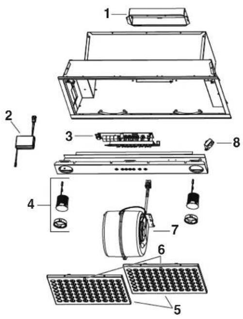
text_image
Exploded diagram of an electronic device with numbered components for identificationHL0447
CC67I28SB
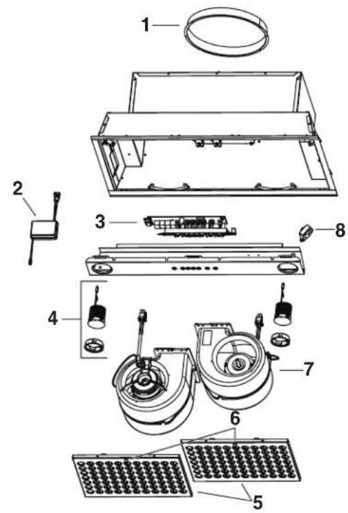
text_image
Exploded view diagram of an electronic device with numbered parts for identification| KEYNO. | PART NO. | DESCRIPTION | QTY. (POWER PACK MODEL) | |
| CC65I28SB CC67I28SB | ||||
| 1 | SV13296 A | DAPTER/DAMPER 3 14 " x 10" | 1 | - |
| SV08541 A | DAPTER 10" ROUND - 1 | |||
| 2 62248 LED D | RIVER AND CONNECTION HARNESS | 1 | 1 | |
| 3 SV21244 E | LECTRONIC CONTROL WITH CHROMED BUTTONS AND BLUE LEDs | 1 | 1 | |
| 4 62612 LED | MODULE (1) | 2 | 2 | |
| 5 SV18428 T | HIN BAFFLE FILTER | 2 | 2 | |
| 6 SV08967 F | ILTER KNOBS (INCLUDING SCREWS) (SET OF 2) | 1 | 1 | |
| 7 SV08582 I | NTERNAL BLOWER | 1 | 2 | |
| 8 SV09022 T | RANSFORMER | 1 | 1 | |
| * | SV05869 | BEST LOGO | 1 | 1 |
| * | SV23862 | INSTALLATION MANUAL | 1 | 1 |
| * | SV08545 | PARTS BAG: 2 WIRE CONNECTOR, 1 WIRE CLAMP,4 SCREWS NO. 8 x 3/8", 9 CHROMED PLATED SCREWS NO. 8-10 x 1/2",10 MECHANICAL SCREWS NO. 8-32 x 1/4" | 1 | 1 |
*Not shown
REPLACEMENT PARTS AND REPAIRS
In order to ensure your unit remains in good working condition, you must use Broan-NuTone genuine replacement parts only. Broan-NuTone genuine replacement parts are specially designed for each unit and are manufactured to comply with all the applicable certification standards and maintain a high standard of safety. Any third party replacement part used may cause serious damage and drastically reduce the performance level of your unit, which will result in premature failing. Broan-NuTone recommends to contact a certified service depot for all replacement parts and repairs.
FIVE-YEAR LIMITED WARRANTY FOR BEST® PRODUCTS
Warranty Period and Exclusions: Broan-NuTone, LLC (the "Company") warrants to the consumer purchaser of its product ("you") that the product (the "Product") will be free from material defects in the materials or its workmanship for a period of five (5) years from the date of original purchase (or such longer period as may be required by applicable law) or a period of two (2) years from the date of service for any labor provided on the Product.
The limited warranty period for any replacement parts provided by the Company and for any Products repaired or replaced under this limited warranty shall be the remainder of the original warranty period (or such longer period as may be required by applicable law).
THIS WARRANTY DOES NOT EXTEND TO FLUORESCENT LAMP STARTERS, TUBES AND BULBS, FUSES, FILTERS, DUCTS, ROOF CAPS, WALL CAPS AND OTHER ACCESSORIES FOR DUCTING. This warranty does not cover (a) normal maintenance and service, (b) normal wear and tear, (c) any Products or parts which have been subject to misuse, abuse, abnormal usage, negligence, accident, improper or insufficient maintenance, storage or repair (other than repair by the Company), (d) damage caused by faulty installation, or installation or use contrary to recommendations or instructions, (f) damage caused by exposure to salt air, (g) damage in transit, (h) natural wear of finish, (i) Products in commercial or nonresidential use, (j) damage caused by fire, flood or other act of God, or (k) Products with altered, defaced or removed serial numbers. This warranty covers only Products sold to consumers in North America. This warranty supersedes all prior warranties and, subject to applicable law, is not transferable from the original consumer purchaser.
No Other Warranties: This Limited Warranty contains the Company's sole obligation and your sole remedy for defective Products. The foregoing warranties are exclusive and in lieu of any other warranties and conditions, express or implied. TO THE MAXIMUM EXTENT PERMITTED BY APPLICABLE LAW, THE COMPANY DISCLAIMS AND EXCLUDES ALL OTHER EXPRESS WARRANTIES AND CONDITIONS, AND DISCLAIMS AND EXCLUDES ALL WARRANTIES AND CONDITIONS IMPLIED BY LAW, INCLUDING WITHOUT LIMITATION THOSE OF MERCHANTABILITY AND FITNESS FOR A PARTICULAR PURPOSE.
To the extent that applicable law prohibits the exclusion of implied warranties or conditions, the duration of any applicable implied warranty or condition is limited to the period specified for the express warranty above. Some jurisdictions (which may include the Province of Quebec or specific US states) do not allow limitations on how long an implied warranty lasts, so the above limitation may not apply to you. Any oral or written description of the Product is for the sole purpose of identifying it and shall not be construed as an express warranty.
Whenever possible, each provision of this Limited Warranty shall be interpreted in such manner as to be effective and valid under applicable law, but if any provision is held to be prohibited or invalid, such provision shall be ineffective only to the extent of such prohibition or invalidity, without invalidating the remainder of such provision or the other remaining provisions of the Limited Warranty.
Remedy: During the applicable limited warranty period, the Company will, at its option, provide replacement parts for, or repair or replace, without charge, any Product or part thereof, to the extent the Company finds it to be covered by and in breach of this limited warranty under normal use and service. The Company will ship the repaired or replaced Product or replacement parts to you at no charge. You are responsible for all costs for removal, reinstallation and shipping, insurance or other freight charges incurred in the shipment of the Product or part to the Company. If you must send the Product or part to the Company, as instructed by the Company, you must properly pack the Product or part—the Company is not responsible for damage in transit. The Company reserves the right to utilize reconditioned, refurbished, repaired or remanufactured Products or parts in the warranty repair or replacement process. Such Products and parts will be comparable in function and performance to an original Product or part and warranted for the remainder of the original warranty period (or such longer period as may be required by applicable law).
Company reserves the right, in its sole discretion, to refund the money actually paid by you for the Product. If the Product or component is no longer available, replacement may be made with a similar product of equal or greater value, at Company's sole discretion. This is your sole and exclusive remedy for breach of this limited warranty.
Exclusion of Damages: THE COMPANY'S OBLIGATION TO PROVIDE REPLACEMENT PARTS, OR REPAIR OR REPLACE, AT THE COMPANY'S OPTION, SHALL BE YOUR SOLE AND EXCLUSIVE REMEDY UNDER THIS LIMITED WARRANTY AND THE COMPANY'S SOLE AND EXCLUSIVE OBLIGATION. THE COMPANY SHALL NOT BE LIABLE FOR INCIDENTAL, INDIRECT, CONSEQUENTIAL OR SPECIAL DAMAGES ARISING OUT OF OR IN CONNECTION WITH THE PRODUCT, ITS USE OR PERFORMANCE.
Some jurisdictions do not allow the exclusion or limitation of incidental or consequential damages, so the above limitation or exclusion may not apply to you. This warranty gives you specific legal rights, and you may also have other rights, which vary from jurisdiction to jurisdiction. The disclaimers, exclusions, and limitations of liability under this warranty will not apply to the extent prohibited by applicable law.
This warranty covers only replacement or repair of defective Products or parts thereof at the Company's main facility and does not include the cost of field service travel and living expenses.
Any assistance the Company provides to or procures for you outside the terms, limitations or exclusions of this limited warranty will not constitute a waiver of such terms, limitations or exclusions, nor will such assistance extend or revive the warranty. The Company will not reimburse you for any expenses incurred by you in repairing or replacing any defective Product, except for those incurred with the Company's prior written permission.
How to Obtain Warranty Service: To qualify for warranty service, you must (a) notify the Company at the address or telephone number stated below within seven (7) days of discovering the covered defect, (b) give the model number and part identification and (c) describe the nature of any defect in the Product or part. At the time of requesting warranty service, you must present evidence of the original purchase date. If you cannot provide a copy of the original written limited warranty, then the terms of the Company's most current written limited warranty for your particular product will control.
PRODUCT SPECIFICATIONS
All illustrations and specifications in this catalog are based on the latest product information available at time of production. Broan-NuTone, LLC and BEST® reserves the right to make changes at any time, without notice, in prices, colors, materials, equipment, specifications and models, place of manufacture and to discontinue models or equipment.
Best
Broan-NuTone, LLC- 926 W. State Street, Hartford, WI 53207 1-800-637-1453
Best®, 550 Lemire Blvd., Drummondville, QC, Canada (1-866-737-7770) www.bestrangehoods.com
best®
natural_image
Technical line drawing of a cabinet or enclosure with circular components and ventilation grilles (no text or symbols)SÉRIE CC6
⚠️CONÇUE UNIQUEMENT POUR LA CUISSON DOMESTIQUE △
LIRE ET CONSERVER CES DIRECTIVES
INSTALLATEUR : LAISSER CE GUIDE AU PROPRIÉTAIRE. PROPRIÉTAIRE : DIRECTIVES D'UTILISATION ET D'ENTRETIEN EN PAGES 12 ET 13.
BEST; Hartford, Wisconsin www.BestRangeHoods.com 800 558-1711 BEST; Drummondville, QC, Canada www.BestRangeHoods.ca 866 737-7770

AVERTISSEMENT
AFIN DE RÉDUIRE LES RISQUES D'INCENDIE, D'ÉLECTROCUTION OU DE BLESSURES CORPORELLES, SUIVEZ LES DIRECTIVES SUIVANTES :
natural_image
Technical line drawing of a mechanical device with an open lid and grid array (no text or symbols)7. DÉBRANCHER LE(S) VENTILATEUR(S)
natural_image
Close-up of a mechanical component with a black cable and arrow indicating a downward motion (no text or symbols visible)8. RETIRER LE COUVERCLE DU COMPARTIMENT ÉLECTRIQUE ET LE PANNEAU AVANT
text_image
C D HR003010. RETIRER L'OUVERTURE PRÉAMORCÉE (VENTILATEUR SIMPLE SEULEMENT)
text_image
① ② HR003711. INSTALLER L'ADAPTATEUR/VOLET (VENTILATEUR SIMPLE SEULEMENT)
INSTALLATION À ÉVACUATION VERTICALE
natural_image
Technical line drawings of two mechanical components with no visible text or symbolsINSTALLATION À ÉVACUATION HORIZONTALE
text_image
EMPLACEMENT DES VIS HJ0035natural_image
Technical line drawing of a mechanical assembly with no visible text or symbols15. INSTALLER L'ADAPTATEUR/VOLET À L'ARRIÈRE DE LA HOTTE ENCASTRABLE (VENTILATEUR SIMPLE, ÉVACUATION HORIZONTALE SEULEMENT)
natural_image
Technical line drawing of a mechanical assembly with no visible text or symbols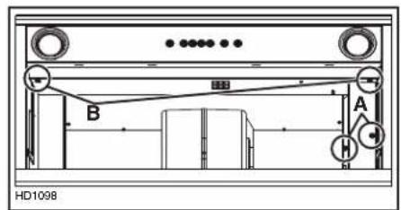
text_image
B A H HD1098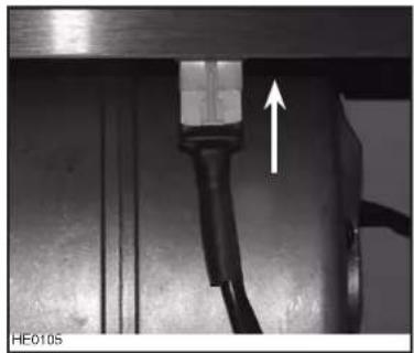
natural_image
Close-up of a mechanical component with a white arrow pointing upward, no visible text or symbols19. REMETTRE LES FILTRES EN PLACE
ATTENTION
natural_image
Technical diagram of a solar panel mounted on a cylindrical device with a circular housing (no text or symbols visible)text_image
Exploded diagram of an electronic device with numbered components for identificationHL0447
CC67I28SB

text_image
Exploded view diagram of a device with numbered parts for identification| N° DERÉF. | N° DE PIÈCE D | DESCRIPTION | QTÉ (MODÈLE DE HOTTE ENCASTRABLE) | |
| CC65I28SB CC67I28SB | ||||
| 1 | SV13296 A | DAPTATEUR/VOLET 3 14 PO X 10 PO | 1 | - |
| SV08541 A | DAPTATEUR 10 PO ROND - 1 | |||
| 2 62248 M | ODULE D'ALIMENTATION DEL ET FAISCEAU DE CONNECTION | 1 | 1 | |
| 3 SV21244 C | OMMANDE ÉLECTRONIQUE AVEC BOUTONS CHROMÉS ET DEL BLEUES | 1 | 1 | |
| 4 62612 M | ODULE À DEL (1) 2 2 | |||
| 5 SV18428 F | ILTRES À CHICANE MINCES | 2 | 2 | |
| 6 SV08967 B | OUTONS DE FILTRE (VIS INCLUDES) (JEU DE 2) | 1 | 1 | |
| 7 SV08582 V | ENTILATEUR | 1 | 2 | |
| 8 SV09022 T | RANSFORMATEUR | 1 | 1 | |
| * | SV05869 L | OGO BEST | 1 | 1 |
| * | SV23862 G | UIDE D'INSTALLATION | 1 | 1 |
| * | SV08545 | SAC DE PIÈCES: 2 CAPUCHONS DE CONNEXION, 4 VIS N° 8 x 3/8 PO,9 VIS PLAQUÉES CHROME N° 8-10 x 1/2 PO, 1 SERRE-FILS,10 VIS À MÉTAUX N° 8-32 x 1/4 PO | 1 | 1 |
*Non illustré
PIÈCES DE REMPLACEMENT ET SERVICE
SPÉCIFICATIONS DU PRODUIT
Broan-NuTone LLC : 926 W. State Street, Hartford (WI) 53207 1 800 637-1453
Best ^™ , 550, boul. Lemire, Drummondville (Québec), Canada (1 866 737-7770) fr.bestrangehoods.ca
best®
natural_image
Technical line drawing of a cabinet or enclosure with circular components and ventilation grilles (no text or symbols)SERIE CC6
⚠️! DESTINADA ÚNICAMENTE PARA COCINAS DOMÉSTICAS △
LEA Y GUARDE ESTAS INSTRUCCIONES
INSTALADOR: DEJE ESTE MANUAL AL PROPIETARIO.
BEST; Drummondville, QC, Canada www.BestRangeHoods.ca 866-737-7770
PARA REDUCIR EL RIESGO DE INCENDIO, CHOQUE ELÉCTRICO O HERIDAS CORPORALES, SIGA LAS INDICACIONES SIGUIENTES:
text_image
10-1/2" 3/4" 9-3/4" 10-1/8" 7/8" 3-1/4" 1-11/16" 13-5/16" 2-3/4" 9-7/8" 26-5/8" 13-1/4" 14-3/4" 28-1/8" 1-1/16" HK02024CC67I28SB
CAMPANA EXTRACTORA EMPOTRABLE PARA DOS VENTILADORES
text_image
10-1/2" 10" 5 1/4" 7/8" 13-15/16" 2-3/4" 9-7/8" 1-1/16" 2-15/16" 26-5/8" 28-1/8" 13-1/4" 14-3/4" 16207A4. INSTALE EL REVESTIMIENTO DE LA CAMPANA A MEDIDA (OPCIONAL)
natural_image
Technical line drawing of a portable electronic device with ventilation grilles and an upward arrow indicating airflow (no text or symbols)7. DESENCHUFE EL O LOS VENTILADORES
natural_image
Close-up of a mechanical component with a black cable and arrow indicating a downward motion (no text or symbols visible)text_image
C D HR003010. RETIRE LA APERTURA TROQUELADA (SÓLO EN EL MODELO CON UN SOLO VENTILADOR)
text_image
① ② HR003711. INSTALE EL ADAPTADOR/COMPUERTA (SÓLO EN EL MODELO CON UN SOLO VENTILADOR)
natural_image
Technical line drawings of two mechanical components with mounting bases and a coiled spring (no text or symbols)natural_image
Technical line drawing of a mechanical assembly with no visible text or symbols15. INSTALE EL ADAPTADOR/COMPUERTA EN LA PARTE POSTERIOR DE LA CAMPANA EXTRACTORA EMPOTRABLE (MODELO CON UN SOLO VENTILADOR, DESCARGA HORIZONTAL SOLAMENTE
natural_image
Technical line drawing of a mechanical assembly with no visible text or symbols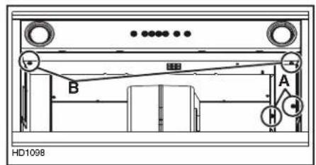
text_image
HD1098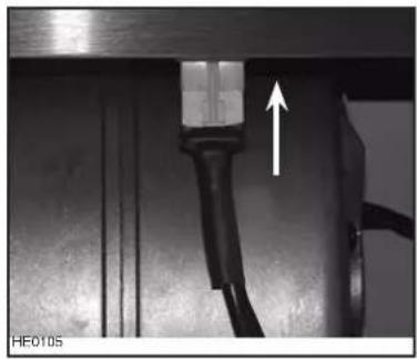
natural_image
Close-up of a mechanical component with a white arrow pointing to a connector or cable (no text or symbols visible)19. VUELVA A INSTALAR LOS FILTROS
PRECAUCIÓN
natural_image
Technical diagram of a solar panel mounted on a cylindrical device with a circular housing (no text or symbols visible)text_image
Exploded diagram of an electronic device with numbered components for identificationHL0447
CC67I28SB

text_image
Exploded view diagram of an electronic device with numbered parts for identification| N.° | N.° DE PIEZA D | DESCRIPCIÓN | CANT. (MODELO DE CAMPANA EXTRACTORA EMPOTRABLE) | |
| CC65I28SB CC67I28SB | ||||
| 1 | SV13296 A | DAPTATDOR/COMPUERTA DE 3 14 " x 10" | 1 | - |
| SV08541 A | DAPTADOR REDONDO DE 10" | - | 1 | |
| 2 62248 M | ODULO DE ALIMENTACIÓN LED Y MAZO DE CABLES DE CONEXIÓN | 1 | 1 | |
| 3 SV21244 C | ONTROL ELECTRÓNICO CON BOTONES CROMADOS Y LEDS AZULES | 1 | 1 | |
| 4 62612 M | ÓDULO LED (1) | 2 | 2 | |
| 5 SV18428 F | ILTRO FINO | 2 | 2 | |
| 6 SV08967 P | OMOS DE LOS FILTROS (INCLUIDOS LOS TORNILLOS) (CANT.: 2) | 1 | 1 | |
| 7 SV08582 V | ENTILADOR INTERNO | 1 | 2 | |
| 8 SV09022 T | RANSFORMADOR | 1 | 1 | |
| * | SV05869 L | OGO BEST | 1 | 1 |
| * | SV23862 M | ANUAL DE INSTALACIÓN | 1 | 1 |
| * | SV08545 | BOLSA DE PIEZAS: 2 CONECTORES DE HILOS, 4 TORNILLOS N,° 8 x 3/8", 9 TORNILLOS CROMADOS N.° 8-10 x 1/2", 1 ABRAZADERA DE HILOS, 10 TORNILLOS MECÁNICOS N.° 8-32 x 1/4" | 1 | 1 |
* No SE MUESTRA
Broan-NuTone, LLC: 926 W. State Street, Hartford, WI 53207 1 800 637-1453
Best®, 550, boul. Lemire, Drummondville (Québec), Canada (1 866 737-7770) www.bestrangehoods.com