GIEH 634481 P - Cooker GRUNDIG - Free user manual and instructions
Find the device manual for free GIEH 634481 P GRUNDIG in PDF.

| Brand | Grundig |
| Model | GIEH 634481 P |
| Product type | Cooker with integrated hood (cooking hob + extractor hood) |
| Installation type | Built-in (recessed into a cabinet) |
| Electrical supply | 230 V single phase or 400 V three-phase, 50 Hz |
| Total power | Approximately 7.4 kW (refer to rating plate) |
| Number of cooking zones | 4 (estimate) |
| Cooking type | Ceramic glass electric hobs |
| Integrated hood | Yes, with recirculation and external extraction modes |
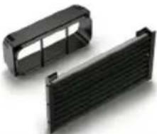
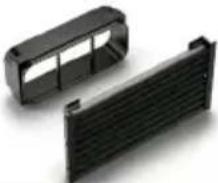
| Filters | Washable metal filter + activated charcoal filter |
| Hood capacity | Not specified in the manual extract |
| Noise level | Not specified |
| Weight | Approximately 35 kg (estimate) |
| Energy class | Not specified |
| Safety | Instructions: installation by a professional, disconnect before maintenance, do not touch hot surfaces |
| Cleaning | Metal filter dishwasher-safe; replace charcoal filter periodically (6-12 months) |
| Installation | Must be carried out by a qualified professional |
| Warranty | Subject to compliant installation |
| Included accessories | Metal filter, liquid collection chamber, worktop plastic (depending on type A) |
| Available spare parts | Filters, air guiding parts (Naber) |
Frequently Asked Questions - GIEH 634481 P GRUNDIG
User questions about GIEH 634481 P GRUNDIG
0 question about this device. Answer the ones you know or ask your own.
Ask a new question about this device
Download the instructions for your Cooker in PDF format for free! Find your manual GIEH 634481 P - GRUNDIG and take your electronic device back in hand. On this page are published all the documents necessary for the use of your device. GIEH 634481 P by GRUNDIG.
USER MANUAL GIEH 634481 P GRUNDIG
natural_image
Icon of a crossed wrench and screwdriver (no text or symbols)TR / EN / DE / FR / DA / FI / IT / NL / NO / PL / SV / BS / ES / ET / HR / IN / LT / LV / MK / PT / RO / RU / SK / SL / SQ / SB / TH / ZH
A2
| Y | Z | |
| 60 cm | 604 | 560 |
| 80 cm | 824 | 740 |
A3
natural_image
Technical line drawing of a device assembly showing a component being processed into a housing (no text or symbols present)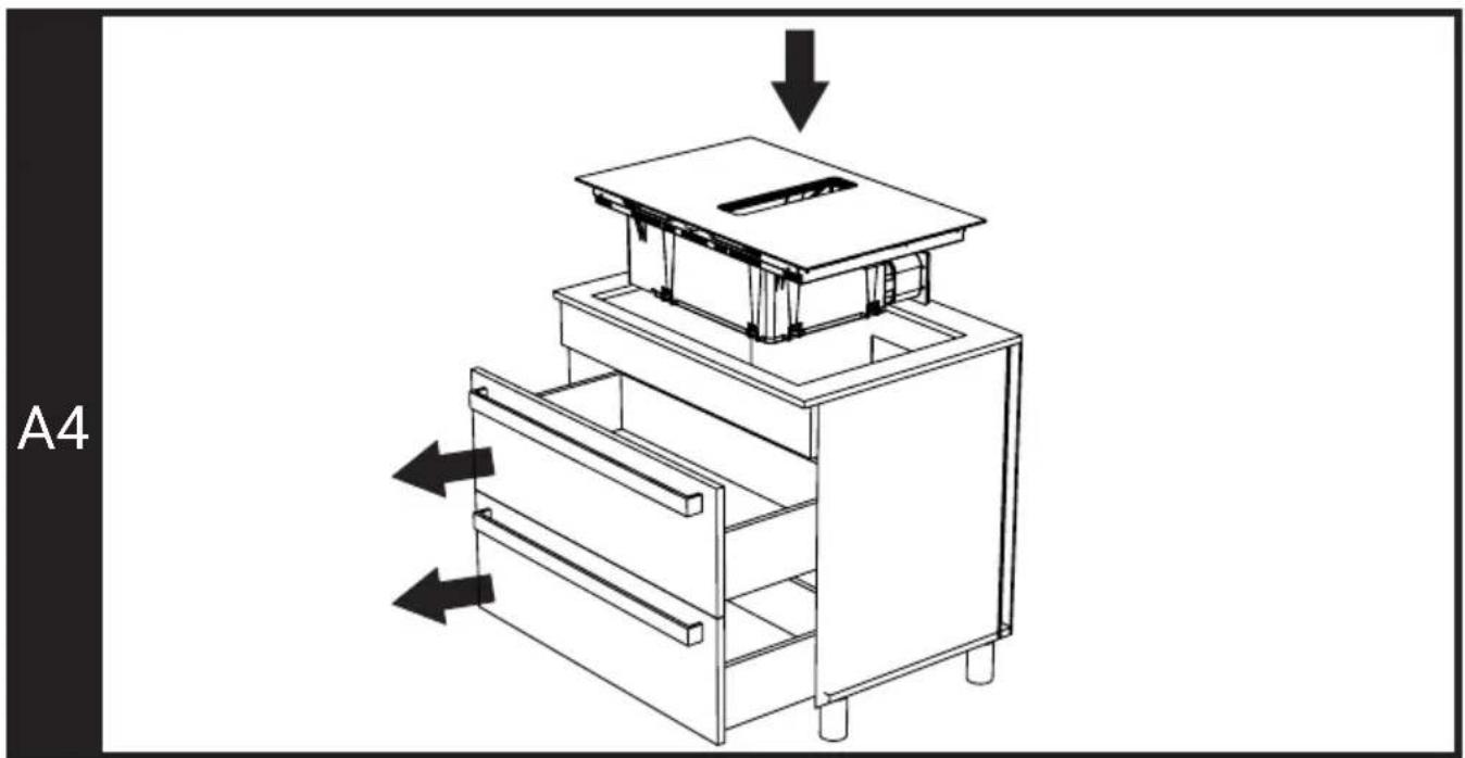
natural_image
Line drawing of a multi-tiered drawer cabinet with arrows indicating flow direction (no text or symbols)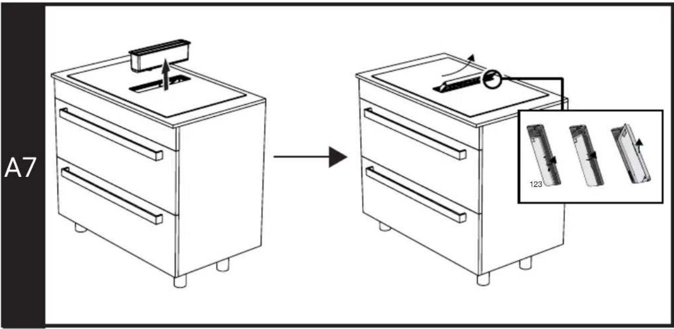
B2
| Y | Z | |
| 60 cm | 604 | 560 |
| 80 cm | 824 | 740 |
B3
natural_image
Technical line drawing of two mechanical assembly components with no visible text or symbolsB4
natural_image
Diagram of a mechanical device with internal components and directional arrows indicating motion (no text or symbols)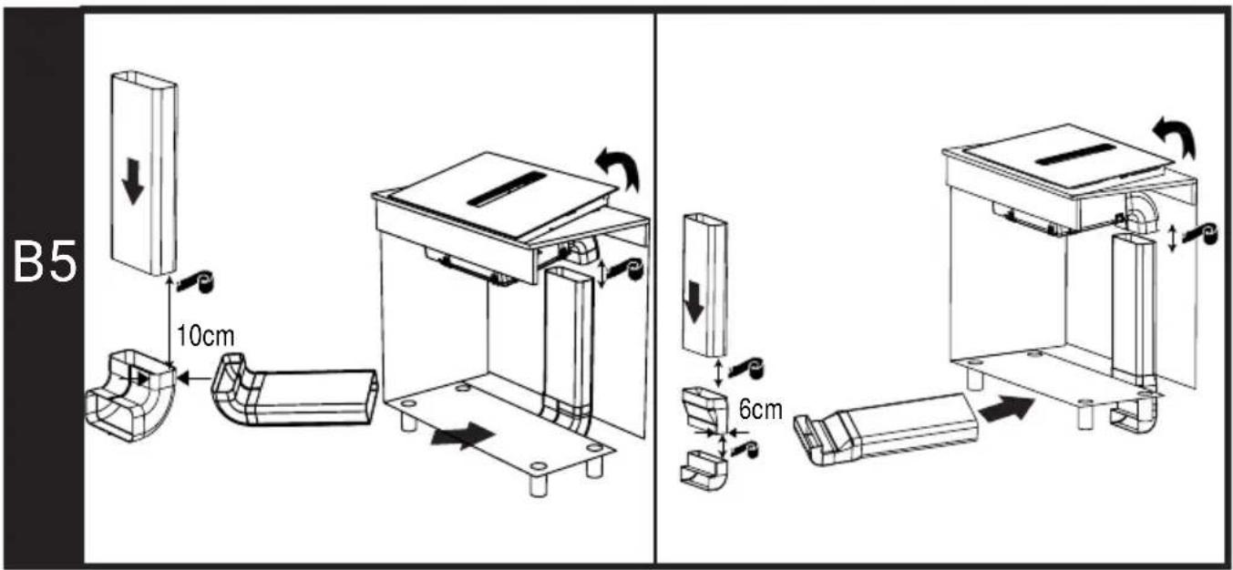
natural_image
Technical line drawing of a mechanical device with a downward arrow indicating a component (no text or symbols present)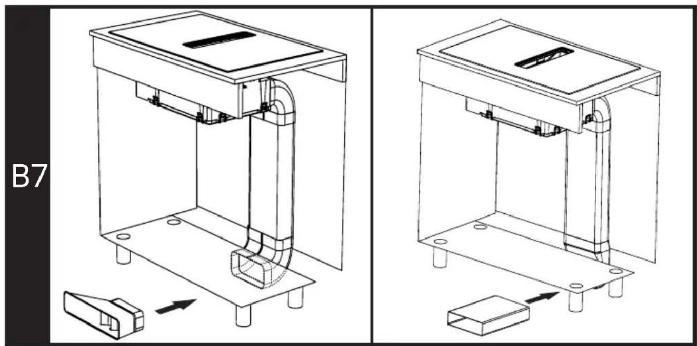
natural_image
Technical line drawings of a mechanical device with base and housing components, showing assembly steps (no text or symbols)B8
natural_image
Line drawing of a multi-compartment drawer cabinet with arrows indicating flow direction (no text or symbols)B9
B10
natural_image
Line drawing of a two-step appliance assembly showing front and side views (no text or symbols)B11
natural_image
Line drawing of a three-drawer drawer with an inset showing two rectangular objects labeled 123 (no text or symbols on the main diagram)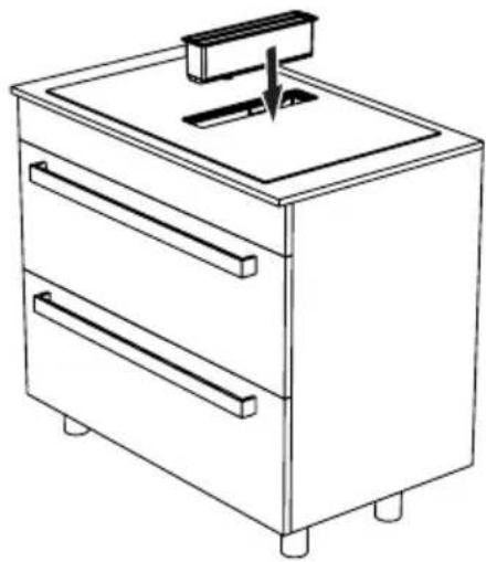
natural_image
Line drawing of a two-door appliance with a handle and top panel (no text or symbols)B12
natural_image
Four white plastic electronic components with no visible text or symbols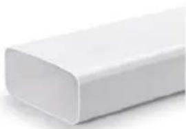
natural_image
White rectangular object with rounded edges, possibly a plastic or paper strip (no text or symbols visible)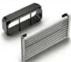
natural_image
Two electronic components: a black rectangular housing and a metallic heat sink with ribbed side (no text or symbols visible)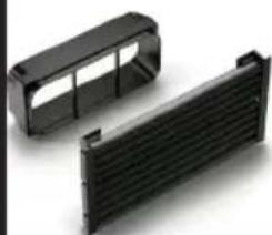
natural_image
Two black plastic heat exchanger housing components (no text or symbols visible)4048123
4043001*
8038014*
8038015*
| B13 | Y | |
 | 4048135 | |
 | 4028076* (100 cm) | |
 | 4028080* (50 cm) |
C2
| Y | Z | |
| 60 cm | 604 | 560 |
| 80 cm | 824 | 740 |
C3
natural_image
Technical line drawing of a mechanical assembly with a central component and directional arrow (no text or symbols)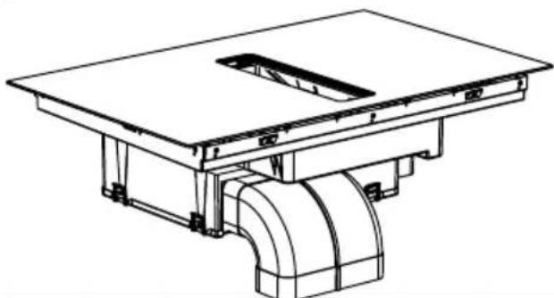
natural_image
Technical line drawing of a mechanical assembly with a rectangular base and curved pipe fitting (no text or symbols)C4
natural_image
Technical line drawing of a mechanical device with internal components and directional arrows indicating motion (no text or symbols)C5
natural_image
Technical diagram showing a device with a downward arrow and a rotating button, connected to a mechanical assembly (no text or symbols present)C6
natural_image
Technical line drawing of a mechanical device with internal components and directional arrows (no text or symbols)C7
natural_image
Technical line drawing of an electrical enclosure with internal components and directional arrows (no text or symbols)C8
natural_image
Technical line drawing of a mechanical device with internal components and directional arrows indicating motion (no text or symbols)| C9 | Y | |
 | 4043007 | |
 | 4022039 | |
 | 4022040 | |
 | 4022029 | |
 | 4022038 | |
 | 4022012 | |
 | 4043001 | |
 | 4043005 | |
 | 4043003 | |
 | 4043002 | |
 | 4043004 | |
 | 4043006 | |
 | 4043042 | |
 | 4043008 | |
 | 4021002 | |
 | 4021003 | |
 | 4021004 | |
 | 4021044 | |
 | 4043079 | |
 | 4052017 | |
 | 4052102 |
E
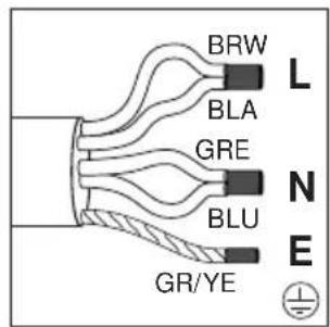
1 N AC 220-240 V
2 N AC 380-415 V
2 N AC 380-415 V
3 N AC 380-415 V
- (BRW/BLÄ) Kahverengi/Siyah = L (Faz)
- (BLU/GRE) Mavi/Gri = N (Nötr)
-(BRW) Kahverengi = L1 (Faz)
- (BLA) Siyah = L2 (Faz)
- (BLU/GRE) Mavi/Gri = N (Nötr)
- (BRW) Kahverengi = L1 (Faz)
- (BLA) Siyah = L2 (Faz)
- (BLU) Mavi = N (Nötr)
- (GR/YE) Yeşil/sarı kablo = (E) ⏚ (Topraklama)
-(BRW) Kahverengi = L1 (Faz)
- (BLA) Siyah = L2 (Faz)
- (GRE) Gri = L3 (Faz)
- (BLU) Mavi = N (Nötr)
- (GR/YE) Yeşil/sarı kablo = (E) ⏚ (Topraklama)
EN- Safety Instructions
- The appliance shall be installed by a qualified person in accordance with the regulations in force to keep the warranty applicable. The manufacturer shall not be held responsible for damages arising from procedures carried out by unauthorized persons which will also void the warranty.
- It is customer's responsibility to prepare the location the appliance shall be placed on and to have the electrical installation prepared. Before calling Authorized Service, make sure the electrical infrastructure is suitable. If it is not, call a qualified electrician and fitter to have the required arrangements made.
- The rules in local electrical installation standards shall be followed during product installation.
- Remove all packaging materials and documents inside the appliance and check for any damage on the appliance before the installation. Do not have it installed if the appliance is damaged.
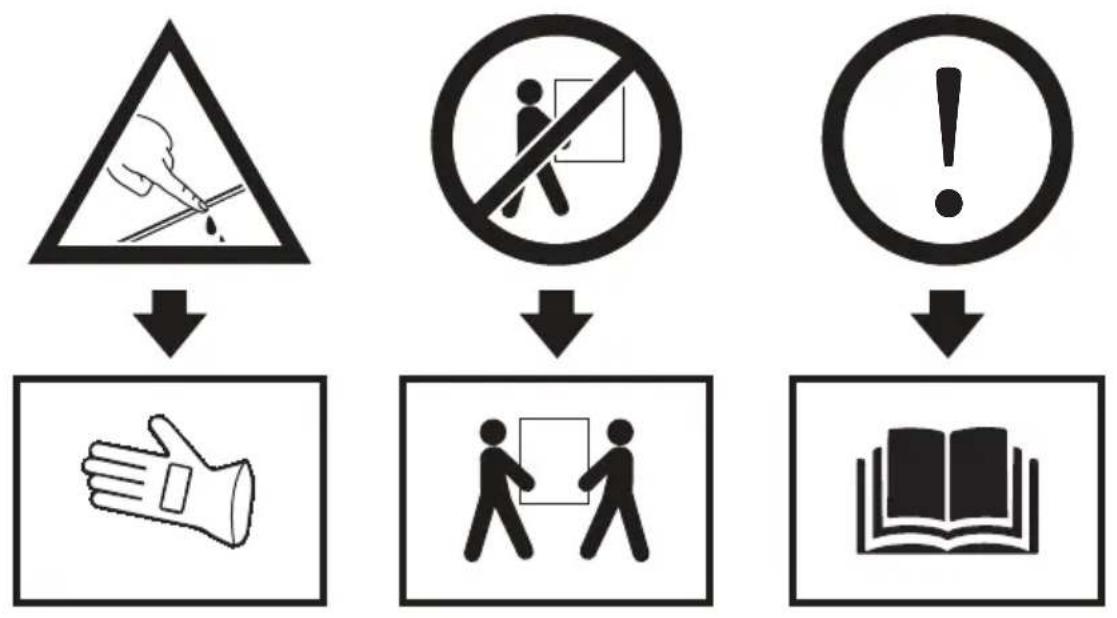
- The product is heavy, carry the product with at least two people.
- Make sure that the user cannot reach the electrical connections after the installation.
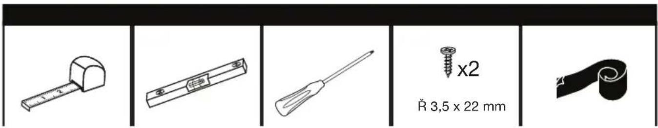
- Failing to install the screws and securing equipments in accordance with the guide may cause electrical danger.
- Parts that you may be in touching distance during the installation may have sharp edges and may cause cut injuries. Therefore always wear protective gloves during transport and installation.
- Disconnect electrical connections in the area of installation before starting the installation.
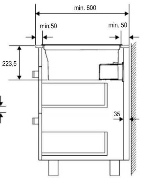
- Surfaces of the furniture that the appliance shall be installed shall be heat resistant (100 °C minimum).
- Make sure that the furniture is in straight, horizontal position and that it is fixed before the installation of the appliance.
- Do not install heat insulation strips to the furniture that the appliance shall be installed.
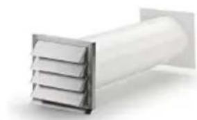
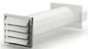
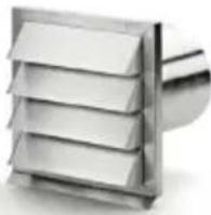
- The air to be expelled from the product should not be fed into a chimney used by other appliances burning gas or other fuels. (not applicable for appliances that discharge air back into the room).
•Legislation regarding the evacuation of air must be complied with.
- Poisoning Danger! While the appliance is operating, air is drawn from the whole house. If adequate ventilation is not provided, air flow occurs and the waste and toxic gases released as a result of combustion in the house are reabsorbed. Do not operate the product together with products that provide air circulation and may emit toxic gas (wood, gas, oil and coal stoves, boilers, water heaters, etc.).
- Have the adequacy of your building's ventilation and chimney system checked by authorized persons.
- If there is another appliance operating with energy other than electrical energy in the same environment with ventilation, the negative pressure in the room should be at most 0.04 mbar so that the exhaust of the other appliance is not drawn back into the room by the ventilation.
- Dimensions given in installation diagrams are in mm.
•Legislation regarding the evacuation of air must be complied with.
- Oil sludges may form on metal oil filters. For that reason, there should not be any flame near the product. In addition, installation of the product near a heating equipment using solid fuel is only permitted if there is a non-removable closed cover to prevent sparks.
- Our company shall not be responsible for problems that arise for not observing any of the warnings above.
•The product manufacturer does not accept any responsibility for the defects caused by the ventilation pipes used in the installation.
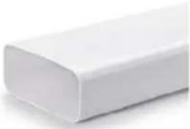
- The air outlet pipe to be used should be as short as possible, straight and should have a large diameter.
- Long air outlet pipes, multiple pipe bends or small pipe diameters reduce ventilation performance and increase fan noise.
- The air outlet pipe must be made of non-combustible material.
- The air outlet pipe should be installed with an inclination of 1 degree to prevent the return of condensation.
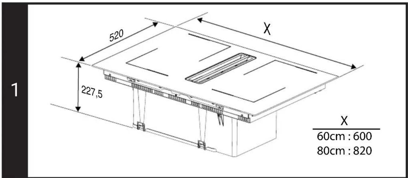
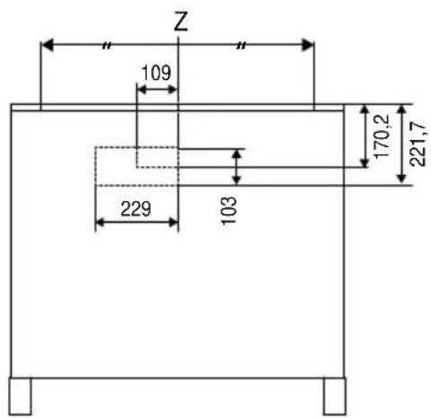
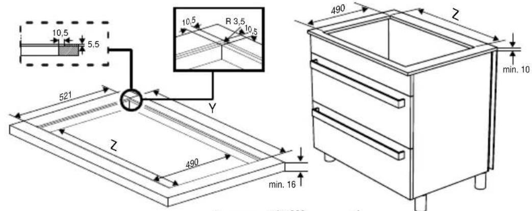
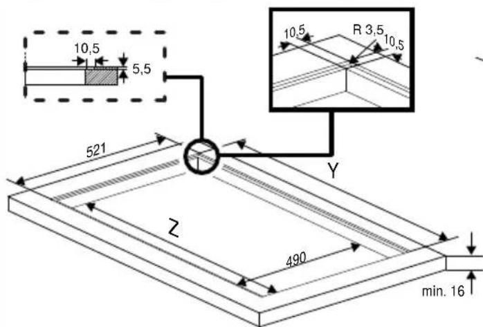
Product dimensions (Figure 1)
Pay attention to the product dimensions. Consider its suitability with your furniture. Your product is suitable for 3 different types of installation according to the suitability of your furniture. A, B and C type installations are described respectively.
A : Installation without internal circulation shaft
B : Installation with internal circulation shaft
C : Installation with external circulation
A type installation (Installation without internal circulation shaft)
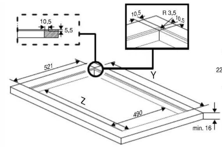
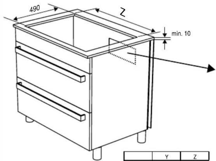
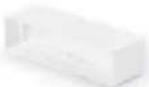
Preparation of the furniture on which installation will be made: (Figure A2)
Prepare your furniture according to the dimensions presented in Figure A2. Cut dimensions for flush-fit installation are also indicated in Figure A2.
Steps for A type installation
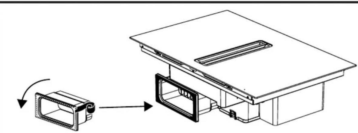
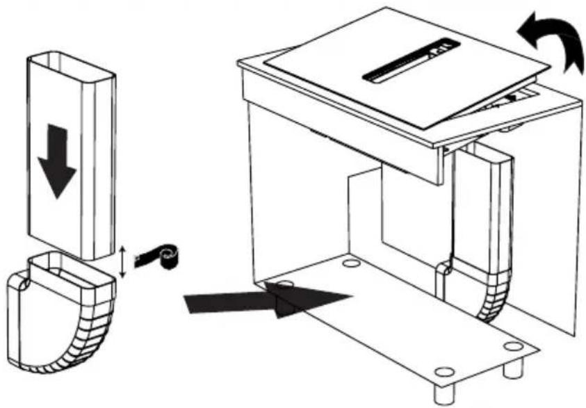
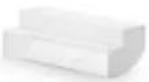
- Remove the tape on the countertop plastic described in Figure A3, and place it in its slot on the back of the hob as shown in the figure.
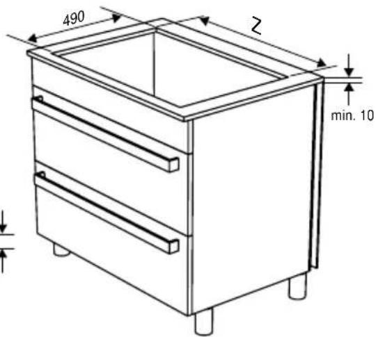
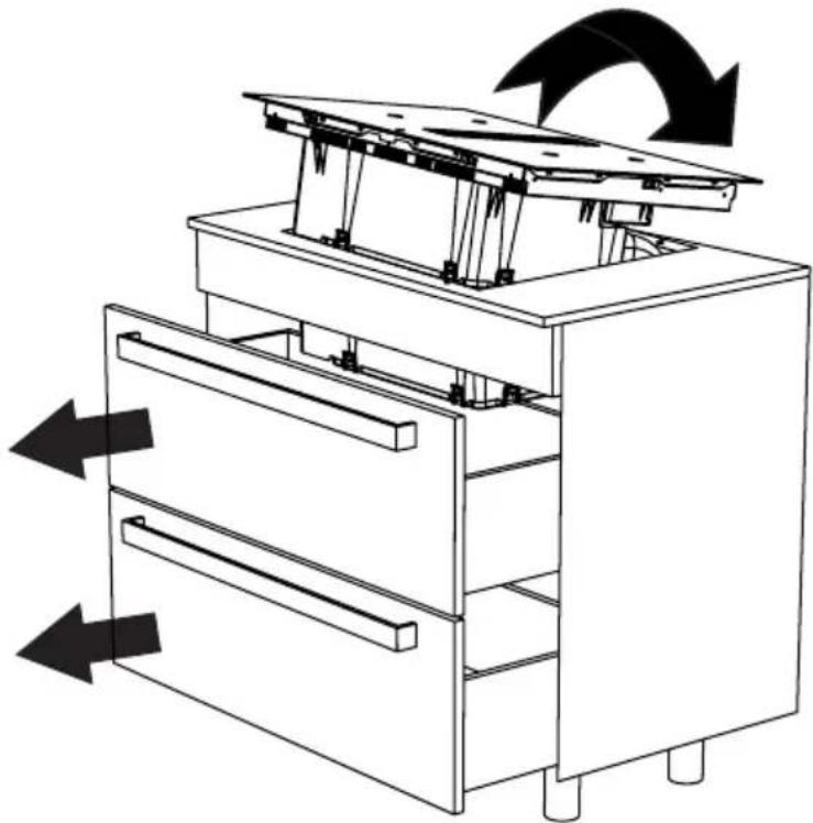
- Completely remove the drawers of your furniture and place your stove in its place on your furniture. (Figure A4)
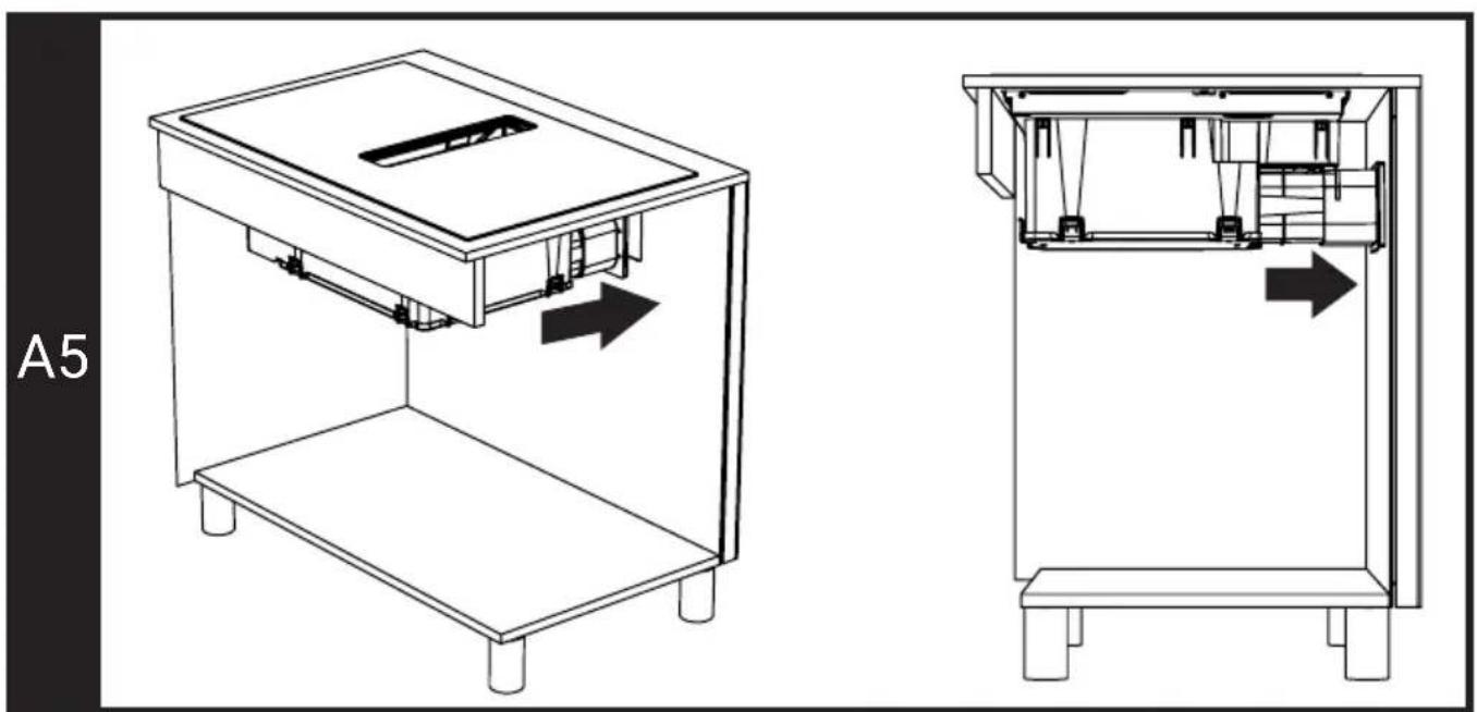
- Stick the countertop plastic on the wall by pulling it towards the wall through the gap you have opened in your furniture. (Figure A5)
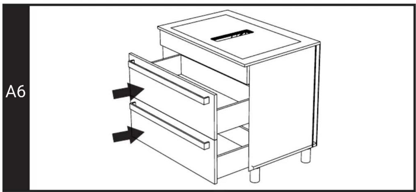
- Put your drawers back in place. (Figure A6)
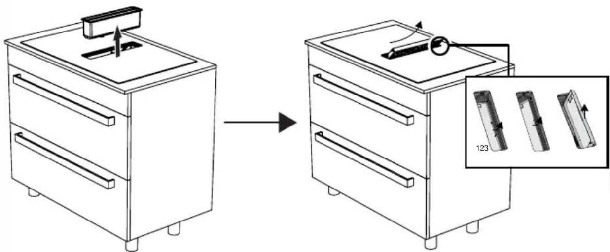
- Remove the metal oil filter by pulling it upwards. (Figure A7)
- Remove the liquid collection chamber as shown in the figure A7.
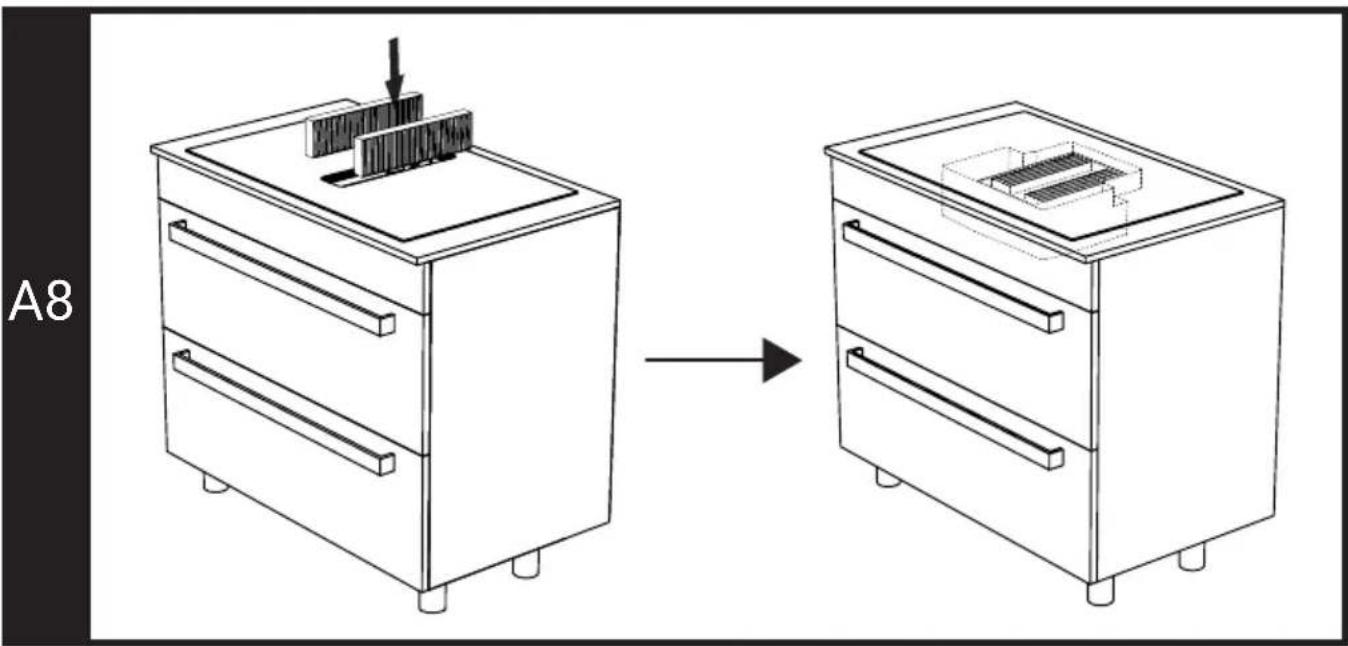
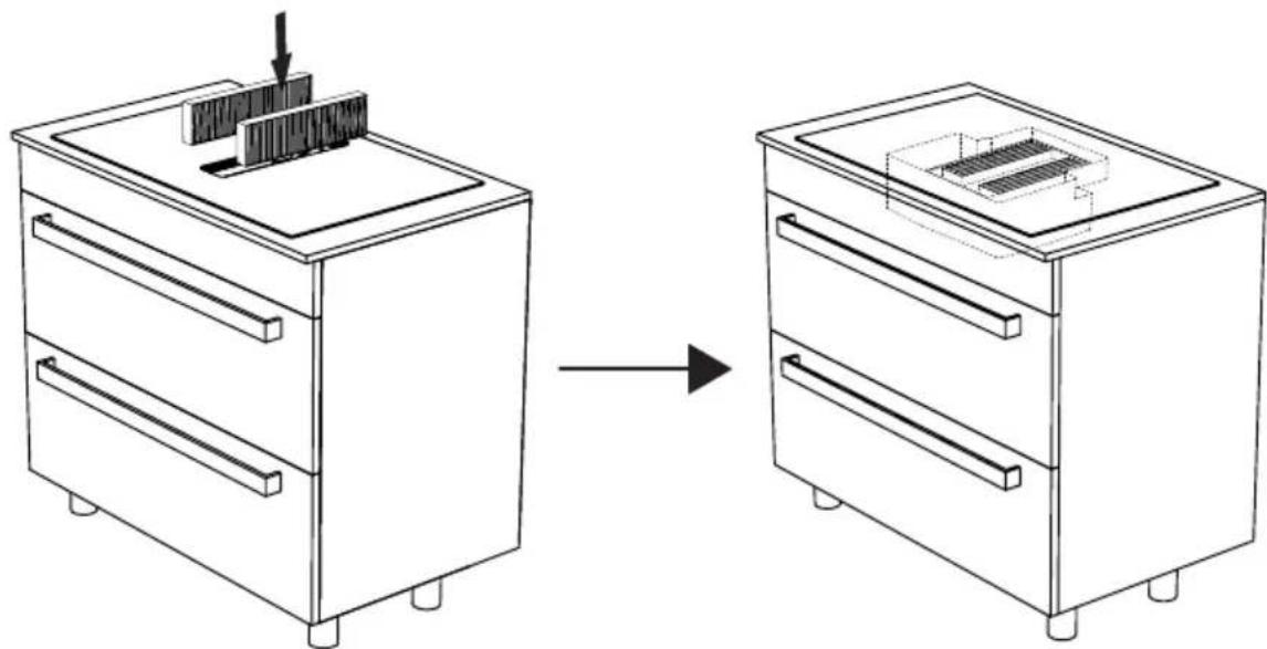
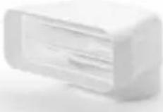
- Place two units of active carbon filters to right and left as shown in figure A8.
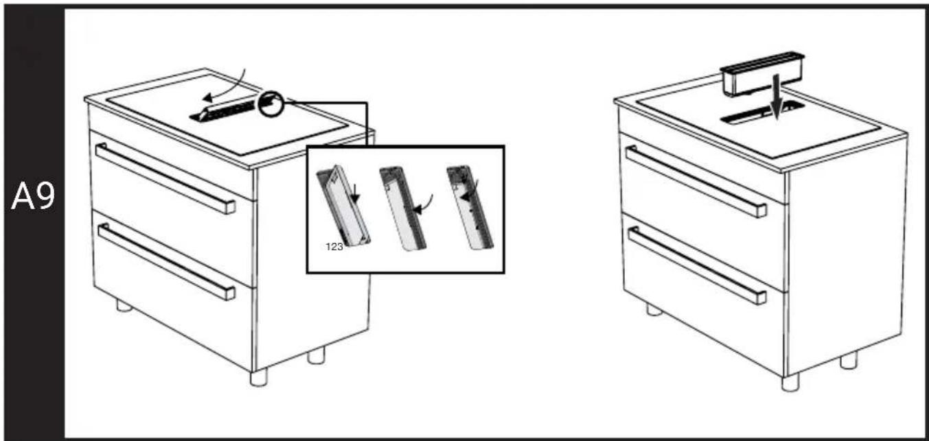
- Place back the liquid collection chamber as shown in the figure A9. Complete the installation by placing back the metal oil filter.
B type installation (Installation with internal circulation shaft)
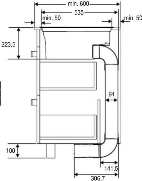
Preparation of the furniture on which installation will be made: (Figure B2)
Prepare your furniture according to the dimensions presented in Figure B2. Cut dimensions for flush-fit installation are also indicated in Figure B2. You need to obtain the plastic parts of the air guide described in this installation from the authorized service or authorized dealers. These parts are not supplied with the product.
Steps for B type installation
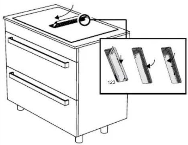
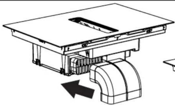
- Place the ventilation corner plastic described in Figure B3 in its slot on the back of the hob as shown in the figure.
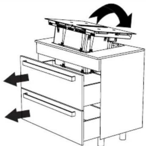
- Completely remove the drawers of your furniture and place your stove by tilting it
into its place on your furniture. (Figure A4)
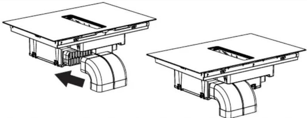
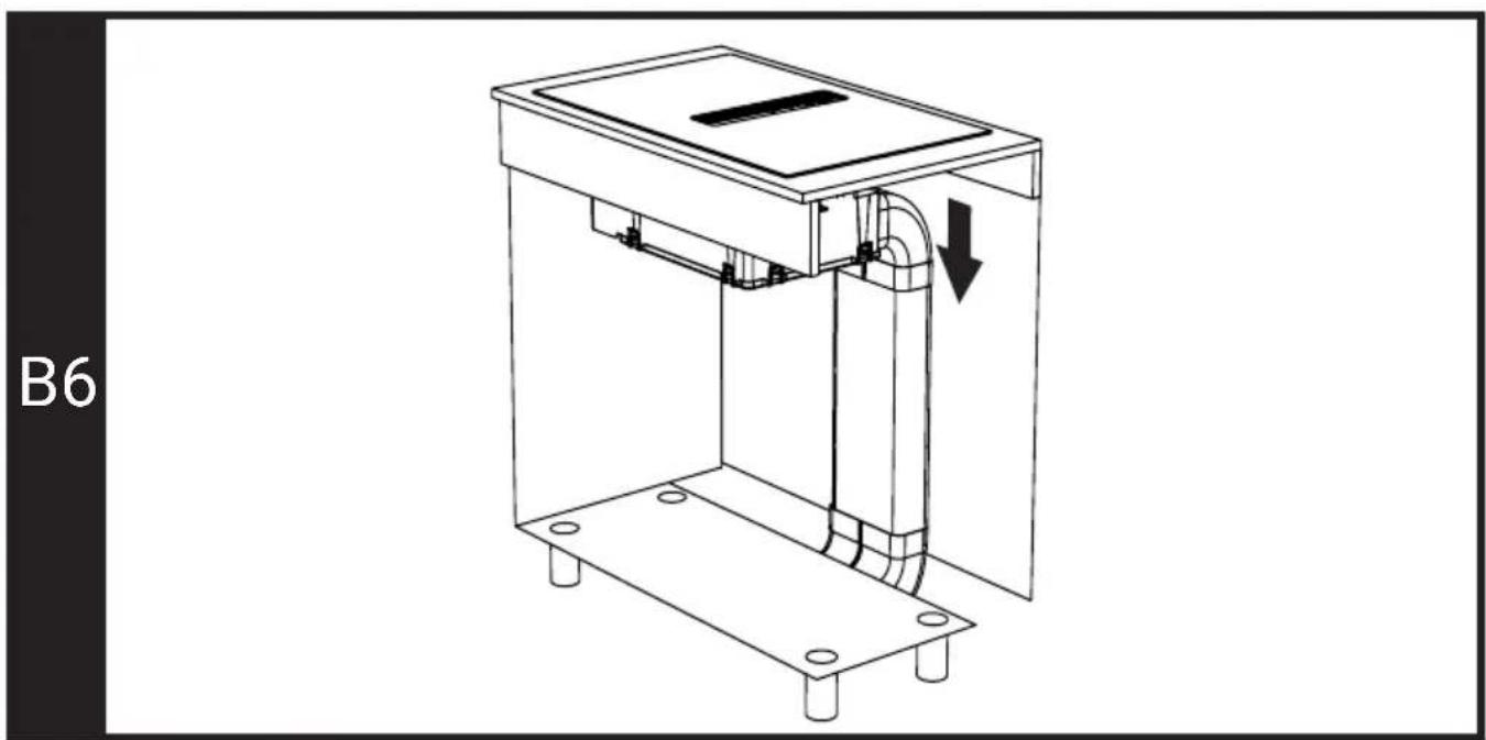
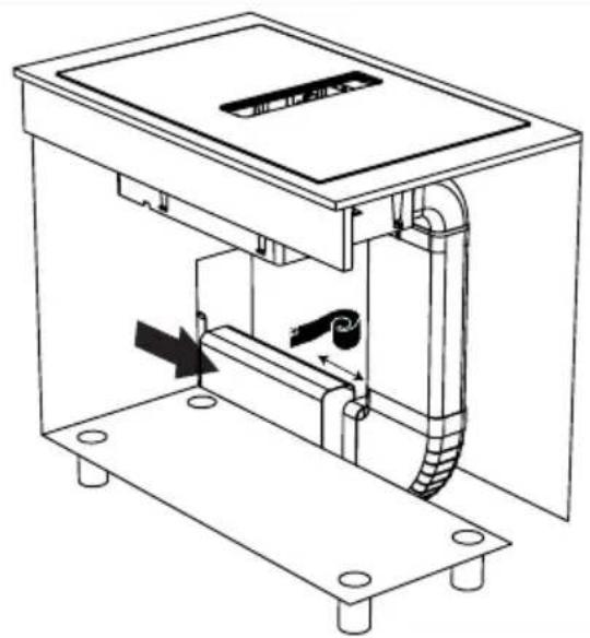
- Attach the long and corner plastics of ventilation that will direct the air to the bottom of the furniture, and attach them to the corner plastic you have attached to the back of the stove as shown in figure B5. In order to attach it to the corner plastic, you need to lift the hob a little from the back. Ventilation plastic parts must have been mounted as shown in figure B6.
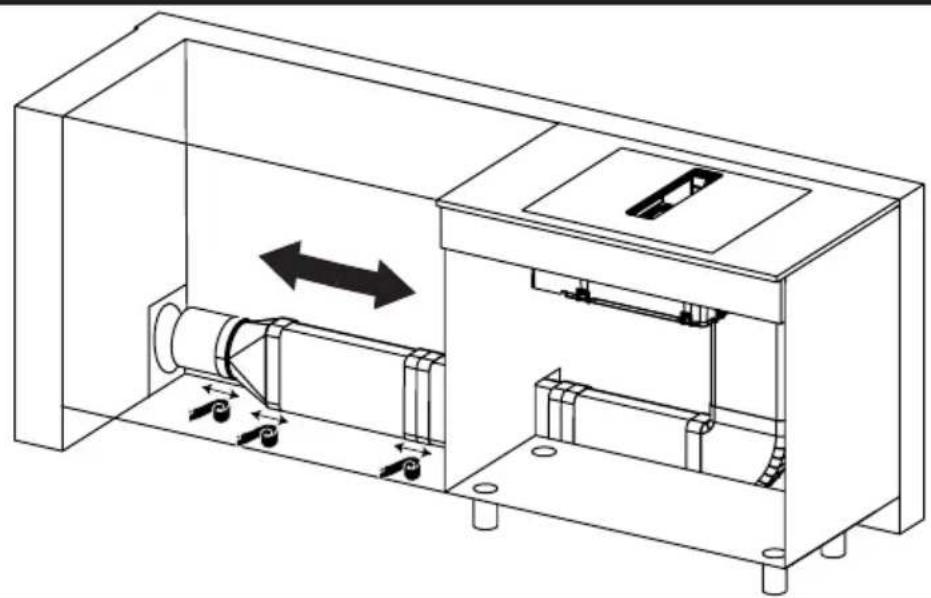
- Attach the ventilation outlet bit to the ventilation corner plastic from the bottom of your furniture as shown in figure B7.
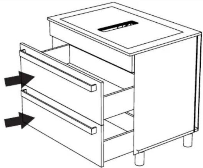
- Put your drawers back in place. (Figure B8)
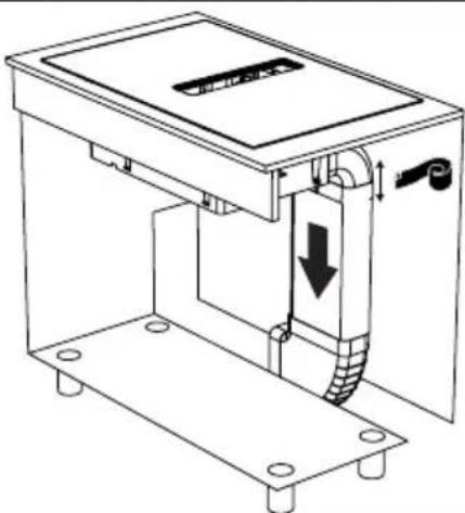
- Remove the metal oil filter by pulling it upwards. (Figure B9)
- Remove the liquid collection chamber as shown in figure B9.
- Place two units of active carbon filters to right and left as shown in figure B10.
- Place back the liquid collection chamber as shown in figure B11. Complete the installation by placing back the metal oil filter.
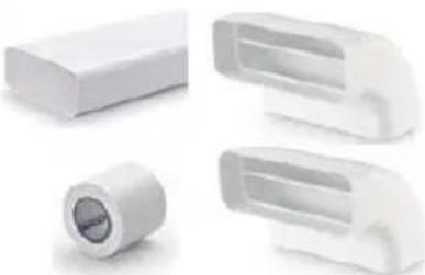
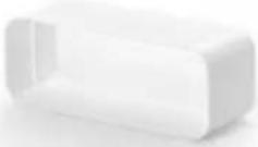
Air Routing Parts
- Air routing parts which will be used in type B installation should only be purchased from "Naber" company.
- The parts required for using type B installation with a 10 cm air routing parts are given in table B12. You may see the part code of the company for same part is in the Y column. Parts marked with * were optional for users who wanted to use air vent.
- The parts required for using type B installation with a 6 cm air routing parts are given in table B13. You may see the part code of the company for same part is in the Y column. Parts marked with * were optional for users who wanted to extend the air outlet.
C type installation (Installation with external circulation)
Preparation of the furniture on which installation will be made: (Figure C2)
Prepare your furniture according to the dimensions presented in Figure C2. Cut dimensions for flush-fit installation are also indicated in Figure C2. You need to obtain the plastic parts of the air guide described in this installation from the authorized service or authorized dealers. These parts are not supplied with the product.
Steps for C type installation
- Place the ventilation corner plastic described in Figure C3 in its slot on the back of the hob as shown in the figure.
- Completely remove the drawers of your furniture and place your stove by tilting it into its place on your furniture. (Figure C4)
- Attach the long and corner plastics of ventilation that will direct the air to the bottom of the furniture, and attach them to the corner plastic you have attached to the back of the stove as shown in figure C5. In order to attach it to the corner plastic, you need to lift the hob a little from the back. Ventilation plastic parts must have been mounted as shown in figure C5.
- Reach at your chimney using ventilation parts in accordance with its location.
- The air outlet direction shown in the installation drawings is given as an example. You may install in other directions.
Air Routing Parts
- Air routing parts which will be used in type C installation should only be purchased from "Naber" company.
- For type C installation, it should be determined which parts should be used before installed. The quantities of parts that can be used in the installation may vary according to the installation location.
- All parts that can be used in the installation are given in table C9. You may see the part code of the company for same part is in the Y column.
Electrical connection of the appliance (Figure E)
- Connect the appliance to a grounded outlet/line protected by a fuse that is compatible with the values in the "Technical specifications" table. Have the grounding installation made by a qualified electrician while using the product with or without a transformer. Our company shall not be liable for any problems arising due to the product not being earthed in accordance with the local regulations.
- Disconnect the appliance from the electric connection before starting any work on the electrical installation. Risk of electric shock.
- The appliance may only be connected to the mains electricity connection by an authorized and qualified person. The manufacturer shall not be held responsible for any damages that may occur as a result of operations performed
by unauthorized persons.
- The appliance must be installed in a way that it can be completely disconnected from the mains supply. The disconnection shall be provided by a switch built into the fixed electrical installation, according to the construction regulations.
- The bottom surface of the cooker gets hot, too, when it is in use. Electrical connections shall not contact the bottom surface, otherwise the connections may be damaged.
- Do not pass the connection cables over the hot surfaces. Otherwise, cable insulation may melt and cause fire as a result of short circuit of the cooker. If the electric cable is damaged, it must be replaced by a qualified electrician. Otherwise there is a risk of electric shock, short circuit or fire hazard!
- While performing the wiring, you shall comply with the national/local electrical regulations and shall use the appropriate socket outlet/line and plug for the cooker. In case the product's power limits exceed the current carrying capability of plug and socket outlet/line, the product must be connected to the fixed electrical installation directly without using plug and socket outlet/line.
- Make sure that fuse rating is compatible with the product.
- Connection must comply with national regulations.
- The mains supply data must correspond to the data specified on the type label of the product. You may see the type label on the bottom of the cooker.
- Power cable of your product must comply with the values presented in "Technical specifications" section.
- If the appliance shall be directly connected to the mains: If it is not possible to disconnect all poles in the mains supply, a disconnection unit with at least 3 mm contact clearance (fuse, line safety switch, contactor) shall be connected and all the poles of this disconnection unit shall be adjacent to (not above) the appliance in accordance with IEE directives. Failure to obey this instruction may cause operational problems and invalidate the product warranty.
• Additional protection by a residual current circuit breaker is recommended.
If your appliance has a cord and plug:
- Perform the electrical connection of your appliance by plugging it to a grounded socket.
If your appliance has a cord, but does not have a plug:
- Connect your appliance to the mains as specified below as per the cord type. The cord type of your appliance is specified in the "Technical Specifications" section of the operation manual.
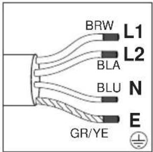
If your supply cord type is 5-conductor type, for 1-phase connection:
For single phase connection
- (BRW/BLA) Brown/Black = L (Phase)
- (BLU/GRE) Blue/Grey = N (Neutral)
- (GR/YE) Green/yellow wire = (E) ⏚ (Earthing)
If your supply cord type is 5-conductor type, for 2-phase connection:
- (BRW) Brown = L1 (Phase)
- (BLA) Black = L2 (Phase)
- (BLU/GRE) Blue/Grey = N (Neutral)
- (GR/YE) Green/yellow wire = (E) (Earthing)
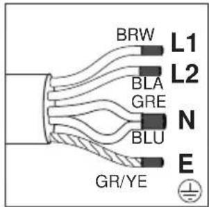
If your supply cord type is 4-conductor type, for 2-phase connection:
- (BRW) Brown = L1 (Phase)
- (BLA) Black = L2 (Phase)
- (BLU) Blue = N (Neutral)
-(GR/YE) Green/yellow wire = (E) ⏚ (Earthing)
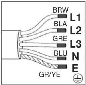
If your supply cord type is 5-conductor type, for 3-phase connection:
- (BRW) Brown = L1 (Phase)
- (BLA) Black = L2 (Phase)
- (GRE) Grey = L3 (Phase)
- (BLU) Blue = N (Neutral)
-(GR/YE) Green/yellow wire = (E) ⏚ (Earthing)
For the protection of the appliance against burning:
- Make sure that the product plug is securely plugged into the outlet to avoid arcing.
- Do not use damaged cables or extension cables.
- Ensure there is no liquid or moisture on the socket where the product plug is connected.
Final inspection
• After completing the installation, turn on the mains supply.
- Read the operation manual for the first operation of the appliance.
- Ensure that each cooking hob heats and ventilation works.
- (BRW/BLA) Braun/Schwarz = L (Phase)
-(BLU/GRE) Blau/Grau = N (Neutral)
- (GR/YE) Grüner/gelber Draht = (E) ⏻ (Earthing)
- (BRW) Braun = L1 (Phase)
- (BLA) Schwarz = L2 (Phase)
- (BLU/GRE) Blau/Grau = N (Neutral)
- (GR/YE) Grüner/gelber Draht = (E) ⏻ (Earthing)
- (BRW) Braun = L1 (Phase)
- (BLA) Schwarz = L2 (Phase)
- (BLU) Blau = N (Neutral)
- (GR/YE) Grüner/gelber Draht = (E) ⏻ (Earthing)
- (BRW) Braun = L1 (Phase)
- (BLA) Schwarz = L2 (Phase)
- (GRE) Grau = L3 (Phase)
- (BLU) Blau = N (Neutral)
- (GR/YE) Grüner/gelber Draht = (E) ⏚ (Earthing)
- (BRW/BLA) marron / noir = L (Phase)
- (BLU/GRE) bleu / gris = N (Neutre)
- (BRW) marron = L1 (Phase)
- (BLA) noir = L2 (Phase)
- (BLU/GRE) bleu / gris = N (Neutre)
- (BLU/GRE) Blå/Grå= N (Neutral)
- (GR/YE) Grøn/gul ledning = (E) ⏚ (Jordforbindelse)
Hvis din netledningstype er 5-leder type, til 2-fasetilslutning:
- (BRW) Brun = L1 (Fase)
- (BLA) Sort = L2 (Fase)
- (BLU/GRE) Blå/Grå= N (Neutral)
- (GR/YE) Grøn/gul ledning = (E) ⏚ (Jordforbindelse)
- (BRW) Brun = L1 (Fase)
- (BLA) Sort = L2 (Fase)
- (BLU) Blå = N (Neutral)
- (GR/YE) Grøn/gul ledning = (E) ⏚ (Jordforbindelse)
Hvis din netledningstype er 5-leder type, til 3-fasetilslutning:
- (BRW) Brun = L1 (Fase)
- (BLA) Sort = L2 (Fase)
- (GRE) Grå = L3 (Fase)
- (BLU) Blå = N (Neutral)
- (GR/YE) Grøn/gul ledning = (E) ⏚ (Jordforbindelse)
- (BRW) Marrone = L1 (Fase)
- (BLA) Nero = L2 (fase)
- (BRW/BLA) Bruin/Zwart = L (Fase)
- (BRW) Bruin = L1 (Fase)
- (BLA) Zwart = L2 (Fase)
- (BRW) Bruin = L1 (Fase)
- (BLA) Zwart = L2 (Fase)
- (BRW) Bruin = L1 (Fase)
- (BLA) Zwart = L2 (Fase)
- (BRW) Brun = L1 (fase)
- (BLA) Svart = L2 (fase)
- (BRW) Brun = L1 (fase)
- (BLA) Svart = L2 (fase)
- (BRW) Brun = L1 (Fas)
- (BLA) Svart = L2 (Fas)
- (BLU/GRE) Blå/Grå = N (Neutral)
- (GR/YE) Grön/gul ledning = (E) ⏚ (Jordning)
- (BRW) Brun = L1 (Fas)
- (BLA) Svart = L2 (Fas)
- (BLU) Blå = N (Neutral)
- (GR/YE) Grön/gul ledning = (E) ⏚ (Jordning)
- (BRW) braon = L1 (Faza)
- (BLA) crna = L2 (Faza)
- (BLU) plava = N (Nula)
- (GR/YE) zelena/žuta žica = (E) ⏚ (Uzemljenje)
- (BRW) braon = L1 (Faza) - (BLA) crna = L2 (Faza) - (BLU) plava = N (Nula) - (GR/YE) zelena/žuta žica = (E) ⏚ (Uzemljenje)
Ako je vaš kabl za napajanje tipa s 5 konduktora, za dvofazni priključak:
- (BRW) braon = L1 (Faza)
- (BLA) crna = L2 (Faza)
- (GRE) siva = L3 (faza)
- (BLU) plava = N (Nula)
- (GR/YE) zelena/žuta žica = (E) ⏚ (Uzemljenje)
- (BRW) braon = L1 (Faza) - (BLA) crna = L2 (Faza) - (GRE) siva = L3 (faza) - (BLU) plava = N (Nula) - (GR/YE) zelena/žuta žica = (E) ⏚ (Uzemljenje)
Za zaštitu uređaja od opekotina:
- Provjerite da li je utikač proizvoda čvrsto priključen u utičnicu da se izbjegne stvaranje luka.
- Ne koristite oštećene kablove ili produžne kablove.
- Provjerite nema tečnosti ili vlage na utičnici u koju je spojen utikač proizvoda.
Završna kontrola
- (BRW) Marrón = L1 (Fase)
- (BLA) Negro = L2 (Fase)
- (GRE) Gris = L3 (Fase)
- (BLU) Azul = N (Neutro)
- (GR/YE) Cable verde/amarillo = (E) ⏚ (Puesta a tierra)
- (BLU/GRE) sinine/hall = N (null)
- (GR/YE) roheline/kollane juhe= (E) ⏻ (maandus)
- (BLA) must = L2 (faas)
- (BLU/GRE) sinine/hall = N (null)
- (GR/YE) roheline/kollane juhe= (E) ⏻ (maandus)
- (BRW/BLA) Cokelat/Hitam = L (Fase)
- (BLU/GRE) Biru/Abu-abu = N (Netral)
- (GR/YE) Kabel hijau/kuning = (E) ⏚ (Pembumian)
- (BRW) Cokelat = L1 (Fase)
- (BLA) Hitam = L2 (Fase)
- (BLU/GRE) Biru/Abu-abu = N (Netral)
- (GR/YE) Kabel hijau/kuning = (E) ⏚ (Pembumian)
- (BRW) Cokelat = L1 (Fase)
- (BLA) Hitam = L2 (Fase) (BLU) Biru = N (Netral)
- (GR/YE) Kabel hijau/kuning = (E) ⏚ (Pembumian)
- (BRW) Cokelat = L1 (Fase)
- (BLA) Hitam = L2 (Fase)
- (GRE) Abu-abu = L3 (Fase) (BLU) Biru = N (Netral)
- (GR/YE) Kabel hijau/kuning = (E) ⏻ (Pembumian)
- (BRW) Castanho = L1 (Fase)
- (BLA) Preto = L2 (Fase)
- (BLU) Azul = N (Neutro)
- (BRW) Castanho = L1 (Fase)
- (BLA) Preto = L2 (Fase)
- (GRE) Cinzento = L3 (Fase)
- (BLU) Azul = N (Neutro)
- (GR/YE) Fio Verde/amarelo = (E) (Terra)
- (GR/YE) teli jeshil/i verdhë = (E) ⏻ (tokëzimi)
- (GR/YE) teli jeshil/i verdhë = (E) ⏚ (tokëzimi)
- (GR/YE) teli jeshil/i verdhë = (E) ⏚ (tokëzimi)
- (GR/YE) teli jeshil/i verdhë = (E) ⏚ (tokëzimi)