ZVA-M90AS290 - Basket Zephyr - Free user manual and instructions
Find the device manual for free ZVA-M90AS290 Zephyr in PDF.

User questions about ZVA-M90AS290 Zephyr
0 question about this device. Answer the ones you know or ask your own.
Ask a new question about this device
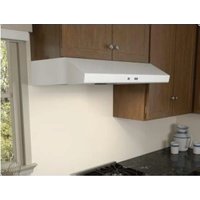
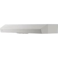
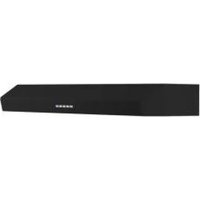
Download the instructions for your Basket in PDF format for free! Find your manual ZVA-M90AS290 - Zephyr and take your electronic device back in hand. On this page are published all the documents necessary for the use of your device. ZVA-M90AS290 by Zephyr.
USER MANUAL ZVA-M90AS290 Zephyr
natural_image
Technical line drawing of a rectangular enclosure with a circular top and mounting holes (no text or symbols)
RANGE HOOD - Installation instructions
ENGLISH......3
FRANÇAIS......30
Table of Contents
SAFETY INSTRUCTIONS ...... pag. 4
LIST OF MATERIALS ...... pag. 9
DUCTING CALCULATION SHEETS....pag. 10
HOODSPECIFICATION....pag.11
INSTALLATION
-INSTALLATION ...... pag. 12
- DUCTING OPTIONS ...... pag. 20
- MOUNTING THE RANGE HOOD ...... pag. 21
- POWER SUPPLY CONNECTION ...... pag. 22
CONTROL....pag. 23
MAINTENANCE ...... pag. 24
WIRING DIAGRAMS ...... pag. 25
LIST OF PARTS AND ACCESSORIES ...... pag. 27
WARRANTY ...... pag. 28
Safety instructions 1/4
■ IMPORTANT SAFETY INSTRUCTIONS
■ READ AND SAVE THESE INSTRUCTIONS
■ PLEASE READ ENTIRE INSTRUCTIONS BEFORE PROCEEDING.
■ IMPORTANT: Save these Instructions for the Local Electrical Inspectors use.
■ INSTALLER: Please leave these Instructions with this unit for the owner.
■ OWNER: Please retain these instructions for future reference.
■ Take care when using cleaning agents or detergents.
■ Suitable for use in household cooking area.
■ WARNING - To reduce the risk of fire or electric shock, do not use this fan with any Solid-State Speed Control Device.
■ CAUTION - To reduce risk of fire and to properly exhaust air, be sure to duct air outside – Do not vent exhaust air into spaces within walls or ceilings or into attics, crawl spaces, or garages.
■ CAUTION - For general ventilating use only. Do not use to exhaust hazardous or explosive materials and vapors.
■ CAUTION - To avoid motor bearing damage and noisy and/or unbalanced impellers, keep drywall spray, construction dust, etc. off power unit.
■ CAUTION - Please read specification label on product for further information and requirements.
■ WARNING – TO REDUCE THE RISK OF FIRE, ELECTRIC SHOCK, OR INJURY TO PERSONS, OBSERVE THE FOLLOWING:
A. Use this unit only in the manner intended by the manufacturer. If you have questions, contact the manufacturer.
B. Before servicing or cleaning unit, switch power off at service panel and lock the service disconnecting means to prevent power from being switched on accidentally. When the service disconnecting means cannot be locked, securely fasten a prominent warning device, such as a tag, to the service panel.
C. To reduce the risk of fire, electric shock or injury to persons, do not use replacement parts that have not been recommended by the manufacturer (e.g. parts made at home using a 3D printer).
Safety instructions 2/4
■ WARNING - TO REDUCE THE RISK OF A RANGE TOP GREASE FIRE:
A. Never leave surface units unattended at high settings. Boilovers cause smoking and greasy spillovers that may ignite. Heat oils slowly on low or medium settings.
B. Always turn hood ON when cooking at high heat or when flambeing foods (i.e. Crepes Suzette, Cherries Jubilee, Peppercorn Beef Flambè).
C. Clean ventilating fans frequently. Grease should not be allowed to accumulate on fan or filter.
D. Use proper pan size. Always use cookware appropriate for the size of the surface element.
E. Keep fan, filters and grease laden surface clean.
F. Use high range setting on range only when necessary. Heat oil slowly on low to medium setting.
G. Don't leave range unattended when cooking.
H. Always use cookware and utensils appropriate for the type and amount off food being prepared.
■ WARNING – TO REDUCE THE RISK OF INJURY TO PERSONS IN THE EVENT OF A RANGE TOP GREASE FIRE, OBSERVE THE FOLLOWINGa:
A. SMOTHER FLAMES with a close-fitting lid, cookie sheet, or metal tray, then turn off the burner. BE CAREFUL TO PREVENT BURNS. If the flames do not go out immediately, EVACUATE AND CALL THE FIRE DEPARTMENT.
B. NEVER PICK UP A FLAMING PAN – You may be burned.
C. DO NOT USE WATER, including wet dishcloths or towels – a violent steam explosion will result.
D. Use an extinguisher ONLY if:
- You know you have a Class ABC extinguisher, and you already know how to operate it.
- The fire is small and contained in the area where it started.
- The fire department is being called.
- You can fight the fire with your back to an exit.
^a Based on “kitchen firesafety tips” published by NFPA
Proper maintenance of the Range Hood will assure proper performance of the unit.
■ INSTALLATION INSTRUCTIONS
WARNING – TO REDUCE THE RISK OF FIRE, ELECTRIC SHOCK, OR INJURY TO PERSONS, OBSERVE THE FOLLOWING:
Safety instructions 3/4
A. Installation work and electrical wiring must be done by qualified person(s) in accordance with all applicable codes and standards, including fire-rated construction.
B. Sufficient air is needed for proper combustion and exhausting of gases through the flue (chimney) of fuel burning equipment to prevent back drafting. Follow the heating equipment manufacturer's guideline and safety standards such as those published by the National Fire Protection Association (NFPA), and the American Society for Heating, Refrigeration and Air Conditioning Engineers (ASHRAE), and the local code authorities.
C. When cutting or drilling into wall or ceiling, do not damage electrical wiring and other hidden utilities.
D. Ducted fans must always be vented to the outdoors.
E. This unit must be grounded.
■ WARNING - TO REDUCE THE RISK OF FIRE, USE ONLY METAL DUCTWORK.
■ WARNING - UNDER CERTAIN CIRCUMSTANCES DOMESTIC APPLIANCES MAY BE DANGEROUS.
A. Do not check filters with hood working.
B. Do not touch the lamps after a prolonged use of the appliance.
C. No food must be cooked flambè underneath the hood.
D. The use of an unprotected flame is dangerous for the filters and could cause fires.
E. Watch constantly the fried food in order to avoid the cooking oil flares up.
F. Before performing any maintenance operation, disconnect the hood from the electrical service.
■ The manufacturers will not to accept any responsibility for eventual damages, because of failure to observe the above instructions.
Electrical Requirements
Important:
- Observe all governing codes and ordinances.
- It is the customer's responsibility to be aware of these below:
- To contact a qualified electrical installer.
- To assure that the electrical installation is adequate and in conformance with National Electrical Code, ANSI/NFPA 70 latest edition* or CSA standards C22.1-94, Canadian Electrical Code, Part 1 and C22.2 No.0-M91 - latest edition** and all local codes and ordinances.
- If codes permit and a separate ground wire is used, it is recommended that a qualified electrician determine that the ground path is adequate.
Safety instructions 4/4
- Do not ground to a gas pipe.
- Check with a qualified electrician if you are not sure the range hood is properly grounded.
- Do not have a fuse in the neutral or ground circuit.
- This appliance requires a 120V 60Hz electrical supply and connected to an individual properly grounded branch circuit protected by a 15 or 20 ampere circuit breaker or time delay fuse. Wiring must be 2 wire with ground. Please also refer to Electrical Diagram on product.
- A cable locking connector (not supplied) might also be required by local codes. Check with local requirements, purchase and install appropriate connector if necessary.
* National Fire Protection Association Batterymarch Park, Quincy, Massachusetts 02269
** CSA International 8501 East Pleasant Valley Road, Cleveland, Ohio 44131-5575
Federal Communication Commission Interface Statement
- This equipment has been tested and found to comply with the limits for a Class B digital device, pursuant to Part 15 of the FCC Rules. These limits are designed to provide reasonable protection against harmful interference in a residential installation.
- This equipment generates, uses and can radiate radio frequency energy and, if not installed and used in accordance with the instructions, may cause harmful interference to radio communications. However, there is no guarantee that interference will not occur in a particular installation. If this equipment does cause harmful interference to radio or television reception, which can be determined by turning the equipment off and on, the user is encouraged to try to correct the interference by one of the following measures:
- Reorient or relocate the receiving antenna.
- Increase the separation between the equipment and receiver.
- Connect the equipment into an outlet on a circuit different from that to which the receiver is connected.
- Consult the dealer or an experienced radio/TV technician for help.
SAFETY PRECAUTION
- Take care when the cooker hood is operating simultaneously with an open fireplace or burner that depend on the air in the environment and are supplied by other than electrical energy, as the cooker hood removes the air from the environment which a burner or fireplace need for combustion. The negative pressure in the environment must not exceed 4Pa (4x10⁻⁵ bar). Provide adequate ventilation in the environment for a safe operation of the cooker hood. Follow the local laws applicable for external air evacuation.
Safety instructions 5/5
Before connecting the model to the electricity network:
- Control the data plate (positioned inside the appliance) to ascertain that the voltage and power correspond to the network and the socket is suitable. If in doubt ask a qualified electrician.
- If the power supply cable is damaged, it must be replaced with another cable or a special assembly, which may be obtained direct from the manufacturer or from the Technical Assistance Centre.
2. Warning!
In certain circumstances electrical appliances may be a danger hazard.
A) Do not check the status of the filters while the cooker hood is operating.
B) Do not touch bulbs or adjacent areas, during or straight after prolonged use of the lighting installation.
C) Flambè cooking is prohibited underneath the cooker hood.
D) Avoid free flame, as it is damaging for the filters and a fire hazard.
E) Constantly check food frying to avoid that the overheated oil may become a fire hazard.
F) Disconnect the electrical plug prior to any maintenance.
G) This appliance can be used by children aged from 8 years and above and persons with reduced physical, sensory or mental capabilities or lack of experience and knowledge if they have been given supervision or instruction concerning use of the appliance in a safe way and understand the hazards involved. Children shall not play with the appliance. Cleaning and user maintenance shall not be made by children without supervision.
H) Young children should be supervised to ensure they do not play with the appliance.
I) There shall be adequate ventilation of the room when the rangehood is used at the same time as appliances burning gas or other fuels.
L) There is a risk of fire if cleaning is not carried out in accordance with the instructions.
INSTALLATION INSTRUCTIONS
- Assembly and electrical connections must be carried out by specialised personnel.
- Wear protective gloves before proceeding with the installation.

WARNING Prop. 65 Warning for California Residents: This product may contain chemicals known to the State of California to cause cancer, birth defects, or other reproductive harm.
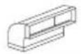
List of Materials
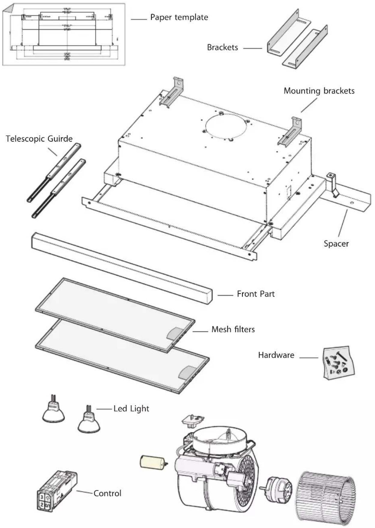
text_image
Paper template Brackets Mounting brackets Spacer Telescopic Guide Front Part Mesh filters Hardware Led Light ControlDucting Calculation Sheet
| Duct pieces | Equivalent number length x used = | Total | |
 | 3- 1/4" x 10" Rect., straight | 1 Ft. x ( ) = | Ft. |
 | 6", 7", 8", 10" Round, straight | 1 Ft. x ( ) = | Ft. |
 | 3- 1/4" x 10" Rect. 90° elbow | 15 Ft. x ( ) = | Ft. |
 | 3- 1/4" x 10" Rect. 45° elbow | 9 Ft. x ( ) = | Ft. |
 | 3- 1/4" x 10" Rect. 90° flat elbow | 24 Ft. x ( ) = | Ft. |
 | 7" to 6" or 8" to 7" Round tapered reducer | 25 Ft. x ( ) = | Ft. |
 | 6", 7", 8" Round in-line damper | 15 Ft. x ( ) = | Ft. |
 | 6", 7", 8", 10" Round, 90° elbow | 15 Ft. x ( ) = | Ft. |
 | 6", 7", 8", 10" Round, 45° elbow | 9 Ft. x ( ) = | Ft. |
| Subtotal column 1 = | Ft. | ||
Maximum Duct Length: For satisfactory air movement, the total duct length should not exceed 150 equivalent feet.
| Duct pieces | Equivalent number length x used = | Total | |
 | 3- 1/ 4" x 10" Rect. to 6" round transition | 5 Ft. x ( ) = | Ft. |
 | 3- 1/ 4" x 10" Rect. to 6" round transition 90° elbow | 20 Ft. x ( ) = | Ft. |
 | 6" round to 3- 1/ 4" x 10" rect. transition | 1 Ft. x ( ) = | Ft. |
 | 6" round to 3- 1/ 4" x 10" rect. transition 90° elbow | 16 Ft. x ( ) = | Ft. |
 | 7" round to 3 1/ 4" x 10" rect. transition | 8 Ft. x ( ) = | Ft. |
| -KA54] | 7" round to 3- 1/ 4" x 10" rect. transition 90° elbow | 23 Ft. x ( ) = | Ft. |
 | 3- 1/ 4" x 10" Rect. wall cap with damper | 30 Ft. x ( ) = | Ft. |
 | 6", 7", 8", 10" Round, wall cap with damper | 30 Ft. x ( ) = | Ft. |
 | 6", 7", 8", 10" Round roof cap | 30 Ft. x ( ) = | Ft. |
| Subtotal column 2 = Subtotal column 1 = Total ductwork = | Ft. | ||
| Ft. | |||
| Ft. | |||
Hood Specifications
front of hood
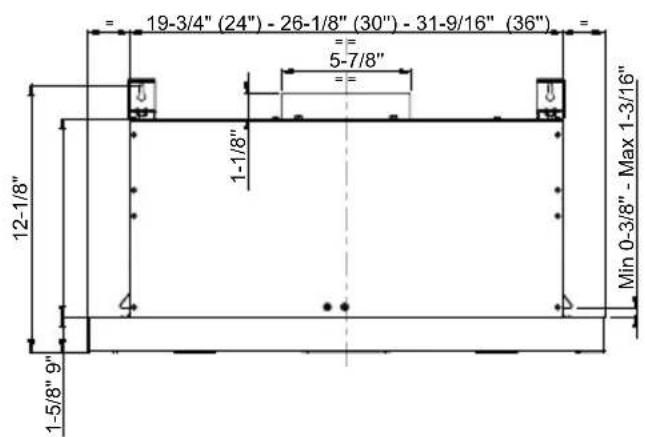
text_image
= 19-3/4" (24") - 26-1/8" (30") - 31-9/16" (36") 5-7/8" 1-1/8" 12-1/8" 1-5/8" 9" Min 0-3/8" - Max 1-3/16"back of hood
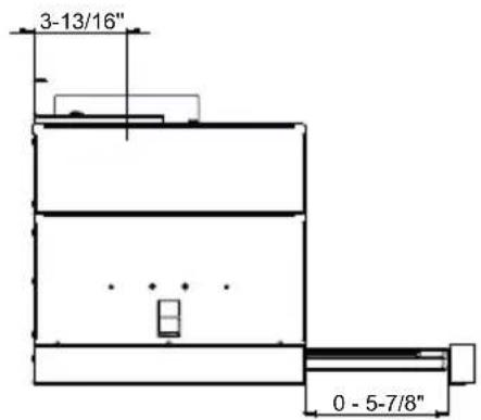
text_image
3-13/16" 0 - 5-7/8"top of hood
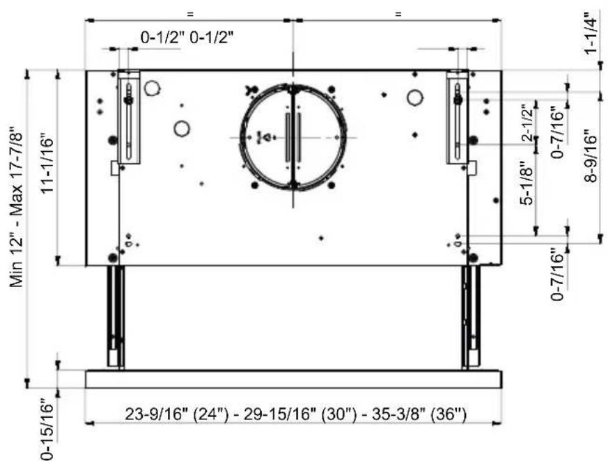
text_image
0-1/2" 0-1/2" 11-1/16" Min 12" - Max 17-7/8" 0-15/16" 23-9/16" (24") - 29-15/16" (30") - 35-3/8" (36") 1-1/4" 5-1/8" 2-1/2" 0-7/16" 0-7/16" 8-9/16"Fig.1
Installation
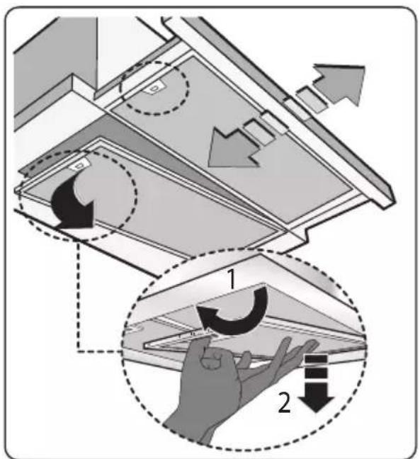
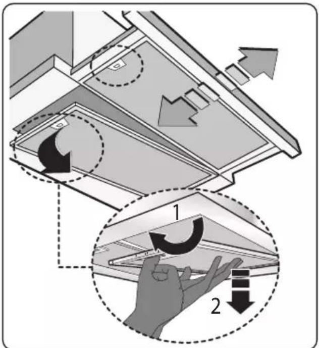
Before proceeding with installation operations, remove the grease filter (Fig.3) in order to make handling the device easier.
This product can be installed in 3 different ways, depending on the model and on your requirements:
1- Installing the hood on the bottom shelf of a wall cabinet.
2- Installing the hood into a wall cabinet using a horizontal divider for support.
3- 30" Hoods Only – Installing the hood onto the side wall of a wall cabinet.
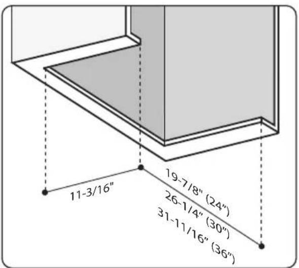
text_image
11-3/16" 19-7/8" (24") 26-1/4" (30") 31-11/16" (36")Fig.2
text_image
Diagram illustrating airflow or ventilation process with labeled arrows and circular indicators, showing structural changes in a building interior.Fig.3
Installation
text_image
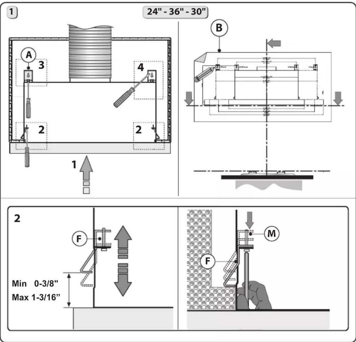
1 24" - 36" - 30" A 3 4 B 2 2 1 2 Min 0-3/8" Max 1-3/16" F M FFig.4
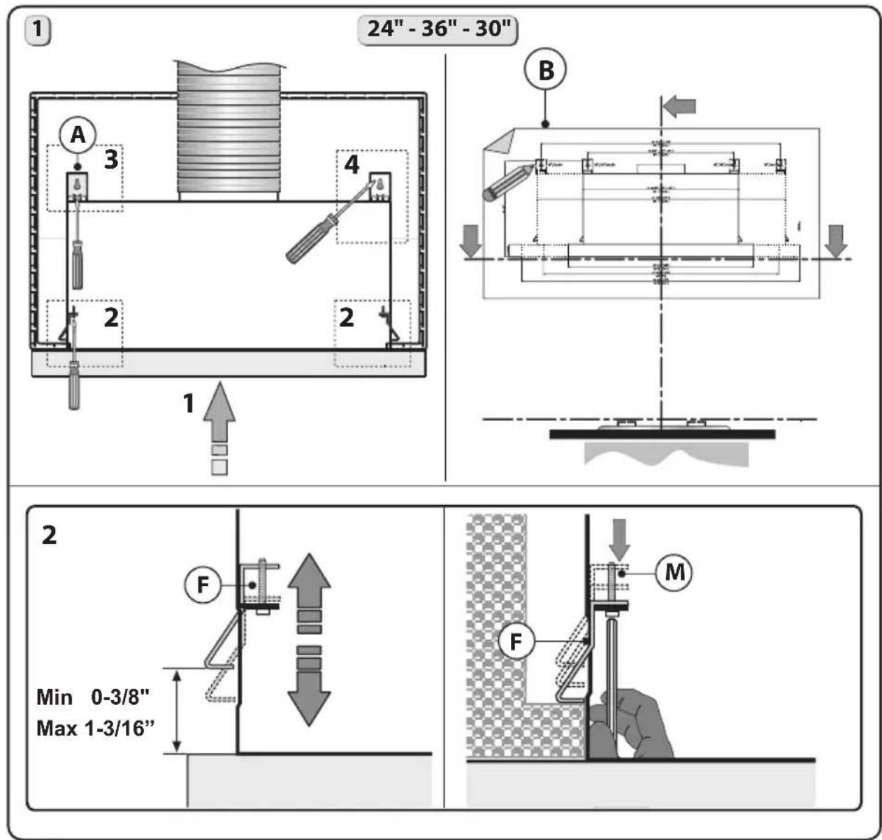
1. INSTALLING THE HOOD ON THE BOTTOM SHELF OF THE WALL CABINET:
- Remove pin Y from bracket A. (Pin Y can be discarded.) Then place the insert X on the slot of the bracket A, as indicated in Fig. 4 - step 3.
Match the C screws with the L washer and attach the A bracket to the cabinet as indicated in Fig. 4 - step 3.1. Do not completely tighten screws C to allow the bracket to slide back and forth.
- Position template B on the wall cabinet, bearing in mind the measurements indicated in Fig.s 1 and 2 and the minimum distance from the cooktop.
- Mark the references to fasten brackets A to the wall cabinet, as indicated in Fig. 4.
-
Make sure the thickness of the wall cabinet is within the parameters indicated in Fig. 4 - step 2.
-
Insert the hood into the wall cabinet, ensuring the 2 side springs F are connected correctly, as the weight of the unit will rest on these springs. Fasten the hood
to the wall cabinet using the screwdriver and the relative screws M and tighten until the hood is firmly against the wall cabinet (Fig. 4 - step 2).
- Remove pin Y from bracket A. (Pin Y can be discarded.) Then place the insert X on the slot of the bracket A, as indicated in Fig. 4 - step 3.
- After any adjusting to ensure the bracket touches the wall cabinet, tighten the bracket to the body (Fig. 4 - step 3.3).
- Fasten screw D to the wall cabinet as indicated in Fig. 4 - step 4.
- Once you have fastened the hood to the wall cabinet, adjust the spacer L, with the screws P, to make the device line up with the rear wall cabinet (Fig. 4 - step 5).
IMPORTANT - The range hood must be secured to wall studs or use drywall anchors capable of supporting 75 lbs.
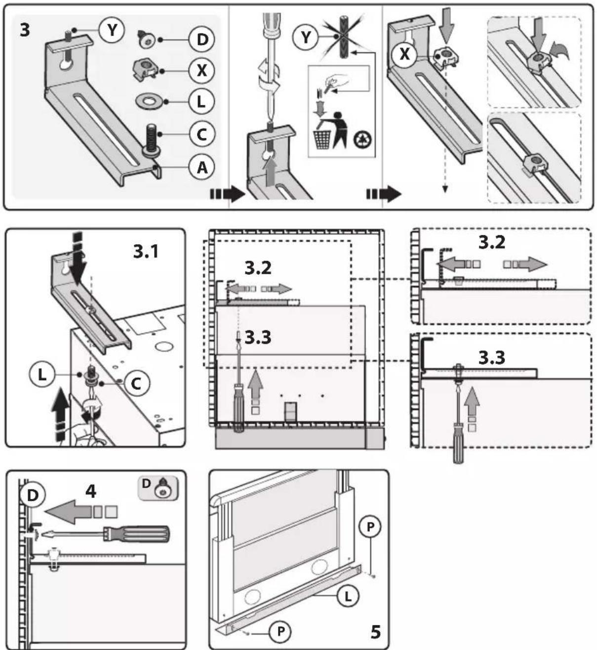
Fig.4
Installation
2. INSTALLATION OF THE HOOD INTO A WALL CABINET USING A HORIZONTAL DIVIDER FOR SUPPORT.
Follow the steps below:
1 - Check the measurements indicated in Fig.s 1 and 2 and the minimum distance from the cooktop, before installing the hood on the support shelf.
2 - Install a support shelf a the width of the cabinet interior at (9" from the bottom) (1/2" thick).
3 - Make sure the thickness of the wall cabinet is within the parameters indicated in Fig. 4 - step 2.
4 - Install the hood in the wall cabinet and make sure the 2 side springs F are connected correctly. Fasten the hood to the wall cabinet using the screwdriver and the relative screws M and tighten until the device is firmly against the wall cabinet (Fig. 4 - step 2).
5 - Fasten the hood to the upper support shelf as indicated in Fig. 5 - step 6. - Once you have fastened the hood to the wall cabinet, adjust the spacer L, with screws P, to fill the gap between the hood and rear wall. (Fig. 4 - step 5).
IMPORTANT - The range hood must be secured to wall studs or using drywall anchors capable of supporting 75 lbs.
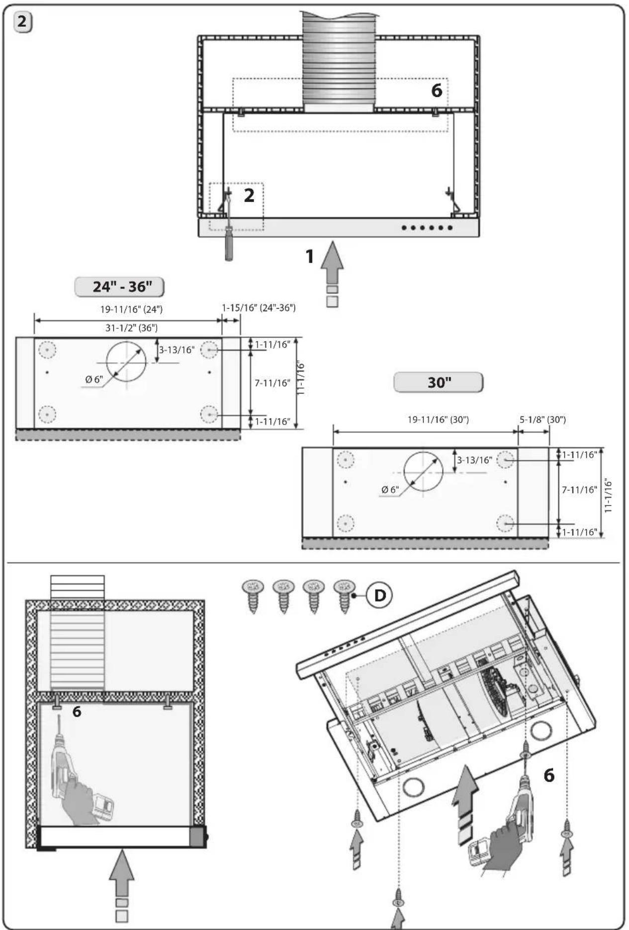
Fig.5
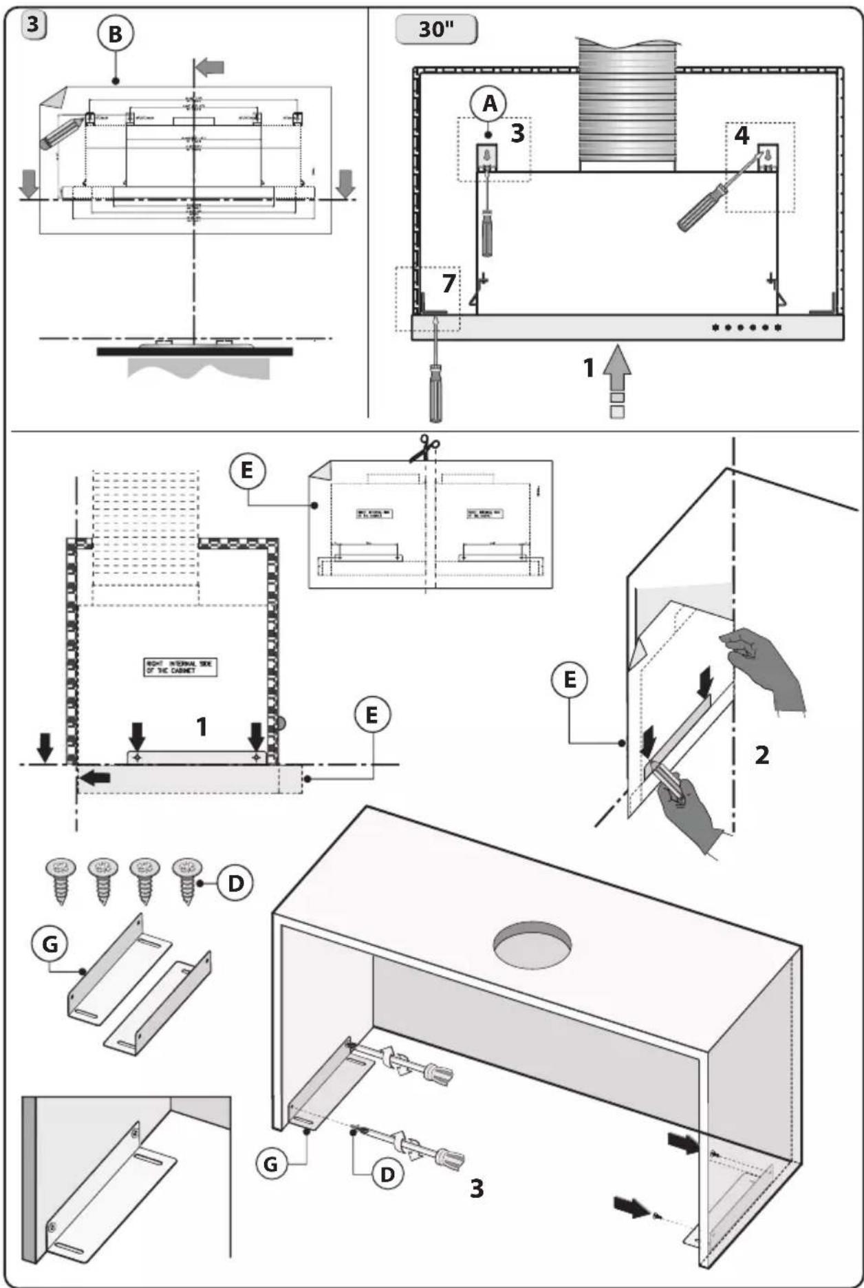
Fig.6
Installation
text_image
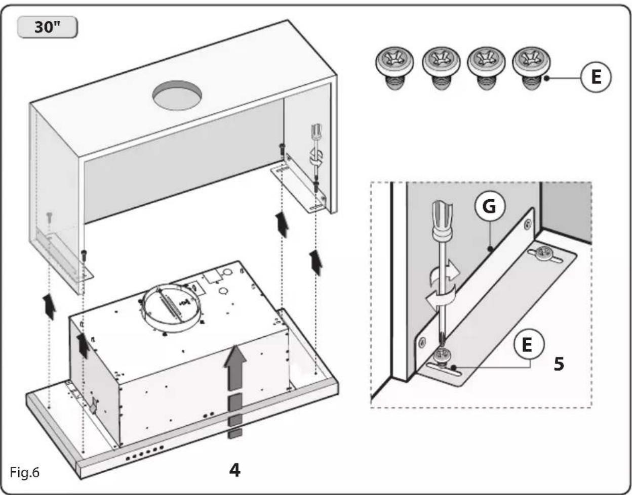
30" Fig.6 4 E G E 5- 30" HOODS ONLY – INSTALLATION OF THE HOOD ON THE LOWER PART OF THE WALL CABINET USING PROVIDED METAL BRACKETS.
This model includes side installation to the wall cabinet by using 2 brackets B (Fig. 6 besides steps 3-4, indicated in Fig 4).
1- Position template B on the wall cabinet, bearing in mind the measurements indicated in Fig. 1-2 and the minimum distance from the cooktop.
- Mark the references to fix brackets A to the wall cabinet, as indicated in Fig. 6.
2 - Position the second template E on the side of the wall cabinet and make sure that the line matches up with that traced in Fig. 6 - step 1.
3 - Mark and drill the 4 fixing holes (Fig. 6 - step 2).
- Fasten the 2 brackets G to the wall cabinet using the 4 screws D (Fig. 6 - step 3).
- Fasten the hood to bracket G using the 4 screws E (Fig. 6 - step 4-5).
4- Remove pin Y from bracket A. (Pin can be discarded.) Then place the insert X on the slot of the bracket A, as indicated in Fig. 4 - step 3.
- Match the C screws with the L washer and fix the A bracket to the cabinet as indicated in Fig. 4 - step 3.1. Pay attention not to completely tighten screws C before the bracket firmly reaches the wall cabinet (Fig. 4 - step 3.2). After any adjusting, tighten the bracket to the body (Fig. 4 - step 3.3).
- Fasten screw D to the wall cabinet as indicated in Fig. 4 - step 4.
- Once you have fastened the hood to the wall cabinet, adjust the spacer L, with screws P, to make the device line up the rear wall cabinet (Fig. 4 - step 5).
IMPORTANT - The range hood must be secured to wall studs or using drywall anchors capable of supporting 75 lbs.
Installation - Ducting Options
■ WARNING FIRE HAZARD
NEVER exhaust air or terminate duct work into spaces between walls, crawl spaces, ceiling, attics or garages.
All exhaust must be ducted to the outside, unless using the recirculating option.
Use single wall rigid Metal ductwork only.
Fasten all connections with sheet metal screws and tape all joints w/ certified Silver Tape or Duct Tape.
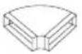
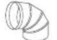
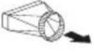
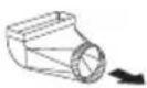
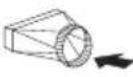
Some Ducting Options
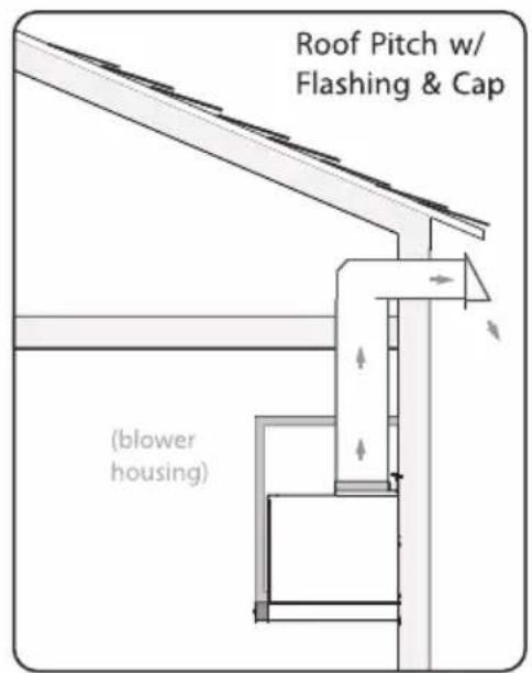
text_image
Roof Pitch w/ Flashing & Cap (blower housing)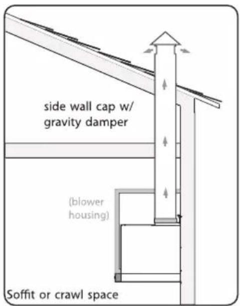
text_image
side wall cap w/ gravity damper (blower housing) Soffit or crawl space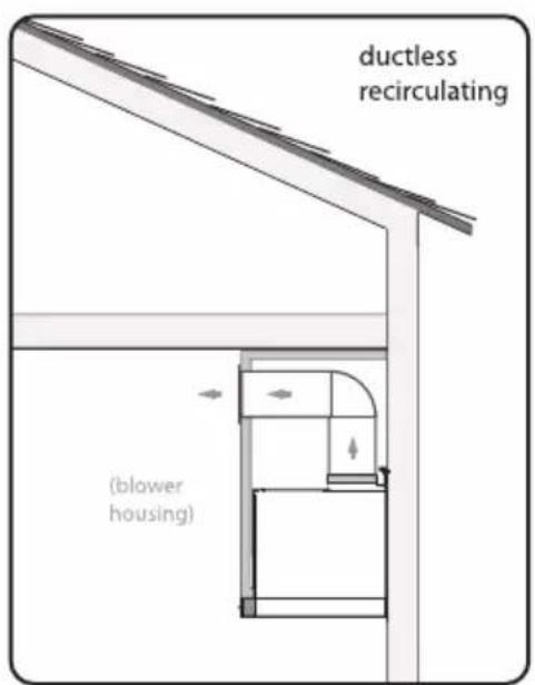
text_image
ductless recirculating (blower housing)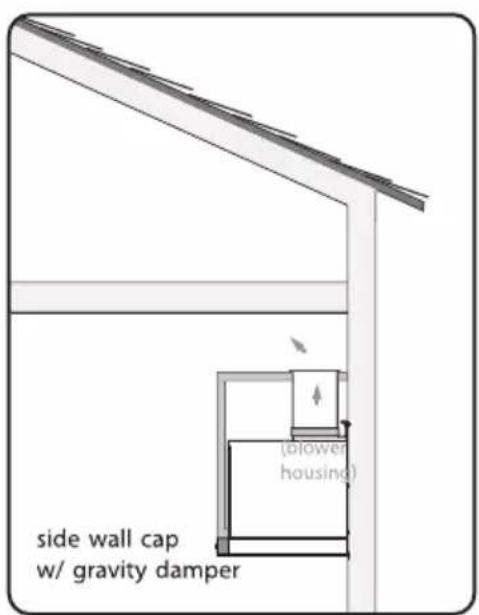
text_image
side wall cap w/ gravity damper (blower housing)Installation - Mounting the Range Hood
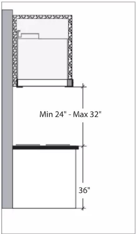
■ MOUNTING HEIGHTS
The range hood must be installed at a minimum height of 24 inches (61cm) from the cooking surface. If a connecting duct work composed of two parts is used, the upper part must be placed outside the lower part. Do not connect the range hood duct to the same duct used to exhaust hot air or fumes from another appliance. Before proceeding with the assembly instructions remove the decorative mesh filters so that the range hood is easier to handle.
text_image
Min 24" - Max 32" 36"Installation - Power Supply Connection
GENERAL
- Carefully read the following important information regarding installation safety and maintenance. Keep this information booklet accessible for further consultations.
• Power Supply Connection:
For connection to the power supply refer to:
BLACK = L line
WHITE = N neutral
GREEN/YELLOW = G ground
- A double-pole switch properly rated must be installed to provide the range hood power supply disconnection.
- Connect the electrical conduit to the Field Wiring Compartment using listed conduit fittings.
- Carry out the power supply connection in accordance with the national electric code, ANSI/NFPA 70-1999.
- Insert the wires into the box, then close the box cover, securing it using the s c re ws t ha t were previously removed.
The appliance should be installed at a minimum height of 24" up to a maximum height of 32" for optimal performance. If a connection ductwork composed of two parts is used, the upper part must be placed outside the lower part. Do not connect the range hood exhaust duct air to the same duct air used to exhaust hot air or fumes from other appliances other than electrical.
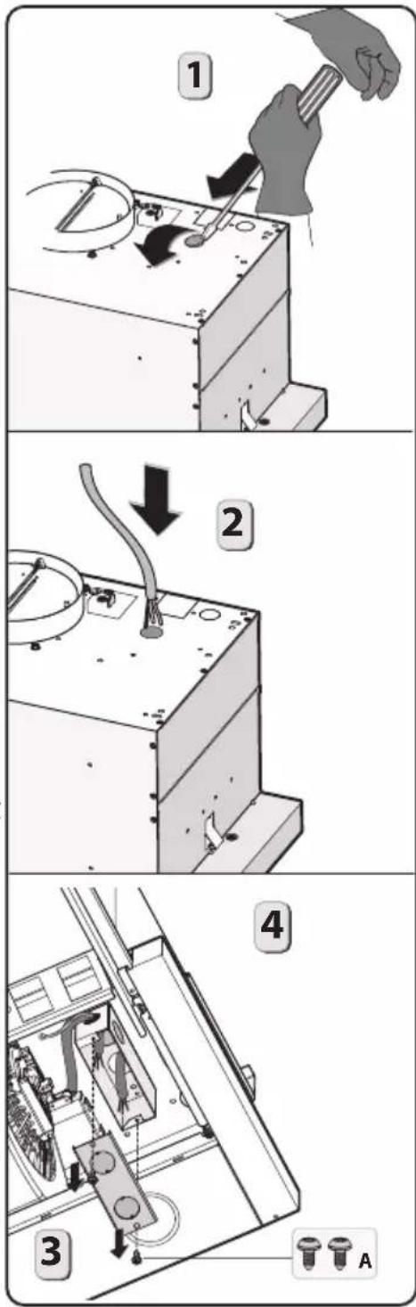
text_image
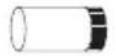
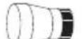
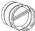
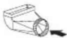
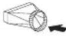
Technical diagram showing four-step installation of a mechanical device with labeled parts and directional arrows.- In the FILTERING version it is necessary to apply a metal air exhaust tube M with a minimum length of 15", connected to the flange of the collector. It must be positioned vertically and fastened to a specific opening made on the top part of the cabinet.
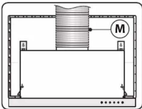
natural_image
Diagram of a mechanical setup with a cylindrical component and labeled mass M, enclosed in a rectangular frame (no text or symbols beyond label)Control

text_image
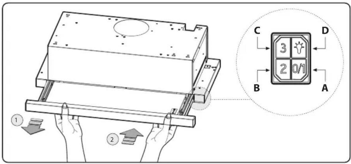
Technical diagram showing hands operating a mechanical component with labeled parts and a close-up of a 3x10/1 display panel.- Mechanical controls (for model ZVA-E30AS290 - ZVA-M60AS290 - ZVA-M90AS290) 290 CFM, the symbols are shown below:
A = FIRST SPEED Off/On Switch
B = SECOND SPEED Switch
C = SECOND SPEED Switch.
D = Light On/Off Switch
- Mechanical controls (for model ZVA-E30AS - ZVA-M90AS) 600 CFM, the symbols are shown below:
A = FIRST SPEED Off/On Switch
B = SECOND SPEED Switch
C = THIRD SPEED Switch.
D = Light On/Off Switch
FCC Caution: To assure continued compliance, any changes or modifications not expressly approved by the party responsible for compliance could void the user's authority to operate this equipment. (Example - use only shielded interface cables when connecting to computer or peripheral device. This device complies with Part 15 of the FCC Rules. Operation is subject to the following two conditions. (1) This device may not cause harmful interference, and (2) This device must accept any interference received, including interference that may cause undesired operation.
Maintenance
- It is recommended to operate the appliance prior to cooking. It is recommended to leave the appliance in operation for 5 minutes after cooking is completed in order to completely eliminate cooking vapors and odors. The proper function of the range hood is conditioned by the regularity of maintenance.
- The decorative mesh filters capture the grease particles suspended in the air and are therefore subject to clogging because of frequent use. In order to prevent a fire hazard, it is recommended to clean the filter a minimum of every 2 months.
Clean the range hood by carrying out the following instructions:
- Remove the filters from the range hood and wash them in a solution of water and neutral liquid detergent, leaving to soak.
- Rinse thoroughly with warm water and leave to dry.
- Filters may also be washed in the dishwasher at the lowest setting. The filters may alter in color after several washes but is not cause for replacement.
- Clean the blower and other surfaces of the range hood regularly using a cloth moistened with denatured alcohol or non abrasive liquid detergent.
Wiring Diagram
For Models ZVA-E30AS290, ZVA-M60AS290, ZVA-M90AS290
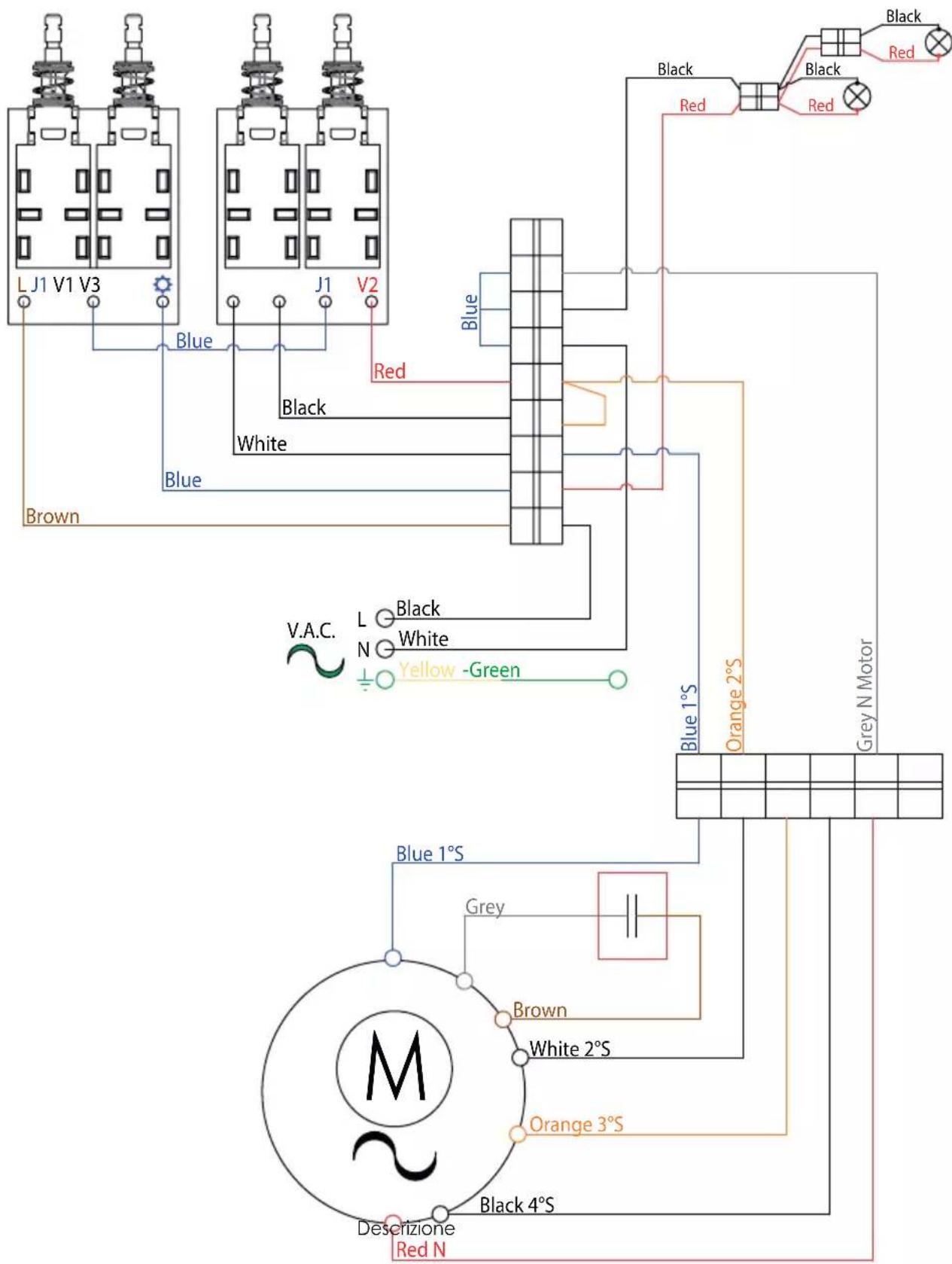
text_image
L J1 V1 V3 J1 V2 Blue Black White Brown V.A.C. L Black N White Yellow -Green Blue 1°S Orange 2°S Grey N Motor Blue 1°S Grey Brown White 2°S Orange 3°S Descrizione Red N Black 4°SWiring Diagram
For Models ZVA-E30AS, ZVA-M90AS
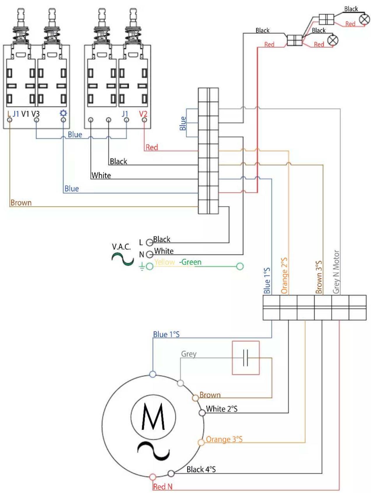
text_image
L J1 V1 V3 Blue Black White Brown V.A.C. L Black N White Yellow -Green Red Blue Black Red Black Red Blue 1°S Orange 2°S Brown 3°S Grey N Motor Blue 1°S Grey Brown White 2°S Orange 3°S Black 4°S Red NList of Parts and Accessories
| DESCRIPTION HOOD PART# | ||
| REPLACEMENT PARTS | ||
| LED Light 1.3W (each) | ZVA | Z0B0056 |
| OPTIONAL ACCESSORIES | ||
| Recirculating Kit | ZVA | ZRC-00VA |
| Replacement Charcoal Filters (2x) | ZVA | Z0F-C011 |
| Lower mesh filter (ZVA-M90AS - ZVA-M90AS290) | ZVA | 50200074 |
| Upper mesh filter (ZVA-M90AS - ZVA-M90AS290) | ZVA | 50200075 |
| Lower mesh filter (ZVA-E30AS - ZVA-E30AS290) | ZVA | 50200072 |
| Upper mesh filter (ZVA-E30AS - ZVA-E30AS290) | ZVA | 50200073 |
| Lower mesh filter (ZVA-M60AS290) | ZVA | |
| Upper mesh filter (ZVA-M60AS290) | ZVA |
To order parts, visit us online at http://store.zephyronline.com
| UL References | |
| LED Light 1.3W (each) SPK8148 | |
| Recirculating Kit KIT0I0628 | |
| Replacement Charcoal Filters ACK00261 | |
| Lower mesh filter (ZVA-M90AS - ZVA-M90AS290) SPK9509 | |
| Upper mesh filter (ZVA-M90AS - ZVA-M90AS290) SPK9510 | |
| Lower mesh filter (ZVA-E30AS - ZVA-E30AS290) SPK9516 | |
| Upper mesh filter (ZVA-E30AS - ZVA-E30AS290) SPK9517 | |
| Lower mesh filter (ZVA-M60AS290) SPK9562 | |
| Upper mesh filter (ZVA-M60AS290) SPK9561 | |
ZEPHYR Limited Warranty
TO OBTAIN SERVICE UNDER WARRANTY OR FOR ANY SERVICE RELATED QUESTIONS: United States Customers please call: 1-888-880-8368 or contact us at: zephyronline.com/contact Canada Customers please call: 1-800-361-0799 or Email: service@distinctive-online.com
Zephyr Ventilation, LLC (referred to herein as "we" or "us") warrants to the original consumer purchaser (referred to herein as "you" or "your") of Zephyr products (the "Products") that such Products will be free from defects in materials or workmanship as follows:
Two Year Limited Warranty for Parts: For two years from the date of your original purchase of the Products, we will provide, free of charge, Products or parts (including LED light bulbs, if applicable) to replace those that failed due to manufacturing defects subject to the exclusions and limitations below. We may choose, in our sole discretion, to repair or replace parts before we elect to replace the Products.
One Year Limited Warranty for Labor: For one year from the date of your original purchase of the Products, we will provide, free of charge, the labor cost associated with repairing the Products or parts to replace those that failed due to manufacturing defects subject to the exclusions and limitations below. After the first year from the date of your original purchase, you are responsible for all labor costs associated with this warranty.
Warranty Exclusions: This warranty covers only repair or replacement, at our option, of defective Products or parts and does not cover any other costs related to the Products including but not limited to: (a) normal maintenance and service required for the Products and consumable parts such as fluorescent, incandescent or halogen light bulbs, mesh and charcoal filters and fuses; (b) any Products or parts which have been subject to freight damage, misuse, negligence, accident, faulty installation or installation contrary to recommended installation instructions, improper maintenance or repair (other than by us); (c) commercial or government use of the Products or use otherwise inconsistent with its intended purpose; (d) natural wear of the finish of the Products or wear caused by improper maintenance, use of corrosive and abrasive cleaning products, pads, and oven cleaner products; (e) chips, dents or cracks caused by abuse or misuse of the Products; (f) service trips to your home to teach you how to use the Products; (g) damage to the Products caused by accident, fire, floods, acts of God; or (h) Custom installations or alterations that impact serviceability of the Products. If you are outside our service area, additional charges may apply for shipping costs for warranty repair at our designated service locations and for the travel cost to have a service technician come to your home to repair, remove or reinstall the Products. After the first year from the date of your original purchase, you are also responsible for all labor costs associated with this warranty. All Products must be installed by a qualified professional installer to be eligible for warranty repairs or service.
Limitations of Warranty. OUR OBLIGATION TO REPAIR OR REPLACE, AT OUR OPTION, SHALL BE YOUR SOLE AND EXCLUSIVE REMEDY UNDER THIS WARRANTY. WE SHALL NOT BE LIABLE FOR INCIDENTAL, CONSEQUENTIAL OR SPECIAL DAMAGES ARISING OUT OF OR IN CONNECTION WITH THE USE OR PERFORMANCE OF THE PRODUCTS. THE EXPRESS WARRANTIES IN THE PRECEDING SECTION ARE EXCLUSIVE AND IN LIEU OF ALL OTHER EXPRESS WARRANTIES. WE HEREBY DISCLAIM AND EXCLUDE ALL OTHER EXPRESS WARRANTIES FOR THE PRODUCTS, AND DISCLAIM AND EXCLUDE ALL WARRANTIES IMPLIED BY LAW, INCLUDING THOSE OF MERCHANTABILITY AND FITNESS FOR A PARTICULAR PURPOSE.
Some states or provinces do not allow limitations on the duration of an implied warranty or the exclusion or limitation of incidental or consequential damages, so the above limitations or exclusions may not apply to you. To the extent that applicable law prohibits the exclusion of implied warranties, the duration of any applicable implied warranty is limited to the same two-year and one-year periods described above if permitted by applicable law. Any oral or written description of the Products is for the sole purpose of identifying the Products and shall not be construed as an express warranty. Prior to using, implementing or permitting use of the Products, you shall determine the suitability of the Products for the intended use, and you shall assume all risk and liability whatsoever in connection with such determination. We reserve the right to use functionally equivalent refurbished or reconditioned parts or Products as warranty replacements or as part of warranty service. This warranty is not transferable from the original purchaser and only applies to the consumer residence where the Product was originally installed located in the United States and Canada. This warranty is not extended to resellers.
To Obtain Service Under Limited Warranty: To qualify for warranty service, you must: (a) notify us at the address or telephone number stated below within 60 days of the discovery of the defect; (b) give the model number and serial number; and (c) describe the nature of any defect in the Product or part. At the time of the request for warranty service, you must present evidence of your proof of purchase and proof of the original purchase date. If we determine that the warranty exclusions listed above apply or if you fail to provide the necessary documentation to obtain service, you will be responsible for all shipping, travel, labor and other costs related to the services. This warranty is not extended or restarted upon warranty repair or replacements.
Please check our website for any additional Product information, www.zephyronline.com.
Zephyr, 2277 Harbor Bay Parkway, Alameda, CA 94502
VALINA
ZVA-M60AS290
ZVA-E30AS290
ZVA-M90AS290
ZVA-E30AS
ZVA-M90AS
natural_image
Technical line drawing of a rectangular enclosure with a circular top and mounting holes (no text or symbols)
Instructions De Securite 2/5
* National Fire Protection Association Batterymarch Park, Quincy, Massachusetts 02269
** CSA International 8501 East Pleasant Valley Road, Cleveland, Ohio 44131-5575
Instructions De Securite 5/5
Instructions De Securite 6/6
Specifications Techniques
text_image
= 19-3/4" (24") - 26-1/8" (30") - 31-9/16" (36") 5-7/8" 1-1/8" 12-1/8" 1-5/8" 9" Min 0-3/8" - Max 1-3/16"text_image
3-13/16" 0 - 5-7/8"text_image
0-1/2" 0-1/2" 11-1/16" Min 12" - Max 17-7/8" 0-15/16" 23-9/16" (24") - 29-15/16" (30") - 35-3/8" (36") 1-1/4" 0-7/16" 5-1/8" 2-1/2" 0-7/16" 8-9/16"Fig.1
Installation
text_image
11-3/16" 19-7/8" (24") 26-1/4" (30") 31-11/16" (36")Fig.2
text_image
Diagram illustrating airflow or ventilation process with labeled steps 1 and 2, showing directional arrows and hand positioning.Fig.3
Installation
text_image
1 24" - 36" - 30" A 3 4 B 2 2 1 2 Min 0-3/8" Max 1-3/16" F M FFig.4
1. FIXATION DE LA HOTTE À LA TABLETTE DU BAS DES ARMOIRES:
text_image
3 Y D X L C A Y X 3.1 L C 3.2 3.3 3.2 3.3 4 D D P L P 5Fig.4
Installation
2. FIXATION DE LA HOTTE À UNE TABLETTE DE L'INTÉRIEUR DES ARMOIRES.
text_image
30" 4 E G E 5Fig.6
3. POUR LES HOTTES DE 30 PO SEULEMENT – FIXATION DE LA HOTTE DANS LE BAS DES ARMOIRES À L'AIDE DES ÉTRIERS DE MONTAGE.
text_image
Technical diagram showing four steps of a mechanical assembly or repair procedure, labeled 1 to 4 with numbered components and directional arrows.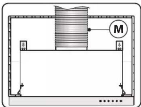
natural_image
Diagram of a mechanical setup with a cylindrical component and labeled mass M, no text or symbols presentContrôle
text_image
Technical diagram showing a mechanical assembly with labeled components and directional arrows indicating movement or force.Zephyr, 2277 Harbor Bay Parkway, Alameda, CA 94502
JAN21.0201
PRODUCT REGISTRATION
Congratulations on your Zephyr range hood purchase! Please take a moment to register your new range hood at www.zephyronline.com/registration
IT'S IMPORTANT
Prompt registration helps in more ways than one.
- Ensures warranty coverage should you need service.
- Ownership verification for insurance purposes.
- Notification of product changes or recalls.

text_image
STOPZephyr Ventilation | 2277 Harbor Bay Pkwy. | Alameda, CA 94502 | 1.888.880.8368