INV600N - Electrical Transformer Pro-User - Free user manual and instructions
Find the device manual for free INV600N Pro-User in PDF.


User questions about INV600N Pro-User
0 question about this device. Answer the ones you know or ask your own.
Ask a new question about this device
Download the instructions for your Electrical Transformer in PDF format for free! Find your manual INV600N - Pro-User and take your electronic device back in hand. On this page are published all the documents necessary for the use of your device. INV600N by Pro-User.
USER MANUAL INV600N Pro-User
Please read this instruction manual carefully before installing and starting up the device, and store it in a safe place. If the device is passed on to another person, this manual must also be handed over with it.
Contents
- Notes on using the manual. 4
- Safety instructions 4
- Device guides 6
- Technical description.. 7
- Connecting the inverter 8
- Using the inverter 10
- Replacing the fuse. 12
- Cleaning and caring for the inverter 12
- Troubleshooting 13
10.Guarantee. 14
11.Disposal. 14 - Technical date 15
1 Notes on using the manual

Caution
Safety instruction: Failure to observe this instruction can cause material damage and impair the function of the device.

Caution
Safety instruction: relating to a danger from an electrical current or voltage. Failure to observe this instruction can cause material damage and personal injury and impair the function of the device.

Note
Supplementary information on operating the device

Action: This symbol indicates that action is required on your part. The required action is described step-by-step.

This symbol describes the result of an action.
Please observe the following safety instructions.
2 Safety instructions
2.1 General safety

Caution
The manufacturer will not be held liable for claims for damage resulting from the following:
— Faulty assembly or connection
- Damage to the appliance resulting from mechanical influences and excess voltage
- Alterations to the device without express permission from the manufacturer
Use for purposes other than those described I the operating manual
- Use the device only as intended.
- Do not operate the device in a damp or wet environment.
- Maintenance and repair work may only be carried out by qualified personnel who are familiar with the risk involved and the relevant regulations.
2.2 Safety when installing the device
- Ensure the device is standing firmly.
The device must be set up and fastened in such a way that it cannot tip over or fall down. - Take the precautions necessary to ensure that children cannot interfere with operation.
Dangerous situations may occur which cannot be recognized by children! - Do not expose the device to a heat source (such as direct sunlight or heating). Avoid additional heating of the device in this way.
For installation on boats
- If electrical devices are incorrectly installed on boats, corrosion damage might occur. Have the inverter installed by a specialist (marine) electrician.
Electrical cables
- If cables have to be fed through metal walls or other walls with sharp edges, use ducts or wire bushings to prevent damage.
- Do not lay cables which are loose or bent next to electrically conductive material (metal).
- Do not pull on the cables.
- Do not lay the 230 V mains cable and the 12 V DC cable in the same duct.
- Fasten the cables securely.
- Lay the cables so that they cannot be tripped over or damaged.
2.3 Operating the appliance safely
Caution
Note the following basic safety information when using electrical devices to protect against:
— Electric shock
Fire hazards
Injury
- Do not operate the advice near gas or flammable material; the surface temperature can reach up to 65^ .
- Operate the device only if you are certain that the housing and the cables are undamaged.
- Make sure the air inlets and outlets of the device are not covered.
- Ensure good ventilation.
- Do not connect the 230V output of the inverter (fig. 1.2, page 2) to a different 230V source.
- Even after the fuse triggers, parts of the inverter remain live.
- Always disconnect the power supply when working on the device.
3 Device guides
Description
Item No.
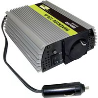
Modified sine wave INC150N: inverter in cup shape with USB socket and cable for 12V socket. INC150N
Modified sine wave INV150N: inverter with USB socket, and cable for 12V socket. INV150N
Modified sine wave INV300N: inverter with USB socket, and one cable for 12V socket, and two cables for 12V battery. INV300N
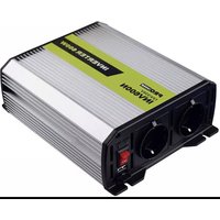
Modified sine wave INV600N: inverter with USB socket, and one cable for 12V socket, and two cables for 12V battery. INV600N
Modified sine wave INV1000N: inverter with USB socket, and two cables for 12V battery. INV1000N
Modified sine wave INV1500N: inverter with USB socket, and two cables for 12V battery. INV1500N
Modified sine wave INV2000N: inverter with USB socket and two cables for 12V battery. INV2000N
4 Technical description
The inverters are used to convert a direct current of 12V into a 230V AC supply of 50 HZ, and/or 5V 2100mA USB.
The inverter can be operated wherever there is a 12V DC supply. The devices are additionally cooled with a load fan.
The maximum constant output for the devices is as follows:
- For INC150N and INV150N inverters 150W
For INV300N inverter 300W
For INV600N inverter 600W
For INV1000N inverter 1000W
For INV1500N inverter 1500W
For INV2000N inverter 2000W
Never connect devices that have a higher power requirement.
The inverter is equipped with protection against thermal and electrical over-loading, as well as excess and insufficient voltage. The inverter alarms and switches off:
- if its internal temperature is too high
- if the load exceeds the values stated above
- if the input voltage is too high or too low
The inverter can be switched on and off using the switch directly on the device.

Note
Note when connecting devices with an electrical drive (such as power drills and refrigerators), that they often require more power than the data is indicated on the type plate.
5 Connecting the inverter
5.1 Fastening the inverter
You can fasten the inverters (INV300N, INV600N, INV100N0, INV1500N and INV2000N) by screwing through the holes on the underside.
When selecting the installation location, observe the following instructions:
- The inverter can be mounted horizontally or vertically.
- The inverter must be installed in a place that is protected from moisture.
- The inverter may not be installed in the presence of flammable materials.
The inverter may not be installed in a dusty environment. - The place of installation must be well-ventilated. A ventilation system must be present for installations in small, closed spaces. The minimum clearance around the inverter must be at least 25~cm .
- The air intake on the front side or the air outlet on the back of the inverter must remain clear.
- For ambient temperatures higher than 40^ (such as in engine or heating compartments, or direct sunlight). The heat from the inverter under load can lead to the automatic shut-off of the inverter.
- The installation surface must be level and sufficiently sturdy.

Caution
Before drilling any holes, ensure that no electrical cables or other parts of the vehicle can be damaged by drilling, sawing and filing.
5.2 Connecting the inverter with car socket (INC150N, INV150N, INV300N and INV600N)
The inverter is connected via a plug connected to a 12V socket. The middle pin of the plug must be connected to the position wire and the two side brackets of the plug must be connected to the negative wire.

Caution
Make sure the plug is firmly connected in the socket. If the connection is loose, the plug may heat up.
Caution
The rating of the socket, the supply cable and the fuse must be at most 15amps. Do not put in a fuse with a higher rating.
Caution
Always check the rated power of device before connecting with car socket. Its rated power can NOT be more than 100W.
5.3 Connecting the inverter with battery (INV300N, INV600N, INV1000N, INV1500N and INV2000N)
To set up the inverter, connect the red cable to the positive pole (+) of the battery and inverter, connect the black cable to the negative pole (-) of the battery and inverter.

Caution
Make sure the battery poles are clean when connecting the terminals.
Tighten the nuts and bolts to a torque of 12-13 Nm. Loose connections may cause overheating.
Caution
Do not reverse the polarity. Reversing the polarity of the connections will cause a great spark and the internal fuses will melt.

Caution
Only extend the connection line with cables with and equal or greater cross section.
Below cross section is for 100% copper wire, does not include thickness of wire cover.
| Device | Required cable cross section | Cable standard in AWG |
| 100% copper wire (American wire gauge) | ||
| INV300N | 3.00mm² | 14#AWG |
| INV600N 5.30mm² | 10#AWG | |
| INV1000N 10.00mm² | 8#AWG | |
| INV1500N 16.00mm² | 5#AWG | |
| INV2000N 2x12.00mm² | 2x7#AWG | |
6 Using the inverter
Switch on at the device

Set the main switch(fig. 1.4 page 2) to "ON".

The green LED (fig. 1.5 page 2) lights up.
Switch off at the device

Set the main switch(fig. 1.4 page 2) to "OFF".

The green LED (fig. 1.5 page 2) goes out.
Observe the following when using the device
If the battery voltage falls below 11V during operation, a warning tone sounds. If the battery voltage falls further, the inverter switches off and the red error LED (fig. 1.5 page 2) lights up.
If the inverter overheats, it switches off - the red error LED lights up.

If this happens, switch the inverter off with the switch.
When it cools down, you can use the inverter again.
When operating the inverter at a high load for lengthy periods, it is advisable to start the engine in order to recharge the vehicle battery.
You can operate the inverter with the engine running or switched off.
However, do not start the engine while the inverter is switched on, since the power supply to the cigarette lighters is disconnected during ignition.

Caution
Modified sine wave inverter could operate with most electrical device. Please check with the manufacturer of the product you are going to use if it is possible. For example there might be problems operating with precise instrument, e.g. high precision research testing equipment, medical monitor.
USB port
Connect the USB external appliance to the USB port and switch it on. The USB port on the power inverter provides a power supply of 5V DC for external USB devices.
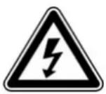
Warning
The USB port on the power inverter is not designed for transferring data. Do not connect memory sticks, MP3 player or similar data storage external appliances. Do not connect any data transfer cable to the USB port.
7 Replacing the fuse
This is how to change the fuse of the inverter
Take the defective fuse (fig. 2.7 page 2) out of the holder on the back.
Put in a new fuse of the same rating.

Note
For item INC150N, INV150N, INV300N, INV600N, always check the fuse in cigarette plug first.
For item INV1000N, INV1500N, INV2000N, its fuse is inside of inverter.
Unscrew the 4 screws (fig. 2.9 page 2) to replace the fuses.
8 Cleaning and caring for the inverter

Caution
Do not use sharp or hard objects or cleaning agents for cleaning as these may damage the device
Occasionally clean the device with a damp cloth.
9 Troubleshooting
| Fault | Cause | Remedy |
| No output voltage | No contact to the battery | Check contact and cable. Switch On the ignition if necessary.INC150N/ INV150N/ INV300N/ INV600N: check the 12V socket and replace it if necessary. |
| Overheating Switch off power | er consuming devicesLet the inverter cool down and ensure better ventilation. | |
| Defective fuse (in the Cigarette plug, inverter, or The vehicle) | Replacing the fuse with one of the same specification. | |
| Device defective | Replace the device. | |
| Interference | From TV set systems and / or other external appliances operation snow image, image not steady humming, booming and whirring sound audible. | aRtioe power inverter as far away from TV set as possible, check aerial connection and setting. Place aerial cable away from power inverter. Use a shielded aerial cable. The modified sine wave of the power inverter cannot be filtered sufficiently by the connected external appliance. disconnect all cables immediately. The only available solution is to use a more modern external appliance or one with a higher rating with adequate filtering capability. |
| The device switches On and off repeatedly | Excessive constant load Reduce the load. | |
10 Guarantee
The statutory warranty period applied. If the product is defective, please discuss further steps with the dealer where you have bought the device
11 Disposal

If possible, always take the packing material for recycling.
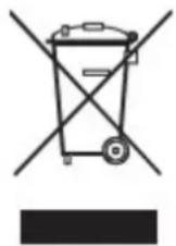
If you wish to finally dispose of the device, ask your local recycling center or specialist dealer for details about how to do this in accordance with the applicable disposal regulations.
12 Technical data
| Item no: | INC150N | INV150N | INV300N | INV600N | INV1000N | INV1500N | INV2000N |
| Output power: | 150W | 150W | 300W | 600W | 1000W | 1500W | 2000W |
| Fuse in cigarette plug | 15Ax1 | 15Ax1 | 15Ax1 | 15Ax1 | -- | -- | -- |
| Spade-type fuse | 25Ax1 | -- | 20Ax2 | 20Ax4 | 20Ax6 | 30Ax6 | 25Ax10 |
| Wave form | Modified Sine wave | ||||||
| Rated input voltage | DC 12V | ||||||
| Input voltage range | 11V - 15V | ||||||
| output AC | 230V +/- 10% | ||||||
| output frequency range | 50 +/- 2 HZ | ||||||
| USB output | 5V 2100mA | ||||||
| Ambient temperature for operation | 0°C - 40°C | ||||||
| Ambient temperature for storage | -30°C - 70°C | ||||||
| Efficiency up to | 90% | ||||||
| High voltage shutdown | Shutdown: 15-16v | ||||||
| Low voltage shutdown | warning: 10.5-11.0V | ||||||
| shutdown: 10V-11VAutomatic restart: 12V +/- 1V | |||||||
| High temperature shutdown | Internal temperatureShutdown at 70°C+-5°CCooling elementShutdown at 90°C | ||||||
Kabelstandard in AWG
EU – Declaration of Conformity
We herewith confirm that the appliance as detailed below complies with the mentioned directives.
Article name (Model name)
Firmenanschrift (Company address)
19117, 19118, 19119, 19120, 19121, 19122, 19123
INC150N, INV150N, INV300N, INV600N, INV1000N, INV1500N, INV2000N
Pro-User Europe GmbH, Seestasse 19, 83253 Rimsting, Germany
Einschlagige EG-Richtlinien / governing EU-directives / directives CE concennces:

Electromagnetic compatibility (EMC)
2004/108/EC
Low voltage directive (LVD)
2006/95/EC

- Funkanlagen und
Radio and Telecommunication Terminal Equipment
R&TTE 1999/5/EC

- ROHS
2011/65/EC (method EN62321)
The article complies with the standards as mentioned below which are necessary to obtain the CE-symbol:
Zu 1.
EN50498:2010
Zu 2.
EN60950-1: 2006 +A11:2009+A1:2010+A12:2011
Appliance only for use in cars