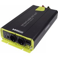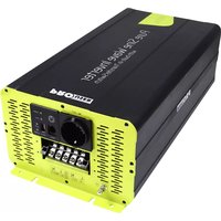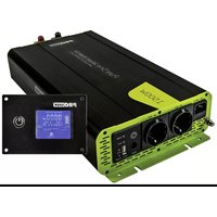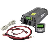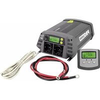
PSI600 - Electric converter Pro-User - Free user manual and instructions
Find the device manual for free PSI600 Pro-User in PDF.


User questions about PSI600 Pro-User
0 question about this device. Answer the ones you know or ask your own.
Ask a new question about this device
Download the instructions for your Electric converter in PDF format for free! Find your manual PSI600 - Pro-User and take your electronic device back in hand. On this page are published all the documents necessary for the use of your device. PSI600 by Pro-User.
USER MANUAL PSI600 Pro-User
The PURE SINEWAVE INVERTERS are a member of the family of advanced mobile power inverters manufactured by Pro-User. Your Pro-User PURE SINEWAVE INVERTER enables you to generate a pure sine wave 230V 50Hz voltage from a 12V DC battery wherever your travels take you. As a bonus we built-in 2 USB-Ports for powering or charging e.g. your sat nav, cell phone, tablet or any other USB device. Because of the high quality pure sine wave voltage and the excellent overload capabilities, even sensitive electronics will work flawlessly.
The wired remote control enables you to monitor and control your inverter in a convenient way. With the built-in solar charge controller (only PSI1000 & PSI1500) you even can directly connect PV solar panels up to 500W to the inverter to recharge your battery.
We have taken numerous measures in quality control to ensure that your product arrives in top condition and will perform to your satisfaction.
Please carefully read and follow the safety and operating instructions. Not following these instructions may result in a serious accident, including damaged property, serious or even fatal injuries. If the device is passed on to another person, this manual must also be handed over with it.
IMPORTANT SAFETY INSTRUCTIONS

CAUTION: Please read this instruction manual carefully before installing and starting up the device. Do not operate the inverter unless you have fully read and understood all the provided information. If you are not confident working with 12V DC voltage or are unsure of what you are doing, consider to seek for help by a professional installation service or your vehicle's manufacturer. Failure to observe these instructions may cause an electrical shock, fatal or serious injury, material damage or impair the function of the inverter.
Pro-User accepts no liability for direct or indirect damage caused by faulty assembly or connection, a usage of damaged or altered products, a usage for purposes other than described and especially caused by failure to follow these instructions.
General:
• Electrical devices are not toys. Keep the product away from children.
- Only use the product as intended and for purposes described in the manual.
- After opening the package, examine all parts for visible damage. If you have found any damage, please contact the company you purchased this unit from.
- Always disconnect the power supply (including the connection to the battery and an optional solar panel) when working on the device.
- Use only approved accessories (especially all cables) or parts fully consistent with the requirements. The installer is responsible for ensuring that the correct cable and fuse sizes are used.
- The surface temperature can reach up to 65^ C. Power-off and stop using the device immediately, if the unit is smoking or is showing any abnormal behaviour.
- This appliance is not intended for use by persons (including children) with reduced physical, sensory or mental capabilities, or lack of experience and knowledge, unless they are supervised or have been instructed on how to use the appliance by a person responsible for their safety. Children should be supervised to ensure that they do not play with the appliance.
- Installing the device, maintenance and repair work may only be carried out by qualified personnel who are familiar with the risks involved, the relevant regulations and with the guidelines and safety precautions to be applied.
- Do not disassemble the inverter - the internal circuitry contains hazardous voltages. Attempting to service the unit yourself may result in electric shock or fire and will void the unit warranty.
- Always keep metal objects or other materials that can short circuit the terminals of the battery or the inverter securely away. A resulting spark or short-circuit may not only damage the device, but also cause an explosion and potentially produce a current high enough to weld a ring or the like to metal. Remove personal metal items such as rings, bracelets, necklaces, and watches when working on the device or the battery.
- Operate the inverter only, if all cables and the housing are undamaged and all connections are tight and clean. Loose or dirty connections could result in overheating, electrical sparks and fire.
- Do not connect AC output terminals of the inverter to an incoming AC source (or the grid).
- Do not connect DC input terminals of the inverter to an incoming AC source.
- Never use the inverter on vehicles where the positive terminal of the battery is connected to the chassis.
- Never connect cables in reverse polarity or short-circuit connected cables. This may blow internal fuses and may damage the inverter permanently.
- A fuse should be provided at a distance of max. 30 cm from the battery's positive terminal. Failure to do so, may cause damage to the cabling or battery if a fault (e.g. over-current or short circuit) occurs. Only use high quality copper cable and keep the cable length short.
- Do not operate appliances that may feed AC main power back into the inverter. This might damage the inverter.
- Ensure the device is standing firmly. The device must be set up and fastened in such a way that it cannot tip over or fall down.
- Never connect devices that have a higher power requirement than the peak output power of the inverter. Note that some devices may require more starting current than the type plate of the device indicates.
Working with Batteries
- Batteries can store large amounts of energy and improper handling can be dangerous. NEVER CONNECT to a battery with an unsuited voltage or other unsuitable or damaged batteries
- Keep children away from batteries and acid.
- Avoid getting electrolyte on your skin or clothes. It is acidic and can cause burns. If battery acid contacts skin or clothing, wash immediately with water. Baking soda neutralizes lead acid battery electrolyte. If electrolyte gets into your eyes, immediately flood your eyes with running cold water for at least 20 minutes and get medical attention immediately. Eye protection is therefore recommended.
- Always keep metal objects or other materials that can short circuit the terminals of the battery or the inverter securely away.
• Power-off the device before making or breaking the connections to the battery. - Depending on the type of battery, when the battery is being charged (by an optionally connected solar panel - only PSI1000 & PSI1500), you may notice bubbling in the fluid caused by the release of gas. As the gas is flammable, avoid naked flames, glowing or electrostatically charged material and sparks in the vicinity of the battery. Always provide adequate ventilation. Make sure the inverter is not in direct vicinity of the battery.
- Observe technical instructions of the seller or the manufacturer of your battery
- Check if all connections are tight and clean. Loose or dirty connections could result in overheating, electrical sparks and fire. Use terminal grease where required.
- Never smoke or allow a spark or flame in vicinity of the battery.
- Never try to charge a damaged or frozen battery.
- Do not place the device directly on top of the battery or vice versa or on a surface constructed from combustible material.
- Read your car's owner's manual. Some vehicle manufacturers may have special requirements before charging or discharging the vehicle's battery (e.g. fuses that have to be removed or certain security demands).
Environment:
- Only use the product in environments from -20^ 50^ .
- Do not operate the product in damp, wet or dusty environments: Never expose the inverter to rain or snow. Doing so may result in damage to the inverter or other equipment installed in the system or result in electric shock or fire. Do not operate the unit in explosive atmospheres, such as in the presence of flammable liquids, gases or dust. Do not put batteries, or anything that should be protected from sparks around the inverter. Doing so may result in fire or explosion.
- To avoid heat accumulation, do not cover the device. To prevent overheating, ensure that air inlets and ventilation is not obstructed. Do not expose the device to a heat source (such as direct sunlight or heating). Avoid additional heating of the device in this way.
Electrical Cables
- If cables have to be fed through metal holes or other walls with sharp edges, use ducts or cable bushings to prevent damage.
- Do not lay cables which are loose or bent next to electrically conductive material (metal).
- Do not pull on the cables.
- Avoid to lay 230 V mains cable and 12 V DC cables in the same duct.
- Prevent all cables from being stepped on, tripped over, or being damaged by e.g. sharp edges or hot surfaces.
GENERAL INSTRUCTIONS
Intended use
The PRO-USER SINE WAVE INVERTER converts a 12V direct current voltage (e.g. a battery or another 12V source that can deliver the required current) into 200-240V 50Hz AC pure sine wave voltage. The built-in USB-Ports are intended to power or charge 5V USB devices (the maximum current delivery has to be kept in mind). The wired remote control enables the user to monitor and control the inverter in a convenient way.
Only PSI1000 & PSI1500: With the built-in solar charge controller, connected PV panels up to 500W (but max. 30A and 16-45V) can recharge a connected lead-acid battery.
Maintenance
The unit itself is maintenance-free. From time to time, make sure all cable connections are clean and tight and fans are working correctly. If necessary, clean the unit with care, using a dry cloth. Don't try to open the body casing. There are no user-serviceable parts inside. Damage due to improper use, modifications or attempted repairs lead to the exclusion of liability and the loss of warranty. If the unit is damaged, the appliance must be discarded. Cleaning and user maintenance shall not be made by children.
Packaging materials
To avoid danger of suffocation, do not let children play with foils or other packaging materials. Remove all protective coverings before putting the device in operation.
Storage
When not in use, store the inverter in a dry environment. Store the device in a safe place out of the reach of children. Protect the unit from direct sunlight, heat and moisture.
SCOPE OF DELIVERY
• Pro-User Pure Sine Wave Inverter
- Wired remote control unit with connection cable
- Operating manual
Front panel of the inverter:
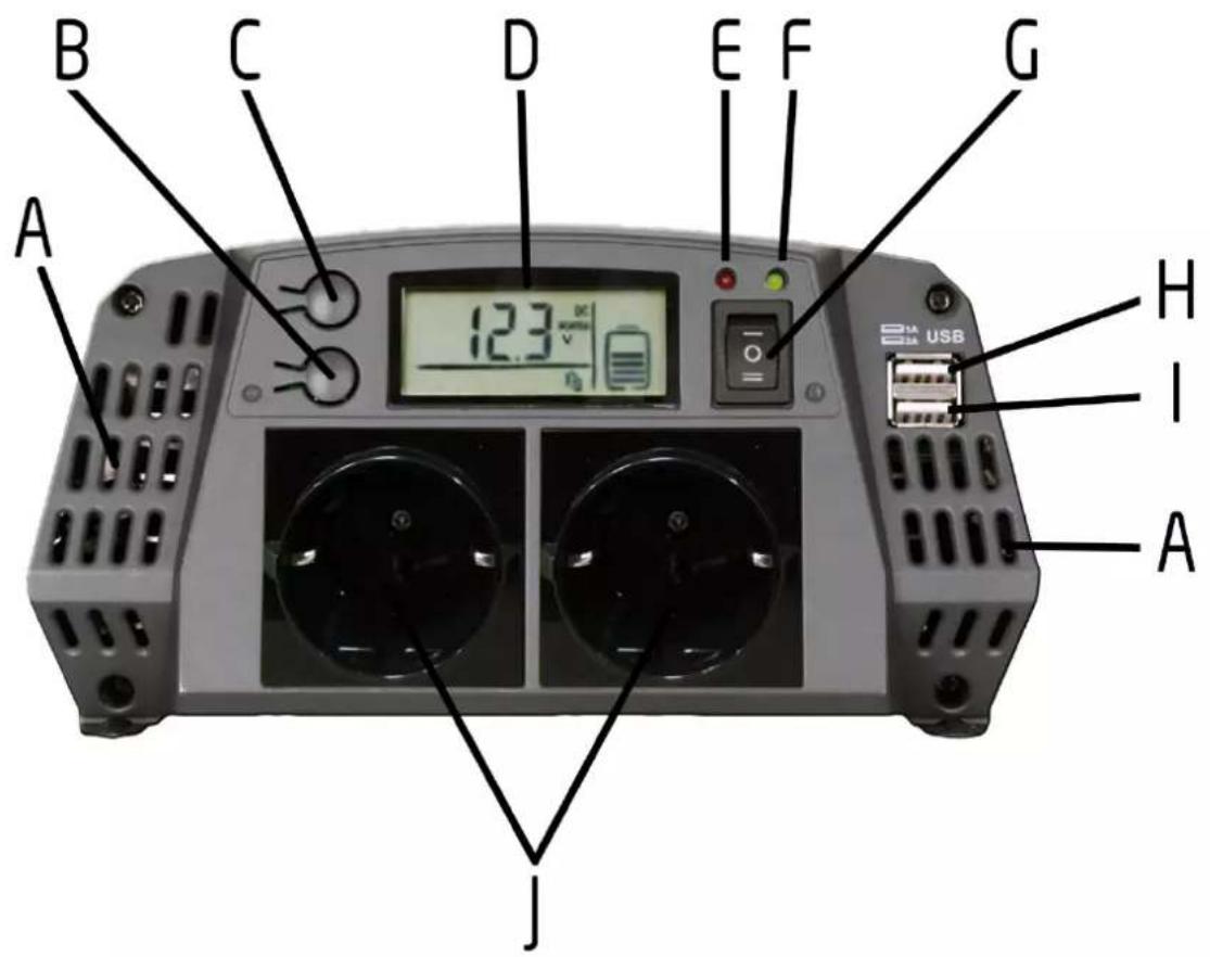
text_image
B C D E F G A 12.3 V/Ω USB H I A J| Item | Description |
| A | Air-Inlets: Do not cover ! |
| B | MODE-Button: Press the button to toggle the displayed measured values |
| C | BACKLIGHT-Button:- Press this button briefly to turn on the LCD-backlight for 1 minute - press again to turn the LCD-backlight off- Press and hold this button for 3 seconds to activate the SLEEP-Mode |
| D | LCD-Display: shows all the relevant information such as voltage, current, wattage, etc. |
| E | Red LED: Signal-lamp that indicates errors and alarms |
| F | Green LED: Signal-lamp that indicates readiness for operation |
| G | Main-Switch: Switches between the operation modes of the inverter: on/off/remoteSwitch-Position 0: Standby-Mode: Inverter-function is OFF (no output on the 230V sockets available, LCD is OFF), 5V-USB-output is ON, Charge-Function is ON if PV solar panels are connected (the LCD will light up and charge a connected battery)Switch-Position I: Remote-control-function is OFF, Inverter-function is ON (230V is available on the sockets), 5V-USB-output is ON, Charge-function is ON if PV solar panels are connectedSwitch-Position II: Remote-control-function is ON, Inverter-function is ON (230V is available on the sockets), 5V-USB-output is ON, Charge-function is ON if PV solar panels are connected |
| H | USB power supply: delivers 1A of current to power or charge 5V USB devices |
| I | USB power supply: delivers 2A of current to power or charge 5V USB devicesIf the requested USB output power exceeds 3A, USB overcurrent protection will be activated and the USB output will turn off. USB output will resume after 5 sec.If the battery voltage is lower than 10.5V, USB output is turned off, but will resume automatically when battery voltage rises over 12V again. |
| J | 230 V socket: delivers a 230V 50Hz pure sine wave output (Switch-position I and II ).The output can deliver up to 600W (PSI600) / 1000W (PSI1000) / 1500W (PSI1500) of continuous power.For a short period (max. 20 min) it can deliver an overload power up to 660W (PSI600) / 1100W (PSI1000) / 1650W (PSI1500).Peak power is up to 1200W (PSI600) / 2000W (PSI1000) / 300W (PSI1500) for max. 1 sec.If the battery’s voltage is lower than 10.5V, undervoltage-protection is activatedNOTE: Use the outputs separately and never connect them to the grid. |
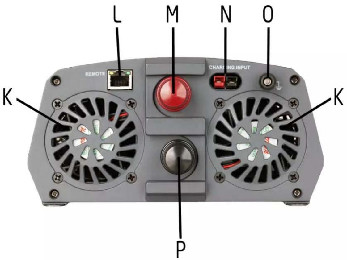
text_image
L M N O CHARGING INPUT REMOTE K P K| Item | Description |
| K | Fan: Do not cover the vent holes! |
| L | Remote-Connector: Connect the wired remote control to this port |
| M | + Positive battery terminal (red): Connect the positive pole of the battery to this terminal |
| N | Only present at models PSI1000 & PSI1500:Charging-Input for PV solar panels:Input voltage: 16-45V DCInput current/ power: max. 30A PWM (max. 500W)Output charging voltage: 7V DC - 14.4V DCObserve polarity:red-clamp: terminal for positive cable of the input voltageblack-clamp: terminal for negative cable of the input voltageIf polarity is accidentally reversed, the inverter will indicate an error.NOTE: Only charge rechargeable lead-acid batteries. Please read the safety instructions carefully before working with batteries. |
| O | Grounding terminal - Connect to ground |
| P | - Negative battery terminal (black): Connect the negative pole of the battery to this terminal |
Remote unit of the inverter (only at main switch position II)
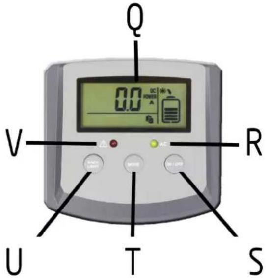
text_image
Q 0.0 POWER A V R U T S| Item | Description |
| Q | LCD-Display: shows all the relevant information such as voltage, current, wattage, etc. |
| R | Green LED: Signal-lamp that indicates readiness for operation |
| S | ON/OFF-Button: Press to turn the inverter-function on or off.OFF: Standby-Mode: Inverter-function is OFF (no output on the 230V sockets available, LCD is OFF), 5V-USB-output is ON, Charge-Function is ON if PV solar panels are connected (the LCD will light up and charge a connected battery)ON: Inverter-function is ON (230V is available on the sockets), 5V-USB-output is ON, Charge-function is ON if PV solar panels are connected |
| T | MODE-Button: Press the button to toggle the displayed measured values |
| U | BACKLIGHT-Button:- Press this button briefly to turn on the LCD-backlight for 1 minute - press again to turn the LCD-backlight off- Press and hold this button for 3 seconds will activate the SLEEP-Mode |
| V | Red LED: Signal-lamp that indicates errors and alarms |
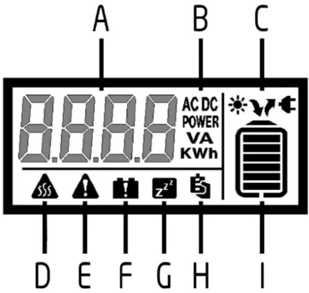
text_image
A B C 8.8.8 AC DC POWER VA KWh 555 ! ! z²² D E F G H I| Item | Description |
| A | LCD-Display: shows all the relevant information such as voltage, current, wattage, etc. |
| B | Displays the unit of the currently measured value. Press the button to toggle the displayed measured values |
| C | Only at models PSI1000 & PSI1500: If a PV solar panel and a battery is connected, an arrow under the sun symbol will flash that indicates the battery charging process. |
| D | Over temperature protection: When this icon appears and flashes, the inverter automatically enabled over temperature protection. |
| E | Protection-alert: When this icon appears, the inverter automatically activated a protection feature, such as USB overcurrent, PV overcurrent etc. |
| F | Battery error: When this icon appears, the battery voltage is outside the inverter's permissible range. |
| G | Sleep mode: Press and hold the BACKLIGHT-button for 3 seconds to activate sleep-mode mode. Note: If AC output power is lower than 25W, the inverter will activate for 10 seconds and then turn off again for one minute, and so on. |
| H | Remote connection (only if main switch is in position II): if the remote unit is connecte this icon will appear. It will flash if the remote unit is not connected. |
| I | Battery-indicator: The displayed bars provide a indication of the charging status of the connected battery. The battery indicator flashes when the battery is being charged. |
WARNING: Please read this instruction manual carefully before installing and starting up the device. Do not operate the inverter unless you have fully read and understood all the provided information. If you are not confident working with 12V DC voltage or are unsure of what you are doing, consider to seek for help by a professional installation service or your vehicle's manufacturer. Failure to observe these instructions may cause an electrical shock, fatal or serious injury, material damage or impair the function of the inverter.

WARNING: Before installing the inverter, please ensure the main switch is set to position 0 = "OFF". Make sure the battery poles are clean when connecting the terminals. Tighten the nuts and bolts to a torque of 12-13 Nm. Loose or dirty connections may cause overheating.

Risk of electrical shock: Operation of the inverter without a proper ground connection may result in an electrical safety hazard. Ensure proper ground connection is made during installation. Do not reverse the polarity. Reversing the polarity of the connections may cause a spark and melt internal fuses

Observe the relevant regulations and directives of your country! In some country there might be legal regulations that require RCD protection of AC output connections of installations (Residual-current device, also known as RCCB/GFCI). RCDs may be fitted by a licenced electrician in installations.
Fastening the inverter
When selecting the installation location, observe the following instructions:
- The inverter can be mounted horizontally or vertically.
- The installation surface must be level and sufficiently sturdy.
- The inverter must be installed in a place that is protected from dirt, dust and moisture.
- The inverter may not be installed in the presence of flammable materials.
- The place of installation must be well-ventilated. A ventilation system must be present for installations in small, closed spaces.
- The minimum clearance around the inverter should be at least 25 cm.
- Do not block or cover the ventilation holes. Be sure to keep a distance (at least 1 inch) from surrounding objects.
Wiring & cables

A fuse should be provided at a distance of max. 30 cm from the battery's positive terminal. Failure to do so, may cause damage to the cabling or battery if a fault (e.g. over-current or short circuit) occurs.
Reverse polarity connection may blow the internal fuse and may damage the inverter permanently.
- Keep all load cables as short as possible. It is not recommended to use cables that exceed 4m in length.
- If cables get hot replace them with thicker cables.
• Always use cables of good quality.
Cable-cross-section
The cable-cross-section of all used cables should be at minimum: 0.2mm^2/A
Example: 10A current will require minimum cable-cross-section of: 10A × 0.2mm^2/A = 2.0mm^2
The cable-cross-section is for 100% copper wire and does not include thickness of the cable sheath.
| Device | Max. Input Current | Recommended minimum cable cross section |
| PSI200 | 20 A | 4mm^2 (~AWG11) |
| PSI400 | 40 A | 8mm^2 (~AWG8) |
| PSI600 | 60 A | 12mm^2 (~AWG6) |
| PSI1000 | 100 A | 20mm^2 (~AWG4) |
| PSI1500 | 150 A | 30mm^2 (~AWG2)or 2 × 16mm^2 (2x AWG5) |
Setting-up the inverter
To set up the inverter, use the appropriate cables to
- connect the positive pole (usually marked with + or coloured in red) of the battery and the positive pole (M; coloured in red) of the inverter and
- connect the negative pole (usually marked with - or coloured in black) of the battery and the negative pole (P; coloured in black) of the inverter and
Ensure to clamp all cables securely.
The Inverter is now ready to use: Set the position of the main switch to I or II to power on the device.
Please notice the device functions described in chapter "TECHNICAL DESCRIPTION"
NOTE: You can operate the inverter with your vehicle's engine running or switched off. However, it is recommended to switch off the inverter while starting the engine.
Only at models PSI1000 & PSI1500:
If you use PV solar panels to charge a connected battery
- connect the positive connection (usually marked with + or colored in red) of your PV panel to the RED CHARGING INPUT clamp of the inverter and
- connect the negative connection (usually marked with + or colored in red) of your PV panel to the BLACK CHARGING INPUT clamp of the inverter
- If polarity is accidentally reversed, the inverter will indicate an error.
Bear the technical limitations of charging-input in mind:
- Input voltage: 16-45V DC
- Input current/ power: max. 30A PWM (max. 500W)
• Output charging voltage: 7V DC - 14.4V DC
Minimum recommended cable-cross-section for connecting a PV panel to the inverter is:
$$ 3 0 \mathrm{A} \times 0. 2 \mathrm{mm} ^ {2} / \mathrm{A} = 6. 0 \mathrm{mm} ^ {2} (\sim \mathrm{AWG9} = 6, 6 3 2 \mathrm{mm} ^ {2}) $$
NOTE: Only charge rechargeable lead-acid batteries. Please read the safety instructions carefully before working with batteries.
USB port
Connect the USB external appliance to the USB port and switch it on. The USB port on the power inverter provides a power supply of 5V DC for external USB devices.

The USB port on the power inverter is not designed for transferring data. Do not connect memory sticks, MP3 player or similar data storage external appliances. Do not connect any data transfer cable to the USB port.
Remote Port
Connect the remote unit to the remote connection port (L). Before using the remote unit, ensure the main switch (G) is in "Position II".
TROUBLESHOOTING

WARNING! Do not open or disassemble the Inverter. Attempting to service the unit yourself may cause the risk of electrical shock or fire. Please follow the safety instructions when working on the device.
The LCD display indicates in case of an error the appropriate error code:
| Error Code | Description |
| E2 | Battery-overvoltage-protection: The battery voltage exceeds the permissible range. Check the battery ! |
| E3 | Battery-undervoltage-protection: The battery voltage has fallen below the permissible range. The battery seems to be empty. Check the battery and recharge when required. |
| E4 | BUS-voltage-protection: an internal fault occurred:Re-boot the inverter: set the main-switch to 0; disconnect all cables and wait 1 minute before reconnecting the cabling and putting the inverter in operation again.Check if the error still occurs. In this case, contact your supplier or customer service for maintenance. |
| E5 | Short-circuit-/over-power-protection: check if the 230V AC load exceeds the inverters power-limits or is short-circuited. |
| E6 | Overtemperature-protection: The inverter got too hot. Allow 10-15 minutes for the inverter to cool down, before putting it in operation again. Provide for good ventilation. |
| E7 | Only at models PSI1000 & PSI1500: PV-reverse-polarity-protection: Check if PV panels are connected with reversed. |
| E8 | Only at models PSI1000 & PSI1500: PV-overcurrent-protection: The solar panel seems to deliver too much power and exceeds the maximum PV-input-power of the inverter. Check your solar panel if it meets the requirements. |
If the device doesn't work at all, an internal fuse might be blown. This happens always for a reason. Maybe there has been a short circuit, when connecting the inverter in wrong polarity. Don't try to replace internal fuses yourself. The inverter has to be checked by the manufacturer or by an authorized service.
TECHNICAL SPECIFICATIONS
| Model | PSI600 | PSI1000 | PSI1500 |
| DC Input | |||
| Battery Voltage | 10.5-15.3 V DC | 10.5-15.3 V DC | 10.5-15.3 V DC |
| Battery capacity | ≥ 45 Ah | ≥ 65 Ah | ≥ 65 Ah |
| Max. input current | ≤ 60 A | ≤ 100 A | ≤ 150 A |
| Standby current | ≤ 0.75 A | ≤ 0.75 A | ≤ 0.75 A |
| Charging Input (for PV panels) | |||
| PV voltage | - | 16 V DC ~ 45 V DC | 16 V DC ~ 45 V DC |
| ≤ 500 W; Max. PWM current ≤30A | ≤ 500 W; Max. PWM current ≤30A | ||
| AC Output | |||
| Voltage | 230 V AC | 230 V AC | 230 V AC |
| Frequency | 50 Hz | 50 Hz | 50 Hz |
| Power | 600 W | 1000 W | 1500 W |
| Peak Power for max. 20 min | 660 W | 1100 W | 1650 W |
| Surge Peak power for max. 1 sec | 1200 W | 2000 W | 3000 W |
| Voltage Harmonics | ≤5% | ≤5% | ≤5% |
| Conversion Efficiency | ≥88% | ≥88% | ≥88% |
| USB Output | |||
| Output Voltage | 5V DC | 5V DC | 5V DC |
| Maximum Output | 3A (1x 2A, 1x 1A) | 3A (1x 2A, 1x 1A) | 3A (1x 2A, 1x 1A) |
| Dimensions | |||
| Length x Width x Height [mm] | 296x204x102 | 378x204x102 | 428x204x102 |
| Weight | 3.1 kg | 4.4 kg | 5.5 kg |
| Other | |||
| Operating ambient temperature | -20°C ~ 50°C | -20°C ~ 50°C | -20°C ~ 50°C |
| Cooling | Air cooling | Air cooling | Air cooling |
| Insulation Class | Class I | Class I | Class I |
| Protection Class | IP20 | IP20 | IP20 |






This model may be operated in EU countries.
ENVIRONMENTAL PROTECTION
The product is classed as Electrical or Electronic Equipment and should not be disposed of with other household or commercial waste at the end of its working life. Please recycle where facilities exist. Ask your local authority or retailer for recycling advice.
WARRANTY
Pro-User warrants this product for a period of 2 years from the date of purchase to the original purchaser. Warranty is not transferable. Warranty covers defect against workmanship and materials only. To obtain warranty service, please return the unit to the place of purchase or authorized Pro-User dealer together with your proof of purchase. The warranty is void if the product has been damaged or not used as described in this manual. Warranty is void if a non-authorized repair has been performed. Pro-User makes no other warranty expressed or implied. Pro-User is only responsible for repair or replacement (at Pro-Users' Discretion) of the defective product and is not responsible for any consequential damage or inconvenience caused by the defect.
EINLEITUNG
text_image
B C D E F G A 12.3 V/Ω USB H I A Jtext_image
L M N O REMOTE CHARGING INPUT K K Ptext_image
B C D E F G A 12.3 V/Hz H I A USBtext_image
L M N O CHARGING INPUT REMOTE K P Ktext_image
B C D E F G A 12.3 V/Ω USB H I A Jtext_image
L M N O CHARGING INPUT REMOTE K P KEU – Declaration of Conformity
We herewith confirm that the appliance as detailed below complies with the mentioned directives.
Article description:
Power Transformer
Artikelnummer: 19125, 19126, 19127, 19128, 19129
Article number:
Governing EU-directives / directives CE concernées:

Electromagnetic compatibility (EMC)
2014/30/EU

Low voltage directive
2014/35/EU

Funkanlagen und
Radio and Telecommunication Terminal Equipment
R&TTE 1999/5/EC

RoHS-Richtlinie
RoHS Directive
2011/65/EC (method EN62321)
The article complies with the standards as mentioned below which are necessary to obtain the CE-symbol:
Zu 1.
EN61000-6-1:2007
EN61000-6-3:2007+A1:2011
Zu 2.
EN60950-1:2006
+A11:2009+A1:2010+A12:2011+A2:2013
Signature & Company Stamp
Position Managing Director
Geschäftsführer
Ausstellungdatum:
Date of issue
10.08.2016
© Pro-User Europe