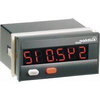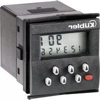
Codix 532 - Measuring equipment Kübler - Free user manual and instructions
Find the device manual for free Codix 532 Kübler in PDF.


User questions about Codix 532 Kübler
0 question about this device. Answer the ones you know or ask your own.
Ask a new question about this device
Download the instructions for your Measuring equipment in PDF format for free! Find your manual Codix 532 - Kübler and take your electronic device back in hand. On this page are published all the documents necessary for the use of your device. Codix 532 by Kübler.
USER MANUAL Codix 532 Kübler
for Thermoelectric couple sensors
J, K and N
Afficheur digital
text_image
8.88.88 5320.1Bitte beachten:
Nach DIN IEC 584 J (Fe-CuNi) -210,0 °C ... +1200,0 °C -346,0 °F ... +2192,0 °F K (Ni-CrNi) -200,0 °C ... +1372,0 °C -328,0 °F ... +2501,6 °F N (NiCrSi-NiSi) -200,0 °C ... +1300,0 °C -328,0 °F ... +2372,0 °F
1 Short description ....11
2 Safety instructions and warnings 11
2.1 Use according to the intended purpose .....11
3 Mounting 12
3.1 Installation 12
3.2 Electrical connection 12
4 Start-up 12
Programming 12
5.1 Switching to programming 12
5.2 Changing the parameter setting....13
5.3 Saving the parameter setting ....13
5.4 Programming 13
5.5 End of programming....15
6 Operation....15
6.1 Switching the display during operation....15
6.2 Saving the momentary value 16
7 Troubleshooting and alarm messages 16
8 Main technical features ....16
8.1 Electrical features....16
8.2 Mechanical features....16
8.3 Environmental conditions....17
9 Scope of delivery....17
10 Order code....17
11 Dimensions .... 17
Note :
The fields with a grey background contain the factory-set default values.
3
1 Short description
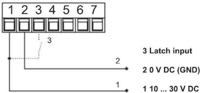
This digital display is an easy-to-use, microprocessor-controlled device for the display (and the acquisition) of measured temperature values. The temperatures are measured by means of J, K and N thermoelectric couple sensors. They can display either the current measured value, the maximum value or the minimum value. In case of power switch-off, the maximum and minimum values are stored in an EEPROM. The values are restored as soon as the display is powered again. The Latch input is isolated electrically from the signal input by means of an optocoupler. It allows storing the current measured value.
The supply voltage (10 .. 30 V DC) is isolated electrically from the signal input by means of a DC/DC converter.
2 Safety instructions and warnings
Only use this display

– in a way according to its intended purpose
- if its technical condition is perfect
- adhering to the operating instructions and the general safety instructions.
- Before carrying out any installation or maintenance work, make sure that the power supply of the digital display is switched off.
- Only use this digital display in a way according to its intended purpose.
- If its technical condition is perfect.
- Adhering to the operating instructions and the general safety instructions.
- Adhere to country or user specific regulations.
- The digital display is not intended for use in areas with risks of explosion and in the branches excluded by the standard EN 61010 Part 1.
- The digital display shall only operate if it has been correctly mounted in a panel, in accordance with the chapter "Main technical features".
2.1 Use according to the intended purpose
The digital display only may be used as a panel-mounted device. Applications of this product may be found in industrial processes and controls, in the branch of the manufacturing lines for the metal, wood, plastics, paper, glass, textile, etc., processing industries.
Overvoltages at the terminals of the digital display must be limited to the values of overvoltage category II.
If the digital display is used to monitor machines or processes in which, in case of a failure of the device or an error made by the operator, there might be risks of damaging the machine or causing accidents to the operators, it is up to you to take appropriate safety measures.
text_image
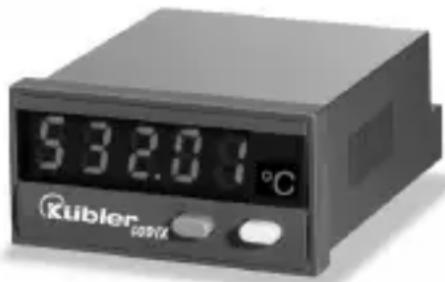
532.01°C Kubler cos/23 Mounting
3.1 Installation
- The digital display shall not be installed near to contactors or motor starters.
- We recommend the use of wire end ferrules in order to avoid short-circuits between adjacent terminals.
- In order to keep the interferences at the measuring input as low as possible, the signal and power supply wires must be routed separately.
- Use shielded cables for all signal/probe wirings and avoid routing the signal/probe wirings parallel to each other.
The shield shall only be grounded at one point in order to avoid ground loops.
3.2 Electrical connection
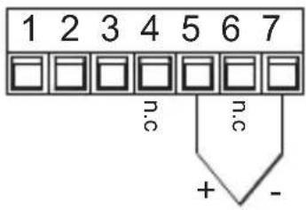
3.2.1 Thermoelectric couple sensor
text_image
1 2 3 4 5 6 7 n.c n.c + -4. Start-up
After switching on the supply voltage:
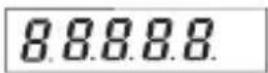
- a display test is carried out (Duration: 2 seconds)
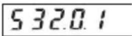
- Device type and software version are displayed (Duration: 2 seconds)
Important note:
Before carrying out any installation or maintenance work, make sure that the power supply of the digital display is switched off.
3.2.2 Supply voltage and Latch input connection
text_image
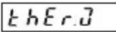
1 2 3 4 5 6 7 3 2 2 0 V DC (GND) 1 10 ... 30 V DC 3 Latch input- the selected probe is displayed (Duration: 2 seconds).
- the display is ready to operate and the measured value is displayed.
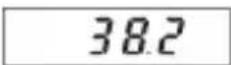
5. Programming
5.1 Switching to programming
To switch to the programming mode:
- switch the power supply of the device off, press simultaneously both keys on the front side, and then switch the power supply on again.
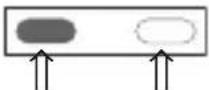
- The display shows the following message.
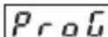
- release both keys. The first parameter to be set appears on the display. The display switches every second between the following messages

text_image
t h.t y P 1 s 3- press the left key to stop the display from switching. The last programmed parameter setting is displayed.
5.2 Changing the parameter setting
- press the right-hand/grey key to change the parameter setting by one value at a time
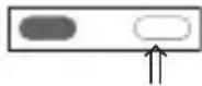
- to input numerical values, select first the decade with the left-hand/red key
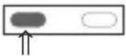
- the decade blinks
Selection in the menu
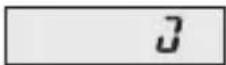
Thermoelectric couple J
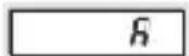
Thermoelectric couple K
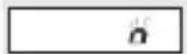
Thermoelectric couple N
5.4.2 Reference point compensation
A thermoelectric temperature measurement measures a (thermoelectric) voltage generated by a thermoelectric couple. The value of the thermoelectric voltage depends on the temperature difference between the measured point and the reference point.
In order to define accurately the temperature at the measured point, the temperature of the reference point must be constant and/or known. To do so, the internal and external reference points are differentiated.
For the internal reference point compensation, the device is fitted with an internal temperature sensor that measures the current temperature of the terminal. This temperature is 4. set now the numerical value using the right-hand/grey key
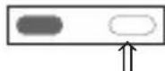
- to reach the following decade, press the left-hand/red key
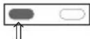
-
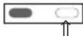
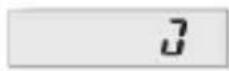
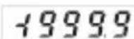
if negative numerical values are required, set the left decade to “-” or “-1”.
-
and press simultaneously the right/grey key..
Note : The fields with a grey background contain the factory-set default values.
used to compensate the measured thermoelectric voltage. This measuring method requires to connect the sensor with the terminal of the display by means of appropriate compensation lines. These terminals are the internal compensation point.
When using the external reference point compensation, the temperature of the reference point is maintained at a constant and known value by means of appropriate measures. The temperature sensor ist connected with the device, which is set to the constant temperature of the reference point, by means of a simple copper wire.
5.4.2 Reference point compensation (Continued)

Reference point compensation
Selection in the menu
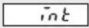
Internal reference point compensation
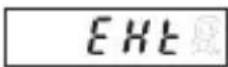
External reference point compensation Adhere to point 5.4.2.1
5.4.3 Decimal point
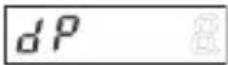
Decimal point
Selection in the menu
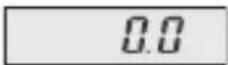
Resolution 0,1 °C/0,1 °F
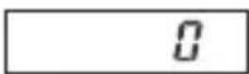
Resolution 1^ / 1^
5.4.5 Correction value
Inputting a correction value allows acting upon the displayed result. These correction values may be
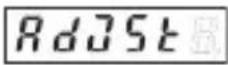
Setting the correction value
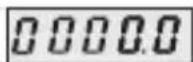
Selection in the menu
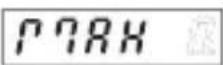
5.4.6 Maximum value acquisition
The maximum value may be saved and consulted during operation (see 6.1)
Selection in the menu
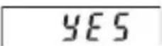
Maximum value acquisition on
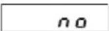
Maximum value acquisition off
5.4.2.1 External reference point temperature
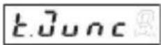
External reference point temperature
Selection in the menu

text_image
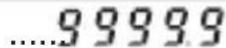
-9999 00000 ....09999Input of the known value of the external reference point temperature in 0,1 °C/0,1 °F, according to the temperature unit set
5.4.4 Temperature unit
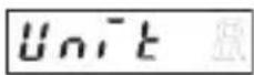
Unit
Selection in the menu
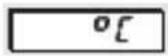
Display in ^
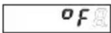
Display in °F
positive or negative. The input is always made with one decimal place.
Correction value in 0,1 °C/0,1 °F, depending on the unit selected
5.4.6.1 Resetting the maximum value
This allows defining whether the maximum value can be reset during operation or not. However, the maximum value can only be reset if the maximum value display is the active function (see 6.1). If the maximum value is reset, the current measured value becomes the new maximum value.
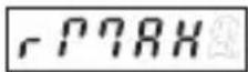
Selection in the menu
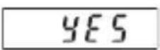
The maximum value can be reset using the red key
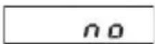
The maximum value cannot be reset
5.4.7 Minimum value acquisition
The minimum value may be saved and consulted during operation (see 6.1)
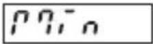
Selection in the menu
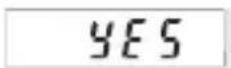
Minimum value acquisition on
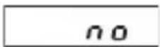
Minimum value acquisition off
5.5 End of programming
When programming is finished, end the prorgamming routine as follows:
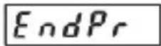
Selection in the menu
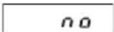
Programming restarts. The set values can be checked and modified.
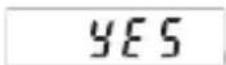
Programming is finished. The set values are used in operation.
5.4.7.1 Resetting the minimum value
This allows defining whether the minimum value can be reset during operation or not. However, the minimum value can only be reset if the minimum value display is the active function (see 6.1). If the minimum value is reset, the current measured value becomes the new minimum value.
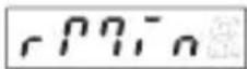
Selection in the menu
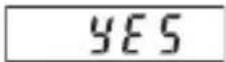
The minimum value can be reset using the red key
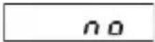
The minimum value cannot be reset
6. Operation
6.1 Switching the display during operation
press the right-hand/grey key to select among the following functions:
-current measured value
-minimum value
-maximum value
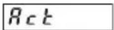
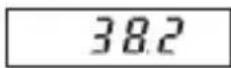
Press the key once to display the designation of the active display function for 2 seconds. If, during this time, the right-hand grey key is pressed a second time, the display switches to the following display function. This is confirmed by a 2-second display of the designation of the new function. After these 2 seconds, the display shows, depending on the selection, the maximum value, the minimum value or the current measured value..
- Current measured value, press once the right-hand/grey key
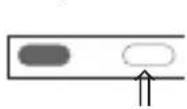
for 2 s:
after 2 s:
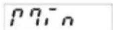
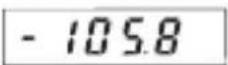
- Minimum value (when active), press once the right-hand/grey key
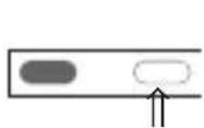
for 2 s:
after 2 s:
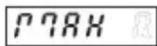
- Maximum value (when active), press once the right-hand/grey key 1x drücken
for 2 s:
after 2 s:
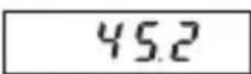
- Current measured value, press once the right-hand/grey key
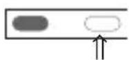
for 2 s:
after 2 s:
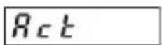
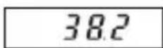
6.2 Saving the momentary value (Display-Latch)
In case of a High Signal at the Latch input, the current measured value is frozen on the display. The minimum and maximum value acquisition continues operating in the background.
7 Troubleshooting and alarm messages
7.1 Display does not light up
If the display does not light up, check the supply voltage or the power supply cables. Do not open the housing by force.
7.2 Measuring rang overflow or underflow
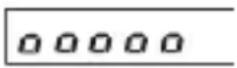
Measuring range overflow Ranges see 8.1
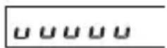
Measuring range underflow Ranges see 8.1
7.3 Input problems
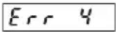
Probe broken or input signal exceeds the allowable range
8 Main technical features
Operation: by means of two front panel keys
Display: 5-digit display, red 7-segment LED's, Height of the figures 8 mm
Display range: (see temperature range), with leading zeros suppression Measuring range overflow, indicated by ooooo on the display. Measuring range underflow, indicated by uuuuu on the display.
8.1 Electrical features
Input: Thermoelement-sensor
J (Fe-CuNi)
K (Ni-CrNi)
N (NiCrSi-NiSi)
Temperature ranges:
after DIN IEC 548
J (Fe-CuNi) -210,0 °C ... +1200,0 °C
-346,0 °F ... +2192,0 °F
K (Ni-CrNi) -200,0 °C ... +1372,0 °C
-328,0 °F ... +2501,6 °F
N (NiCrSi-NiSi) -200,0 °C ... +1372,0 °C
-328,0 °F ... +2372,0 °F
Resolution: 0,1°C (0,1°F) or 1°C (1°F)
Reference point compensation:
internal or external (programmable)
Reference point error:
+/-1,0 °C typ.
+/-3,0 °C max.
Linearity error:
< 0,4 % for the whole measuring range at an ambient temperature of 20°C
Temperature drift:
0,1 K/Kambient
Measuring rate:
5 measurements/second, fixed
Display refresh:
1 ... 2 times per second
Display Latch input:
Display stop for the current measured value, active for log. 1 Switching log. 0: 0 ... 2 VDC level log. 1: 4 ... 30 VDC
Supply voltage:
10 ... 30 V DC, electrically separated, with Verpolschutz
Current consumption:
max. 40 mA
Test voltage: 500 Veff; 50/60 Hz; 1 min
Data backup: EEPROM
8.2 Mechanical features
Housing: Housing for control panel 48 x 24 mm according to DIN 43 700, RAL 7021
Dimensions: (W x H x D):
48 x 24 x 66 mm
Panel cut-out: (W x H):
45+0,6 × 22,2+0,3 mm
Mounting depth:
approximately 59 mm
Weight: approximately 50 g
Protection level:
IP 65 (on the front side)
Connection: Screw terminal, RM 5.08, 7 poles
Connection diameter:
single-wire 0,14 .. 1,5 mm2
thin wire 0,14 .. 1,5 mm2
wire dimensionsAWG 26-16
8.3 Environment conditions
EMC:
Interference emissions EN 55011 Class B
Interference resistance EN 61000-6-2
Operating temperature:
-20 °C ... +65 °C, relative humidity < 85%
Storage temperature:
-25 °C ... +70 °C
9 Scope of delivery
Digital display
Clamp
Front panel for clamp mounting,
Panel cut-out 50 x 25 mm
Front panel for screw mounting,
Panel cut-out 50 x 25 mm
Seal
Multilingual operating instructions
1 set of self-adhesive symbols
10 Order code
6.532.012.300
11 Digital display dimensions
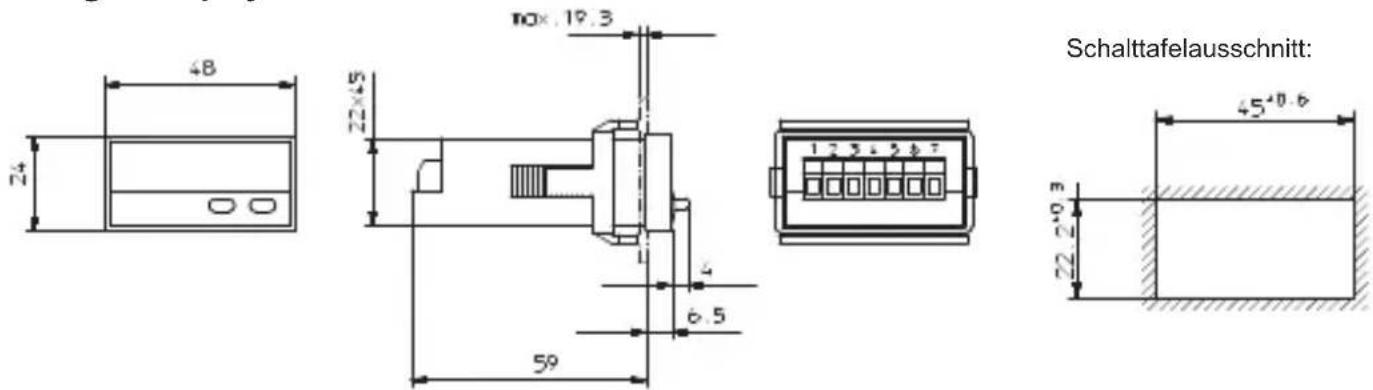
Mounting frame
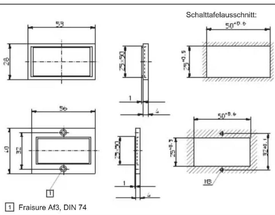
1 Fraisure Af3, DIN 74
Sommaire
text_image
532.01°C Kubler cosyl3 Montage
3.1 Installation
J (Fe-CuNi) -210,0 °C ... +1200,0 °C -346,0 °F ... +2192,0 °F
K (Ni-CrNi) -200,0 °C... +1372,0 °C -328,0 °F ... +2501,6 °F
N (NiCrSi-NiSi) -200,0 °C ... +1372,6 °C -328,0 °F ... +2372,0 °F
+/-1,0 °C tip. +/-3,0 °C maxi.
J (Fe-CuNi) -210,0°C ... +1200,0 °C -328,0 °F ... +2192,0 °F K (Ni-CrNi) -200,0 °C ... +1372,0 °C -328,0 °F ... +2501,6 °F N (NiCrSi-NiSi) -200,0 °C ... +1372,0 °C -328,0 °F ... +2372,0 °F
Dimensioni (L x A x P):
48 × 24 × 66 mm
J (Fe-CuNi) -210,0 °C ... +1200,0 °C -346,0 °F ... +2192,0 °F
K (Ni-CrNi) -200,0 °C... +1372,0 °C -328,0 °F ... +2501,6 °F
N (NiCrSi-NiSi) -200,0 °C ... +1372,6 °C -328,0 °F ... +2372,0 °F
+/-1,0 °C tip. +/-3,0 °C maxi.