
HW001G - Pressure washer MAKITA - Free user manual and instructions
Find the device manual for free HW001G MAKITA in PDF.

User questions about HW001G MAKITA
0 question about this device. Answer the ones you know or ask your own.
Ask a new question about this device
Download the instructions for your Pressure washer in PDF format for free! Find your manual HW001G - MAKITA and take your electronic device back in hand. On this page are published all the documents necessary for the use of your device. HW001G by MAKITA.
USER MANUAL HW001G MAKITA
natural_image
Line drawing of a mechanical device with no visible text or symbols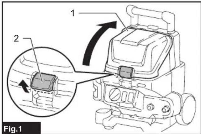
natural_image
Technical line drawing of a mechanical device with internal components and a hand adjusting the part (no text or symbols present)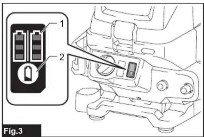

natural_image
Diagram of a tool with threaded ends and a spiral arrow indicating motion or force (no text or symbols)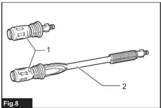
natural_image
Three-step illustration showing a hand holding a flashlight with a no-smoking symbol, no text or labels present.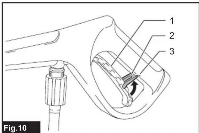

natural_image
Two technical illustrations of a cleaning machine, one with a handle and the other without a prohibition sign (no text or symbols on the devices themselves)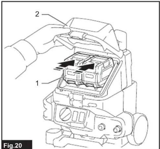
natural_image
Line drawing of a gas pump connected to a hose, with a speech bubble showing a faucet tip (no text or symbols present)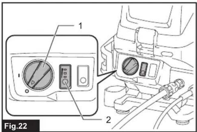
natural_image
Line drawing of a pressure pump device with hoses and control lever (no text or symbols)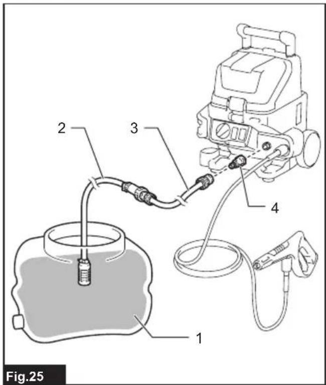
natural_image
Line drawing of a person using a fuel pump gun, labeled with number 1 (no text or symbols on diagram)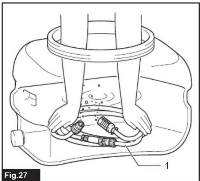
natural_image
Technical line drawing of a mechanical assembly with hands and labeled parts (no text or symbols)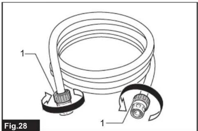
natural_image
Technical line drawing of a mechanical component with a cable and connector (no text or symbols)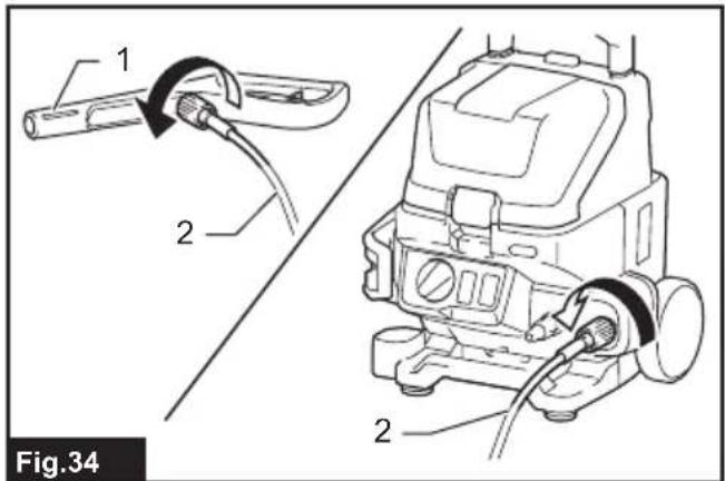
natural_image
Diagram showing hand valve adjustment and electrical component assembly (no text or symbols)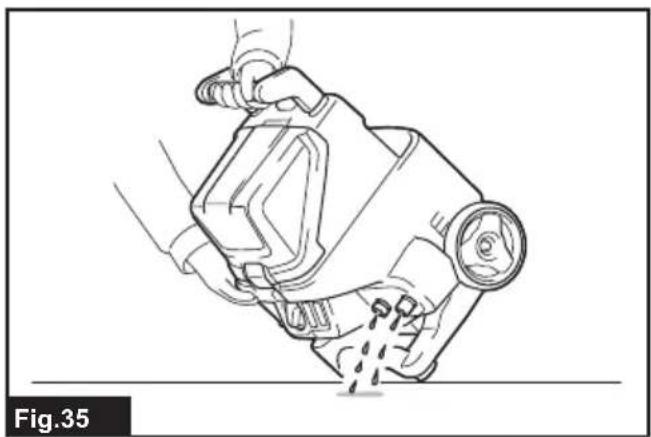
natural_image
Line drawing of a hand using a tool to lift a mechanical component, labeled Fig.35 (no text or symbols on the diagram itself)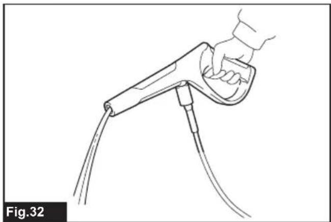
natural_image
Line drawing of a hand holding a handheld device with cables (no text or symbols)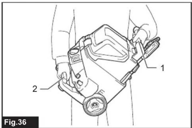
natural_image
Line drawing of a person pushing a small cart with a handle, no text or symbols present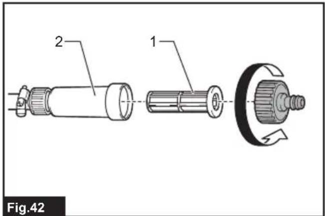
natural_image
Technical line drawing of a mechanical device with internal components (no text or symbols)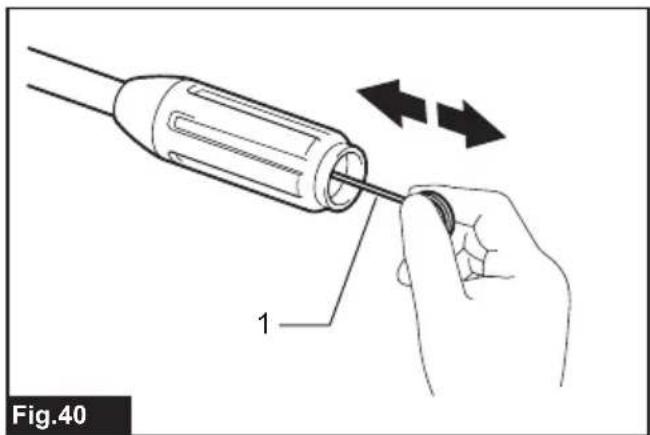
natural_image
Illustration of a hand using a screwdriver to adjust a component (no text or symbols present)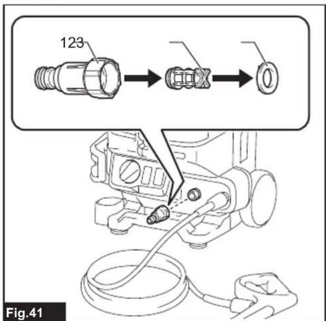
natural_image
Line drawing of a brush tip with a circular base and pointed tip, labeled Fig.45 (no text or symbols on the diagram itself)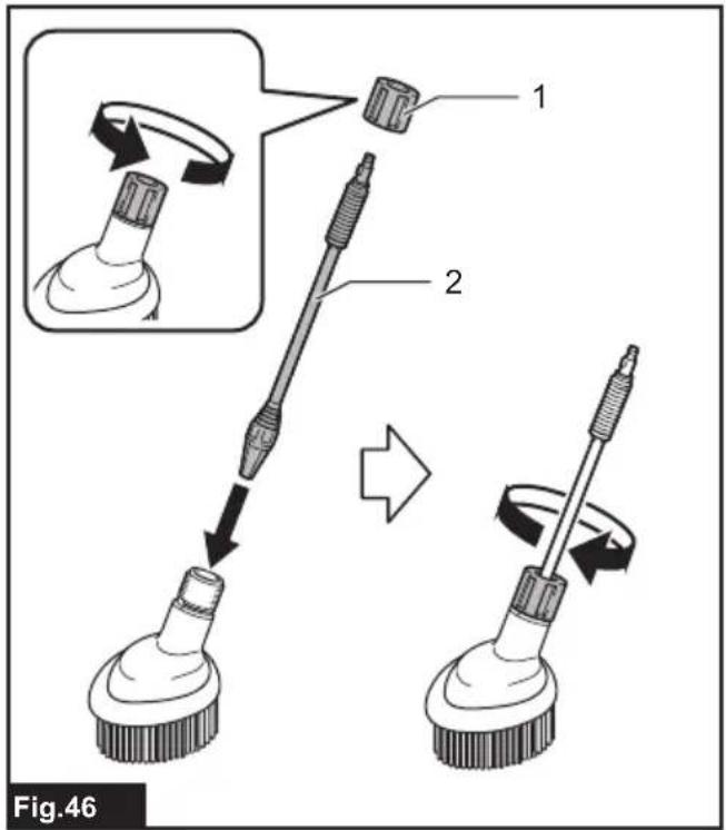
natural_image
Line drawing of a cylindrical tool emitting vapor, labeled Fig.47 (no text or symbols on the diagram itself)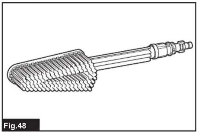
natural_image
Technical line drawing of a mechanical component with threaded ends and a central shaft (no text or symbols)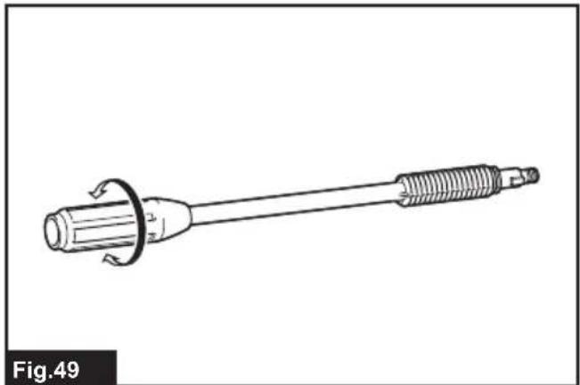
natural_image
Technical line drawing of a mechanical tool with threaded end and flange (no text or symbols)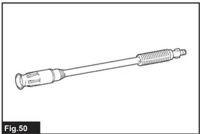
natural_image
Line drawing of a mechanical tool with threaded end and flange (no text or symbols)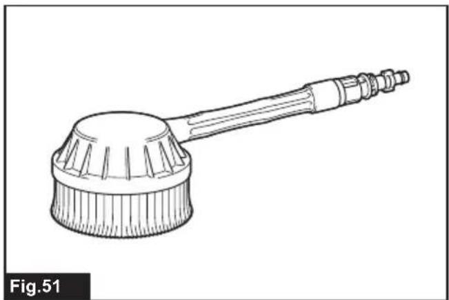
natural_image
Line drawing of a cleaning brush with a handle and spout, labeled Fig.51 (no text or symbols on the diagram itself)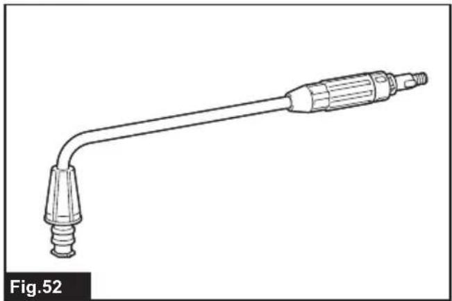
natural_image
Line drawing of a handheld pressure tool with a pointed tip and threaded end (no text or symbols)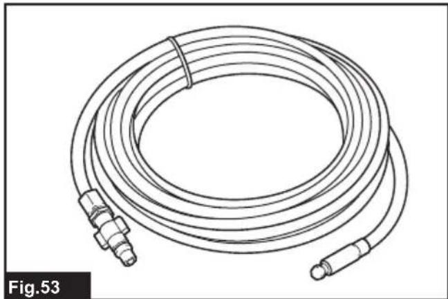
natural_image
Line drawing of a coiled industrial hose with two connectors (no text or symbols)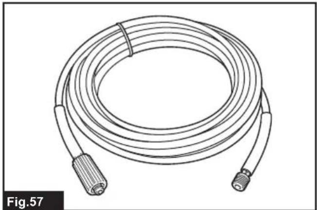
natural_image
Line drawing of a coiled cable with two connectors, labeled Fig.57 (no text or symbols on the diagram itself)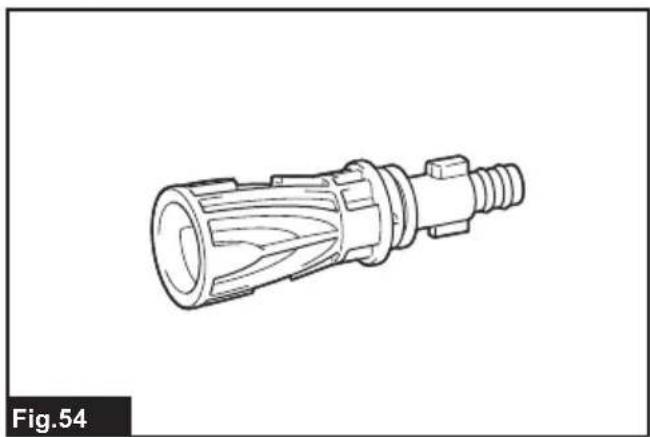
natural_image
Technical line drawing of a mechanical connector component (no text or symbols)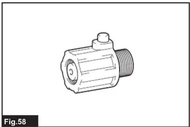
natural_image
Technical line drawing of a mechanical component (no text or symbols)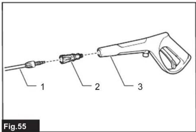
natural_image
Line drawings of five different types of screwdrivers, shown in different angles (no text or symbols)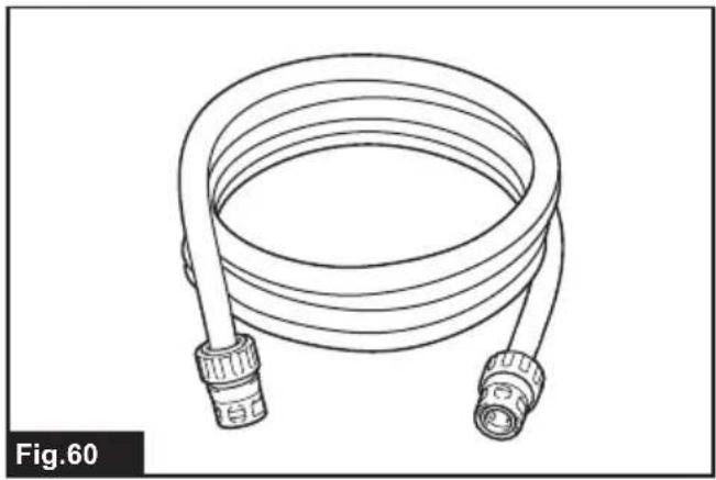
natural_image
Line drawing of a coiled hose with two connectors (no text or symbols)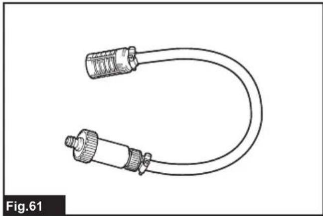
natural_image
Line drawing of a U-shaped cable with two connectors (no text or symbols)WARNING
- Machines shall not be used by children. Children should be supervised to ensure that they do not play with the machine.
- This machine is not intended for use by persons (including children) with reduced physical, sensory, or mental capabilities, or lack of experience and knowledge.
- This machine has been designed for use with the cleaning agent supplied or recommended by the manufacturer. The use of other cleaning agents or chemicals may adversely affect the safety of the machine.
- During use of high pressure cleaners, aerosols may be formed. Inhalation of aerosols can be hazardous to health.
- Depending on the application, shielded nozzles can be used for high pressure cleaning, which will reduce the emission of hydrous aerosols dramatically. However, not all applications allow the use of such a device. If shielded nozzles are not applicable for the protection against aerosols, a respiratory mask of class FFP 2 or equivalent may be needed, depending on the cleaning environment.
- The employer shall perform a risk assessment in order to specify the necessary protective measures regarding aerosols, depending on the surface to be cleaned and its environment. Respiratory masks of class FFP 2, an equivalent or higher are suitable for the protection against hydrous aerosols.
- High pressure jets can be dangerous if subject to misuse. The jet must not be directed at persons, live electrical equipment or the machine itself.
- Do not use the machine within range of persons unless they wear protective clothing.
- Do not direct the jet against yourself or others in order to clean clothes or foot-wear.
- Risk of explosion – Do not spray flammable liquids.
-
High pressure cleaners shall not be used by children or untrained personnel.
-
High pressure hoses, fittings and couplings are important for the safety of the machine. Use only hoses, fittings and couplings recommended by the manufacturer.
- To ensure machine safety, use only original spare parts from the manufacturer or approved by the manufacturer.
• Always be sure that the machine is switched off and battery cartridges are removed before carrying out any work on the tool. - Do not use the machine if important parts of the machine are damaged, e.g. safety devices, high pressure hoses, trigger gun.
- Always remove the battery cartridges when leaving the machine unattended.
- Comply with the requirements of the local water supply company.
• For European countries:
According to EN12729 (BA), the appliance can also be connected to the mains drinking water supply if a backflow preventer valve with drain facility is installed in the supply hose.
SPECIFICATIONS
| Model: HW001G | ||
| Max. flow rate *1 7.0 L/min | ||
| Water flow rate *2 Mode 3 (High | mode) 5.5 L/min | |
| Mode 2 (Middle mode) 4.2 L/min | ||
| Mode 1 (Low mode) 3.0 L/min | ||
| Max. permissible pressure 11.5 MPa | ||
| Working pressure *2 Mode 3 (High mode) 8.5 MPa | ||
| Max. feed pressure | 1.0 MPa | |
| Max. feed temperature | 40 °C | |
| Max. suction height | 1.0 m | |
| Rated voltage | D.C. 36 V - 40 V max | |
| Dimensions (L x W x H) *3 | 344 mm x 383 mm x 520 mm | |
| Net weight | 10.3 - 13.4 kg | |
| Water protection | IPX5 | |
*1: When using the trigger gun without the nozzles.
*2: When using the vario spray nozzle and extension.
*3: When the handle is folded and without hoses.
- Due to our continuing program of research and development, the specifications herein are subject to change without notice.
- Specifications may differ from country to country.
- The weight may differ depending on the attachment(s), including the battery cartridge. The lightest and heaviest combinations, according to EPTA-Procedure 01/2014, are shown in the table.
Applicable battery cartridge and charger
| Battery cartridge BL4020 / BL4025 / BL4040 / BL4050F* / BL4080F* | *: Recommended battery |
| Charger DC40RA / DC40RB / DC40RC |
- Some of the battery cartridges and chargers listed above may not be available depending on your region of residence.
WARNING: Only use the battery cartridges and chargers listed above. Use of any other battery cartridges and chargers may cause injury and/or fire.
Symbols
The followings show the symbols which may be used for the equipment. Be sure that you understand their meaning before use.

Take particular care and attention.


Read instruction manual.
Do not connect to a potable water faucet.
Do not direct the jet at people including yourself, animals, and live electrical equipments.

Ni-MH Li-ion
Only for EU countries
Due to the presence of hazardous components in the equipment, waste electrical and electronic equipment, accumulators and batteries may have a negative impact on the environment and human health. Do not dispose of electrical and electronic appliances or batteries with household waste!
In accordance with the European Directive on waste electrical and electronic equipment and on accumulators and batteries and waste accumulators and batteries, as well as their adaptation to national law, waste electrical equipment, batteries and accumulators should be stored separately and delivered to a separate collection point for municipal waste, operating in accordance with the regulations on environmental protection.
This is indicated by the symbol of the crossed-out wheeled bin placed on the equipment.

Guaranteed sound power level according to EU Outdoor Noise Directive.

Sound power level according to Australia NSW Noise Control Regulation.
Intended use
This machine is intended for cleaning stubborn dirt by using water jet. This machine is intended for both commercial use and household use.
Noise
The typical A-weighted noise level determined according to EN60335-2-79:
Sound pressure level ( L_pA ): 71 dB (A)
Uncertainty (K): 3.2 dB (A)
The noise level under working may exceed 80 dB (A).
NOTE: The declared noise emission value(s) has been measured in accordance with a standard test method and may be used for comparing one tool with another.
NOTE: The declared noise emission value(s) may also be used in a preliminary assessment of exposure.
WARNING: Wear ear protection.
WARNING: The noise emission during actual use of the power tool can differ from the declared value(s) depending on the ways in which the tool is used especially what kind of workpiece is processed.
WARNING: Be sure to identify safety measures to protect the operator that are based on an estimation of exposure in the actual conditions of use (taking account of all parts of the operating cycle such as the times when the tool is switched off and when it is running idle in addition to the trigger time).
Vibration
The vibration total value (tri-axial vector sum) determined according to EN60335-2-79:
Vibration emission (ah): 3.2 m/s²
Uncertainty (K) : 1.5 m/s ^2
NOTE: The declared vibration total value(s) has been measured in accordance with a standard test method and may be used for comparing one tool with another.
NOTE: The declared vibration total value(s) may also be used in a preliminary assessment of exposure.
WARNING: The vibration emission during actual use of the power tool can differ from the declared value(s) depending on the ways in which the tool is used especially what kind of workpiece is processed.
WARNING: Be sure to identify safety measures to protect the operator that are based on an estimation of exposure in the actual conditions of use (taking account of all parts of the operating cycle such as the times when the tool is switched off and when it is running idle in addition to the trigger time).
Declarations of Conformity
For European countries only
The Declarations of conformity are included in Annex A to this instruction manual.
SAFETY WARNINGS
General power tool safety warnings
WARNING Read all safety warnings, instructions, illustrations and specifications provided with this power tool. Failure to follow all instructions listed below may result in electric shock, fire and/or serious injury.
Save all warnings and instructions for future reference.
The term "power tool" in the warnings refers to your mains-operated (corded) power tool or battery-operated (cordless) power tool.
IMPORTANT SAFETY WARNINGS
WARNING: Read all safety warnings and all instructions. Failure to follow the warnings and instructions may result in electric shock, fire and/or serious injury.
Save all warnings and instructions for future reference.
WARNING – When using this product, basic precautions should always be followed, including the following:
Work area safety
- Keep operating area clear of all persons.
- Do not overreach or stand on unstable supports. Keep good footing and balance at all times.
- Always place the high pressure washer body on a level and stable surface. Avoid areas where the ejected water will run or pool.
- Before cleaning, check the surroundings and objects to be cleaned. High pressure jets can scrape away paint or other surface treatments including toxic chemicals. Take the preventive measures if necessary.
- Be careful not to trip over by the hose of the high pressure washer. Always be aware of the configuration of the hose during operation.
- During use, a small amount of water will come out from the bottom of the high pressure washer. Avoid locating the high pressure washer in the areas where you don't want to wet.
Personal safety
-
To protect against the jet and objects by the jet, operators should wear appropriate clothing such as safety boots, safety gloves, safety helmets with visors, hearing protection, etc.
-
Do not use the high pressure washer within range of persons unless they wear protective clothing.
- To reduce the risk of injury, close supervision is necessary when the product is used near children.
- If connection is made to a potable water system, the system shall be protected against backflow.
- Water that has flowed through backflow preventer is considered to be non-potable.
Electrical safety
- Never touch battery cartridges with wet hands.
- Do not use the machine if the important parts of the machine are damaged, e.g. safety devices, high pressure hoses, or the trigger gun.
Power tool use and care
- Read all the instructions before using the product.
- Know how to stop the high pressure washer and bleed pressures quickly. Be thoroughly familiar with the controls.
- High pressure jets can be dangerous if misused. The jet must not be directed at people, live electrical equipment, or the machine itself.
- This machine is not intended for use by persons (including children) with reduced physical, sensory, or mental capabilities, or lack of experience and knowledge.
- Children should be supervised to ensure that they do not play with the appliance.
- Do not spray flammable and/or toxic liquids. This may cause an explosion, intoxication, or damage to the machine.
- Do not direct the jet against yourself or others in order to clean clothes or foot-wear.
- High pressure hoses, fittings and couplings are important for the safety of the machine. Use only hoses, fittings and couplings recommended by the manufacturer.
- Follow the instructions when changing accessories.
- Keep handles dry, clean, and free of oil or grease.
- Stay alert – watch what you are doing.
- Do not operate the product when fatigued or under the influence of alcohol or drugs.
- Do not run the high pressure washer without water for longer than one minute. It will damage the motor, resulting in malfunction.
- Always turn off the power and shut off the water mains when leaving the high pressure washer unattended.
- Be wary of the kickback. The trigger gun recoils when the high pressure jet is ejected from the nozzle. Hold the trigger gun firmly to prevent accidental injuries.
-
Check for damaged or worn parts before use. Also make sure that the hose is properly connected and there is no leakage during operation. Operating the machine with functional defects may cause an accident.
-
This machine has been designed for use with the cleaning agent supplied or recommended by the manufacturer. The use of other cleaning agents or chemicals may adversely affect the safety of the machine.
- Do not pull the hose to move the high pressure washer body. This will damage the hose and connecting parts and result in a short circuit or functional defects.
- Do not put heavy objects on the hose or let vehicles drive over it.
- Always discharge the residual pressure in the trigger gun before disconnecting the hose.
- When connecting the hose to the water mains, observe the instructions of your local water-works department or company.
- If the high pressure washer is dropped or hits against an hard object, be sure to check for damage and crack. Using the high pressure washer damaged may generate smoke, fire, or cause electric shock, which result in personal injury.
- During use of high pressure cleaners, aerosols may be formed. Inhalation of aerosols can be hazardous to health.
- Depending on the application, shielded nozzles can be used for high pressure cleaning, which will reduce the emission of hydrous aerosols dramatically. However, not all applications allow the use of such a device. If shielded nozzles are not applicable for the protection against aerosols, a respiratory mask of class FFP 2 or equivalent may be needed, depending on the cleaning environment.
- The employer shall perform a risk assessment in order to specify the necessary protective measures regarding aerosols, depending on the surface to be cleaned and its environment. Respiratory masks of class FFP 2, an equivalent or higher are suitable for the protection against hydrous aerosols.
- Prevent unintentional starting. Ensure the switch is in the off-position before connecting to battery pack, picking up or carrying the appliance. Carrying the appliance with your finger on the switch or energizing appliance that have the switch on invites accidents.
- Disconnect the battery pack from the appliance before making any adjustments, changing accessories, or storing appliance. Such preventive safety measures reduce the risk of starting the appliance accidentally.
- Do not modify or attempt to repair the appliance or the battery pack except as indicated in the instructions for use and care.
- Do not apply the water jet to the same area continuously. The object may break and cause an injury.
- Do not wash the machine with the water jet of this machine. The machine may break or parts of the machine may come off and cause an injury.
- To avoid risk of electric shock, do not direct the water jet against the machine while the machine is turned on.
Battery tool use and care
-
Recharge only with the charger specified by the manufacturer. A charger that is suitable for one type of battery pack may create a risk of fire when used with another battery pack.
-
Use power tools only with specifically designated battery packs. Use of any other battery packs may create a risk of injury and fire.
-
When battery pack is not in use, keep it away from other metal objects, like paper clips, coins, keys, nails, screws or other small metal objects, that can make a connection from one terminal to another. Shorting the battery terminals together may cause burns or a fire.
-
Under abusive conditions, liquid may be ejected from the battery; avoid contact. If contact accidentally occurs, flush with water. If liquid contacts eyes, additionally seek medical help. Liquid ejected from the battery may cause irritation or burns.
-
Do not use a battery pack or tool that is damaged or modified. Damaged or modified batteries may exhibit unpredictable behaviour resulting in fire, explosion or risk of injury.
-
Do not expose a battery pack or tool to fire or excessive temperature. Exposure to fire or temperature above 130 °C may cause explosion.
-
Follow all charging instructions and do not charge the battery pack or tool outside the temperature range specified in the instructions. Charging improperly or at temperatures outside the specified range may damage the battery and increase the risk of fire.
Service
- Follow the maintenance instructions specified in the manual.
- To ensure machine safety, use only original spare parts from the manufacturer or approved by the manufacturer.
- Have your high pressure washer serviced by a qualified repair person using only identical replacement parts. This will ensure that the safety of the high pressure washer is maintained.
- In case of breakdown or malfunction of the high pressure washer, immediately switch it off and remove the battery cartridge(s). Contact your local dealer or service center.
Additional safety warnings
- Comply with the requirements of the local water supply company.
- Do not use the machine when there is a risk of lightning.
- When you use the machine on muddy ground, wet slope, or slippery place, pay attention to your footing.
- Do not replace the battery in the rain.
- Do not submerge the machine into a puddle.
- Do not leave the machine unattended outdoors in the rain.
-
When storing the machine, avoid direct sunlight and rain, and store it in a place where it does not get hot or humid.
-
Do not sit on the machine or use the machine as a step stool. Doing so may cause accident or malfunction of machine.
SAVE THESE INSTRUCTIONS.
⚠ WARNING: DO NOT let comfort or familiarity with product (gained from repeated use) replace strict adherence to safety rules for the subject product.
MISUSE or failure to follow the safety rules stated in this instruction manual may cause serious personal injury.
Important safety instructions for battery cartridge
- Before using battery cartridge, read all instructions and cautionary markings on (1) battery charger, (2) battery, and (3) product using battery.
- Do not disassemble or tamper with the battery cartridge. It may result in a fire, excessive heat, or explosion.
- If operating time has become excessively shorter, stop operating immediately. It may result in a risk of overheating, possible burns and even an explosion.
-
If electrolyte gets into your eyes, rinse them out with clear water and seek medical attention right away. It may result in loss of your eyesight.
-
Do not short the battery cartridge:
(1) Do not touch the terminals with any conductive material.
(2) Avoid storing battery cartridge in a container with other metal objects such as nails, coins, etc.
(3) Do not expose battery cartridge to water or rain.
A battery short can cause a large current flow, overheating, possible burns and even a breakdown.
-
Do not store and use the tool and battery cartridge in locations where the temperature may reach or exceed 50 °C (122 °F).
-
Do not incinerate the battery cartridge even if it is severely damaged or is completely worn out. The battery cartridge can explode in a fire.
-
Do not nail, cut, crush, throw, drop the battery cartridge, or hit against a hard object to the battery cartridge. Such conduct may result in a fire, excessive heat, or explosion.
-
Do not use a damaged battery.
-
The contained lithium-ion batteries are subject to the Dangerous Goods Legislation requirements. For commercial transports e.g. by third parties, forwarding agents, special requirement on packaging and labeling must be observed. For preparation of the item being shipped, consulting an expert for hazardous material is required. Please also observe possibly more detailed national regulations. Tape or mask off open contacts and pack up the battery in such a manner that it cannot move around in the packaging.
-
When disposing the battery cartridge, remove it from the tool and dispose of it in a safe place. Follow your local regulations relating to disposal of battery.
-
Use the batteries only with the products specified by Makita. Installing the batteries to non-compliant products may result in a fire, excessive heat, explosion, or leak of electrolyte.
-
If the tool is not used for a long period of time, the battery must be removed from the tool.
-
During and after use, the battery cartridge may take on heat which can cause burns or low temperature burns. Pay attention to the handling of hot battery cartridges.
-
Do not touch the terminal of the tool immediately after use as it may get hot enough to cause burns.
-
Do not allow chips, dust, or soil stuck into the terminals, holes, and grooves of the battery cartridge. It may cause heating, catching fire, burst and malfunction of the tool or battery cartridge, resulting in burns or personal injury.
-
Unless the tool supports the use near high-voltage electrical power lines, do not use the battery cartridge near high-voltage electrical power lines. It may result in a malfunction or breakdown of the tool or battery cartridge.
-
Keep the battery away from children.
SAVE THESE INSTRUCTIONS.
CAUTION: Only use genuine Makita batteries. Use of non-genuine Makita batteries, or batteries that have been altered, may result in the battery bursting causing fires, personal injury and damage. It will also void the Makita warranty for the Makita tool and charger.
Tips for maintaining maximum battery life
-
Charge the battery cartridge before completely discharged. Always stop tool operation and charge the battery cartridge when you notice less tool power.
-
Never recharge a fully charged battery cartridge. Overcharging shortens the battery service life.
-
Charge the battery cartridge with room temperature at 10 °C - 40 °C ( 50 °F - 104 °F ). Let a hot battery cartridge cool down before charging it.
-
When not using the battery cartridge, remove it from the tool or the charger.
-
Charge the battery cartridge if you do not use it for a long period (more than six months).
CAUTION: Always be sure that the machine is switched off and the battery cartridges are removed before adjusting or checking function on the machine.
CAUTION: Always switch off the machine before installing or removing of the battery cartridge.
CAUTION: Hold the machine and the battery cartridge firmly when installing or removing battery cartridge. Failure to hold the machine and the battery cartridge firmly may cause them to slip off your hands and result in damage to the machine and battery cartridge and a personal injury.
CAUTION: Make sure that you lock the battery cover before use. Otherwise, mud, dirt, or water may cause damage to the product or the battery cartridge.
CAUTION: Always install the battery cartridge fully. If not, it may accidentally fall out of the machine, causing injury to you or someone around you.
CAUTION: Do not install the battery cartridge forcibly. If the cartridge does not slide in easily, it is not being inserted correctly.
CAUTION: Hold the battery cover firmly when installing or removing the battery cartridge.
To install the battery cartridge;
- Pull up the locking lever, and then open the battery cover.
▶ Fig.1: 1. Battery cover 2. Locking lever
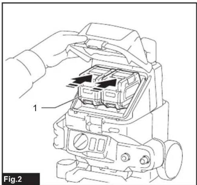
- Align the tongue on the battery cartridge with the slot on the machine, and then slide the cartridge until it locks in place with a little click.
▶ Fig.2: 1. Battery cartridge
- Close the battery cover and push it until it is latched with the locking lever.
To remove the battery cartridge;
- Pull up the locking lever and open the battery cover.
- Pull out the battery cartridge from the machine while sliding the button on the front of the cartridge.
- Close the battery cover and push it until it is latched with the locking lever.
You can check the remaining battery capacity by pressing the battery check button.
▶ Fig.3: 1. Battery indicator 2. Battery check button
Battery indicator status Remaining
| On Off | Blinking | battery capacity |
| 50% to 100% | ||
| 20% to 50% | ||
| 0% to 20% | ||
| Charge the battery |
NOTE: The indicator lamp for remaining battery capacity is just for a reference. The actual battery capacity may differ depending on the usage conditions or ambient temperature.
NOTE: The lamp automatically goes off after a few seconds.
NOTE: If two battery cartridges are installed, the battery installed on the left side is used first.
NOTE: If two battery cartridges are installed, the machine automatically switches the battery when the battery in use becomes empty.
NOTE: You can check the remaining battery capacity without turning on the power switch.
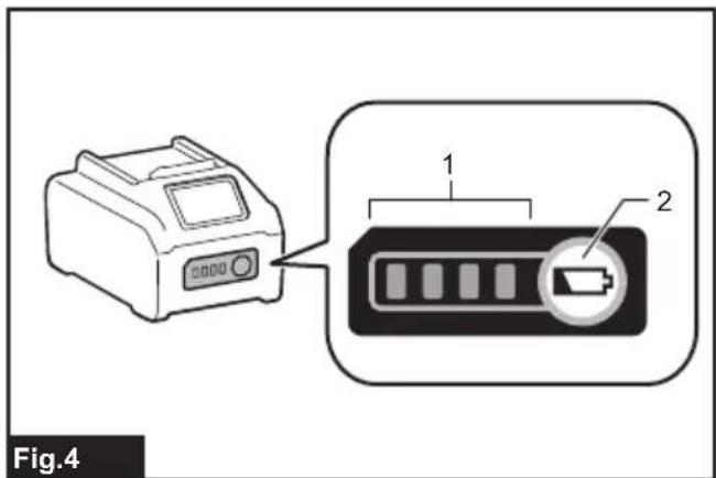
Press the check button on the battery cartridge to indicate the remaining battery capacity. The indicator lamps light up for a few seconds.
▶ Fig.4: 1. Indicator lamps 2. Check button
Indicator lamps Remaining
capacity
Lighted Off Blinking
75% to 100%
50% to 75%
25% to 50%
0% to 25%
Charge the battery.
The battery may have malfunctioned.
NOTE: Depending on the conditions of use and the ambient temperature, the indication may differ slightly from the actual capacity.
NOTE: The first (far left) indicator lamp will blink when the battery protection system works.
Machine/battery protection system
The machine is equipped with a machine/battery protection system. This system automatically cuts off power to the motor to extend machine and battery life. The machine will automatically stop during operation if the machine or battery is placed under one of the following conditions:
Overload protection
When the machine or battery is operated in a manner that causes it to draw an abnormally high current, the machine automatically stops and the speed indicator blinks in green. In this situation, turn the machine off and stop the application that caused the machine to become overloaded. Then turn the machine on to restart.
Overheat protection
When the machine is overheated, the machine stops automatically and the speed indicator lights up in red. In this case, let the machine and battery cool before turning the machine on again.
NOTE: The speed indicator blinks in red when the battery is overheated.
Overdischarge protection
When the battery capacity is not enough, the machine stops automatically and the speed indicator blinks in red. In this case, remove the battery from the machine and charge the battery or change the battery to fully charged one.
Protections against other causes
Protection system is also designed for other causes that could damage the machine and allows the machine to stop automatically. Take all the following steps to clear the causes, when the machine has been brought to a temporary halt or stop in operation.
- Turn the machine off, and then turn it on again to restart.
- Charge the battery(ies) or replace it/them with recharged battery(ies).
- Let the machine and battery(ies) cool down.
If no improvement can be found by restoring protection system, then contact your local Makita Service Center.
NOTICE: If the machine stops due to a cause not described above, refer to the section for troubleshooting.
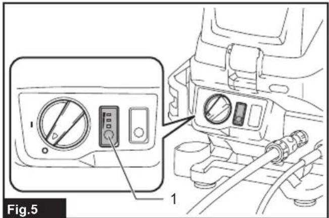
Mode switching button
The speed can be changed in three levels. To change the speed mode, press the mode switching button. When you change the speed mode, the corresponding speed indicators light up.
▶ Fig.5: 1. Mode switching button
NOTE: You cannot change the mode while the machine is turned on. Change the mode when the machine is turned off and the battery is installed to the machine.
NOTE: If the speed indicator lights up in red or blinks in red or green, refer to the instructions for machine/battery protection system.
Power switch
⚠ WARNING: Always turn off the main power switch when not in use.
NOTICE: Do not turn the power switch forcibly. This may cause the switch to malfunction.
To turn on the machine, turn the power switch clockwise, and to turn off the machine, turn the power switch counterclockwise.
▶ Fig.6: 1. Power switch
NOTE: The battery indicators will light up for a few seconds just after turning the machine on.
NOTE: If you install the battery cartridge to the machine when the power switch is in the turned-on position, the speed indicator blinks in green. Turn the power switch to the turned-off position, and then install the battery cartridge to the machine.
Nozzle functions
NOTE: The standard nozzles may vary depending on the country. Refer to the section for optional accessories for other nozzles.
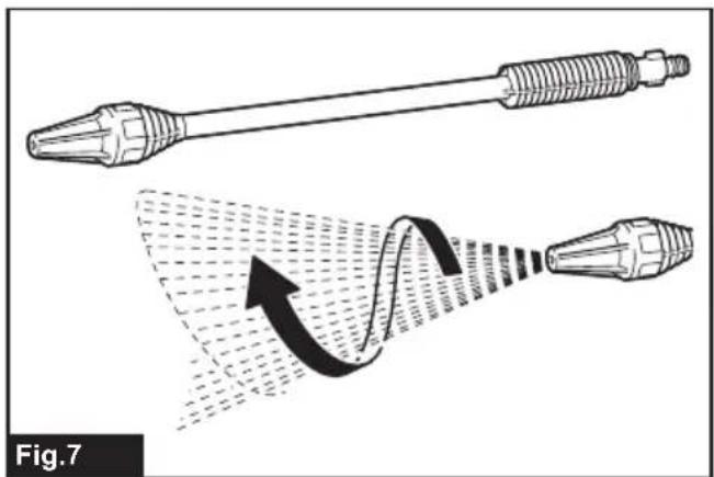
Cyclone jet nozzle
Country specific
NOTICE: Do not use the cyclone jet nozzle to clean fragile surfaces such as windows or car bodies.
▶ Fig.7
A spiral jet is ejected. Suitable for removing stubborn dirt.
Vario spray nozzle and extension
Country specific
⚠️CAUTION: Install only the vario spray nozzle to the extension. Do not connect the other optional extensions to the original extension.
Using any attachments other than those recommended by the manufacturer may cause a risk of damage or injury to persons.
⚠️CAUTION: When adjusting the jet pressure, do not rotate the nozzle while pulling it toward the trigger gun. The nozzle may come off from the trigger gun and cause a personal injury.
⚠️CAUTION: When rotating the tip of the nozzle to adjust the water jet, do not rotate it forcibly.
Otherwise, the nozzle may break and cause an injury
▶ Fig.8: 1. Vario spray nozzle 2. Extension Jet pressure can be adjusted by rotating the nozzle.
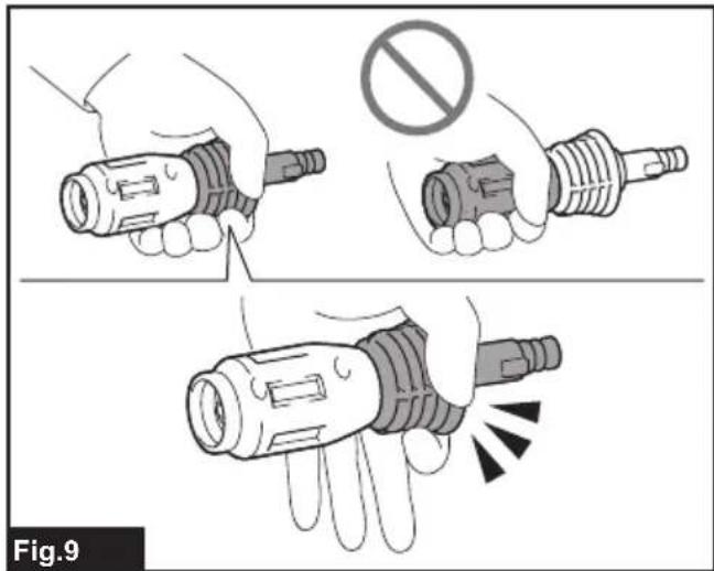
NOTICE: When turning the nozzle, do not hold the tip of the nozzle, but hold the root of the nozzle as shown in the figure.
▶ Fig.9
NOTE: The vario spray nozzle can also be directly attached to the trigger gun.
Trigger operation
NOTICE: To avoid mechanical error in the pressure switch, always leave a two-second interval between trigger operations.
Pull the trigger to eject a water jet. The jet continues as long as the trigger is squeezed. The trigger can be locked for safe handling of the trigger gun. To lock the trigger, pull out the stopper and hook it to the groove on the grip.
▶ Fig.10: 1. Trigger 2. Stopper 3. Groove
ASSEMBLY
⚠ WARNING: Always be sure that all the battery cartridges are removed before carrying out any work on the machine. Failure to remove all the battery cartridges may result in serious personal injury from accidental start-up.
Connecting the high-pressure hose
⚠️CAUTION: Make sure that the high-pressure hose is securely connected. A loose connection may blow the high-pressure hose off, resulting in a personal injury.
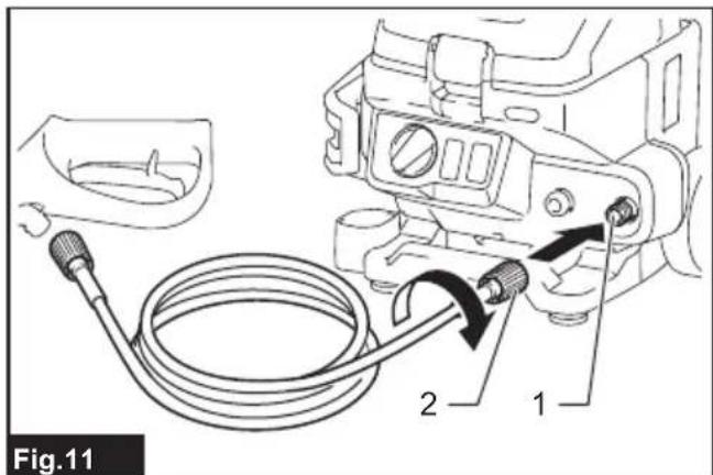
Connect the high-pressure hose to the outlet. Turn the nut on the high-pressure hose clockwise while screwing it onto the screw thread of the outlet.
▶ Fig.11: 1. Outlet 2. Nut
Attaching the trigger gun
CAUTION: Make sure that the high-pressure hose is securely connected. A loose connection may blow the high-pressure hose off, resulting in a personal injury.
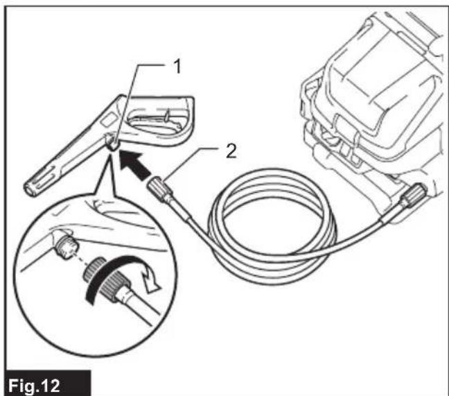
Connect the high-pressure hose to the inlet on the trigger gun. Turn the nut on the high-pressure hose clockwise while screwing it onto the screw thread on the inlet.
▶ Fig.12: 1. Inlet 2. Nut
Connecting to a faucet
CAUTION: Always use a pressure-resistant water hose with the following diameters and connect to the faucet using a proper fittings. Otherwise, the water hose and/or the fitting may break and cause personal injury.
• Inner diameter of hose is 14 mm to 15 mm.
- Outer diameter of hose is 20 mm or less.
- Thickness of hose is 2.3 mm or more and less than 3.0 mm.
NOTICE: Use a pressure-resistant water hose as short as possible. The amount of intake water should be higher than the max feed volume of the pump.
NOTICE: If you connect to the mains for drinking water, use a backflow preventer valve which meets the regulations in your region.
NOTICE: When connecting to a faucet, the required water flow rate is 7.0 L/min or more. If the water flow rate is insufficient, you cannot obtain the full capability of the machine.
NOTE: The hose assembly ships with coupling sleeves attached to both ends. When connecting to a faucet without a coupling sleeve, remove the coupling sleeve at one end by turning the coupling sleeve in the direction of the arrow shown in the figure.
▶ Fig.13: 1. Nut of the coupling sleeve 2. Coupling sleeve
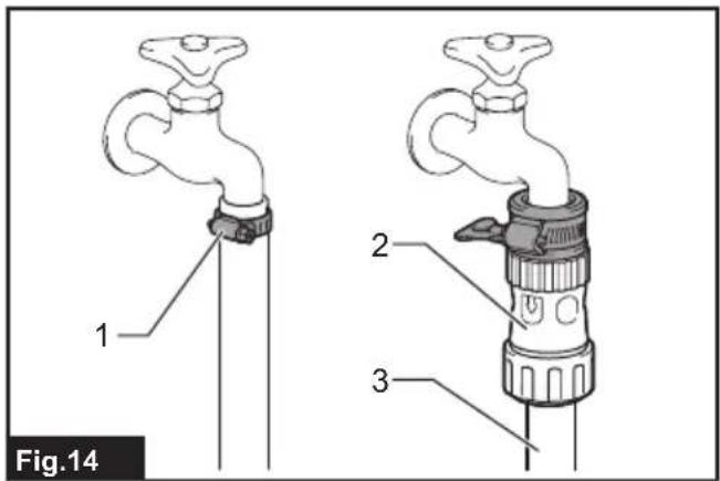
- Connect the hose assembly to the faucet. Apply a suitable fitting such as hose band or water tap joint to secure the hose end with the faucet.
▶ Fig.14: 1. Hose band 2. Coupling sleeve 3. Hose assembly
NOTICE: Connect the hose assembly to the faucet securely. Otherwise, the hose assembly may come off when you open the faucet.
NOTE: The fitting depends on the shape of the faucet to which you connect. Prepare a suitable commercially-bought fitting.
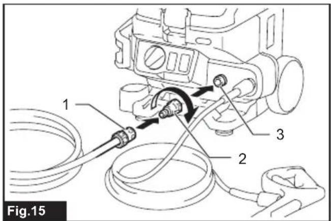
- Attach the water hose connector to the inlet, and then attach the coupling sleeve to the water hose connector.
▶ Fig.15: 1. Coupling sleeve 2. Water hose connector 3. Inlet
NOTICE: When attaching the water hose connector and coupling sleeve, attach them securely.
Otherwise, the water hose connector or coupling sleeve may come off when you open the faucet.
Connecting/disconnecting the nozzle
⚠️CAUTION: Always lock the trigger of the trigger gun when connecting/disconnecting the nozzle.
⚠CAUTION: When connecting the nozzle to the trigger gun, connect it securely and make sure that it does not come off.
CAUTION: When connecting or disconnecting the nozzle, do not rotate it forcibly. Otherwise, the nozzle may break or come off and cause an injury.
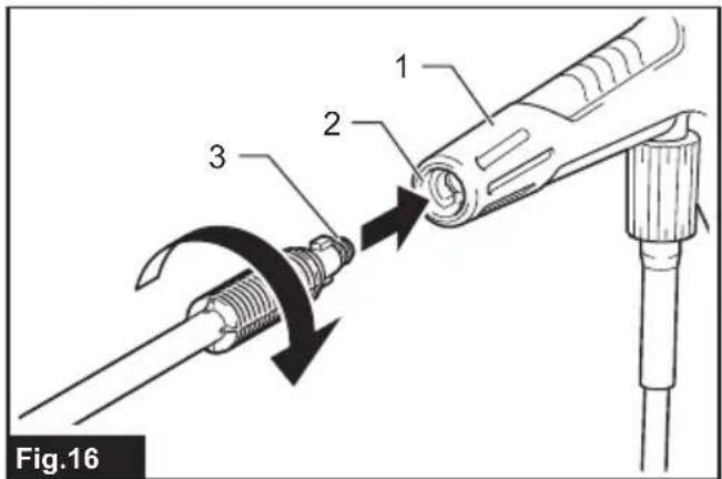
Insert the end of the nozzle into the slot on the trigger gun, and turn it in the direction of the arrow as shown in the figure while pressing the nozzle toward the trigger gun. To disconnect the nozzle, turn the nozzle in the reverse direction while pressing it toward the trigger gun, and then pull it out.
▶ Fig.16: 1. Trigger gun 2. Slot 3. End of the nozzle
Connecting the foam nozzle
Optional accessory
⚠️CAUTION: Always lock the trigger of the trigger gun when connecting/disconnecting the nozzle.
NOTICE: Use only neutral detergents. Do not use household detergents, acid detergents, alkaline detergents, bleaches, solvents, flammable material, or industrial grade solutions, which may damage the machine or your property. Prepare cleaning solution as instructed on the solution bottle, and always test it in an inconspicuous place in advance.
NOTICE: If a highly viscous detergent is used, the nozzle is likely to clog. When using the high viscosity detergent, dilute the detergent by adding water to the bottle before use.
NOTE: When using the foam nozzle, the detergent in the bottle is diluted with the water supplied by the machine and sprayed. You do not have to dilute the concentration of detergent in the bottle more than necessary. Adjust the concentration of detergent while checking the usage conditions.
NOTE: If the foam nozzle is tipped on its side, the detergent may spill.
Prepare detergent before using the foam nozzle.
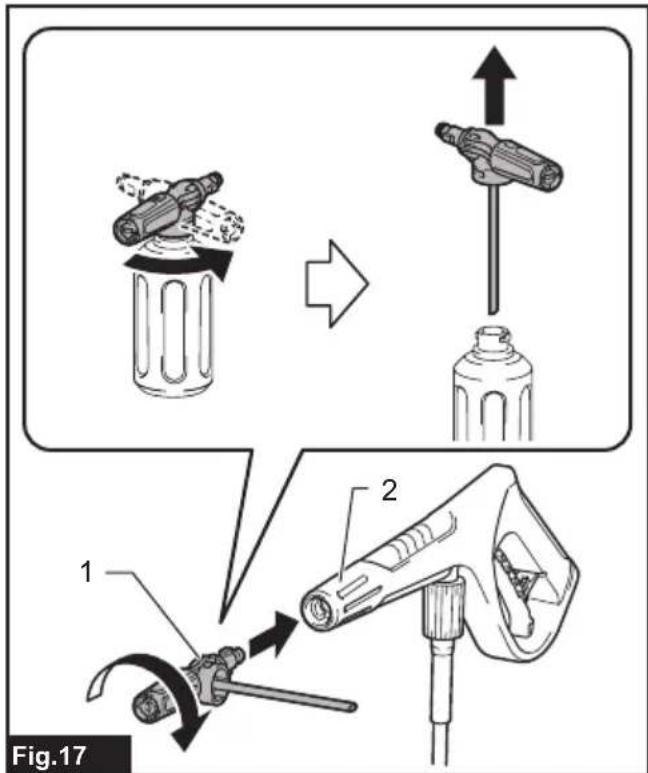
- Remove the nozzle from the tank by rotating the nozzle counterclockwise. Attach the nozzle to the trigger gun.
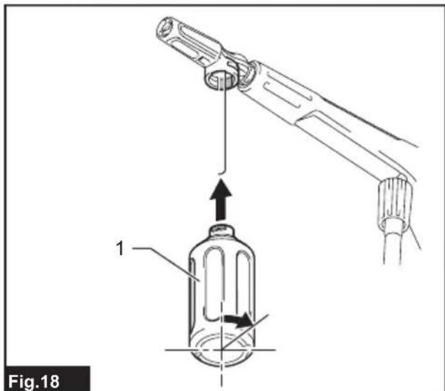
▶ Fig.17: 1. Nozzle 2. Trigger gun - Pour the detergent into the tank, and attach the tank to the nozzle by turning it in the direction shown in the figure.
▶ Fig.18: 1. Tank
OPERATION
WARNING: Do not touch the water jet or direct it toward yourself or others. The water jet is dangerous and can hurt you or others.
WARNING: When shooting the water jet, never hold the object that you are cleaning or place your hands and feet near the water jet.
CAUTION: Stay alert to the rebound of the water jet and blown objects. Do not bring the nozzle to the object closer to 30 cm.
CAUTION: Do not run the high pressure washer without water for longer than 1 minute.
⚠️ CAUTION: Do not operate the high pressure washer for an extended period of time. This may cause overheating or fire. Also, long-term use may cause vibration disorder.
CAUTION: Be aware of the direction of the wind. If the detergent gets into your eyes or mouth, rinse with fresh water immediately and seek medical attention if necessary.
CAUTION: Hold the trigger gun firmly. The trigger gun recoils when you pull the trigger.
CAUTION: Always hold the trigger gun by the grip and barrel when ejecting water jet.
NOTICE: Avoid using the high pressure washer for longer than 1 hour. After using it for 1 hour, leave a same length of intermission.
NOTICE: To protect the mechanism of the high pressure washer, do not use water hotter than 40^ C.
NOTICE: Be careful not to pull the trigger gun forcibly during operation. It may cause the high pressure washer to fall over.
NOTICE: When suspending the operation for a long time, switch off the high pressure washer and squeeze the trigger to discharge the remaining water fully.
If the high pressure washer is left for a long time while maintaining high pressure, it may not restart. In this situation, switch off the high pressure washer, supply water from a faucet to the inlet and squeeze the trigger with keeping the water supply for a while. And then, switch on the high pressure washer.
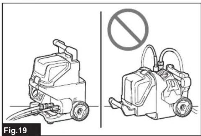
NOTICE: Do not use the machine in an overturned position. Doing so may cause malfunction.
▶ Fig.19
Before operating the machine, remove the nozzle from the trigger gun.
- Open the battery cover and install the battery cartridges into the high pressure washer and then lock the battery cover.
▶ Fig.20: 1. Battery cartridge 2. Battery cover -
Connect one end of the high-pressure hose to the trigger gun and the other end to the high pressure washer.
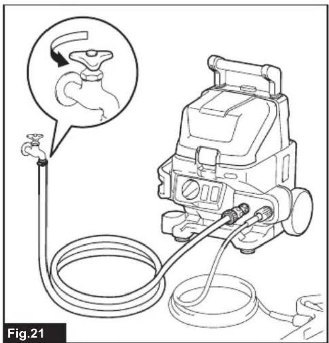
-
Connect the high pressure washer and the faucet using a water hose. After that, open the faucet.
▶ Fig.21
NOTICE: Before turning on the machine, make sure that the faucet is fully open.
- Select the desired mode by pressing the mode switching button, and then turn the power switch clockwise to turn on the machine.
▶ Fig.22: 1. Power switch 2. Mode switching button
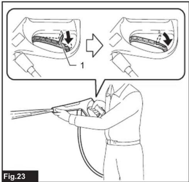
- To eject a water jet, unlock the stopper and squeeze the trigger. Once water is ejected stably from the trigger gun, release the trigger and turn the machine off.
▶ Fig.23: 1. Stopper
NOTE: Be sure to remove the nozzle from the trigger gun before performing this operation.
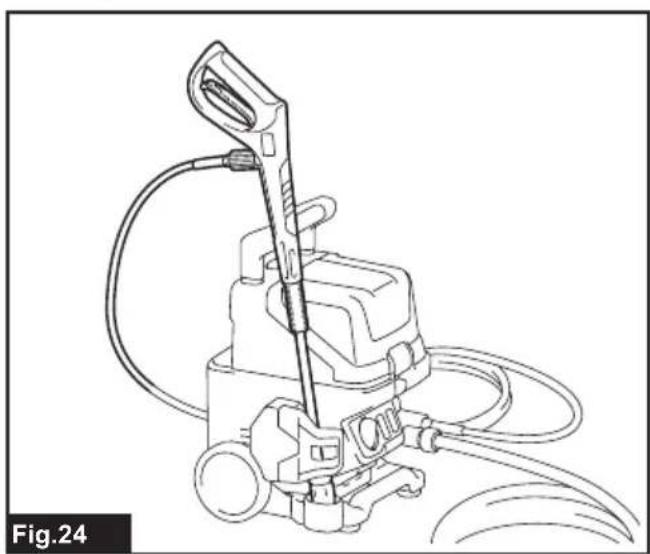
- Attach the nozzle to the trigger gun for your purpose, and then turn on the machine to start the washing operation.
When you suspend the operation, you can temporarily place the trigger gun as shown in the figure.
▶ Fig.24
Supplying water from a tank/reservoir
⚠️CAUTION: When attaching the sleeve to the filter case of the strainer assembly, be careful not to hurt your hand by the hose band.
NOTICE: Always use Makita's hose assembly and strainer assembly.
NOTICE: Always keep 1.0 m or less in height between the inlet of the high pressure washer and the water surface. Otherwise, the high pressure washer will be unable to take the water up into the pump.
NOTICE: The water level that the machine can pump up is 100 mm or more.
NOTICE: Do not use water from rivers, ponds, or water mixed with sand or mud. Doing so may cause malfunction.
NOTE: If it takes a long time for the water to come out, clean the strainer and the filter of the strainer assembly.
You can supply water from a tank or reservoir instead of a faucet.
-
Turn off the machine, and remove the nozzle from the trigger gun.
-
Connect the hose assembly and strainer assembly to the water hose connector.
▶ Fig.25: 1. Tank/reservoir 2. Strainer assembly 3. Hose assembly 4. Water hose connector
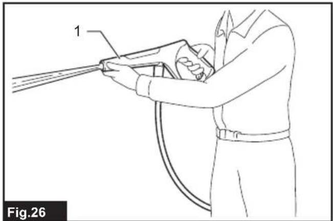
- Turn on the machine, and unlock the stopper and squeeze the trigger. Once water is ejected stably from the trigger gun, release the trigger.
▶ Fig.26: 1. Trigger gun
NOTE: It takes about 10 to 60 seconds for the water to come out.
NOTE: Be sure to remove the nozzle from the trigger gun before performing this operation.
- Turn off the machine and attach the nozzle to the trigger gun for your purpose, and then turn on the machine to start the washing operation.
NOTE: When water is not ejected, detach the hose assembly and strainer assembly and soak them in water. Then reconnect them to the machine.
▶ Fig.27: 1. Hose assembly and strainer assembly
NOTE: If water suction does not work, it takes a long time, or the water pressure is not enough, check the following:
- Loosening of the hose assembly, strainer assembly, and water hose connector.
- Coupling sleeves of the hose assembly are firmly attached onto the water hose connector and filter case of the strainer assembly.
Tighten if they are loose.
Hose assembly
▶ Fig.28: 1. Coupling sleeve
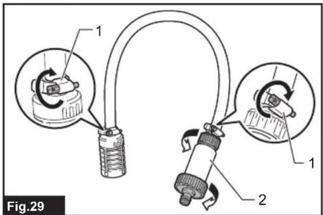
Strainer assembly
▶ Fig.29: 1. Hose band 2. Filter case
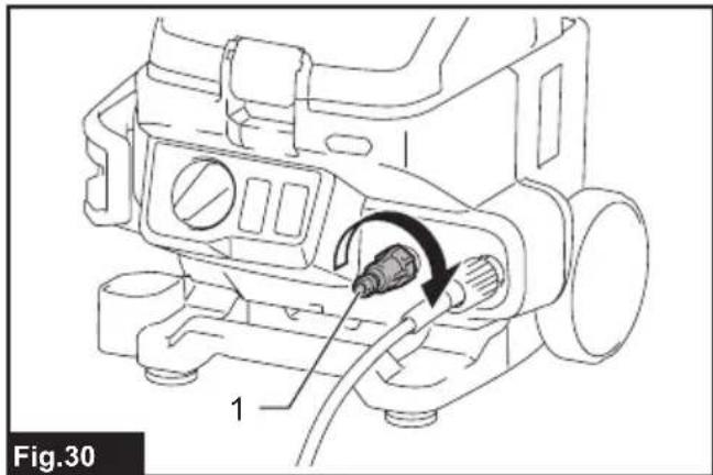
Water hose connector
▶ Fig.30: 1. Water hose connector
After use
CAUTION: After operating the high pressure washer, always perform the procedure described in this manual. Residual pressure in the trigger gun or high pressure washer can cause personal injury or damage to the pump inside.
- Turn off the machine, and remove the nozzle from the trigger gun.
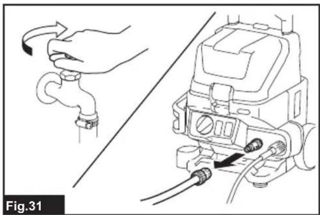
- Close the faucet and disconnect the water hose from the high pressure washer.
▶ Fig.31 - Switch on the high pressure washer again.
- Squeeze the trigger until the remaining water in the high pressure washer is discharged.
▶ Fig.32
NOTICE: Do not run the motor for longer than 1 minute.
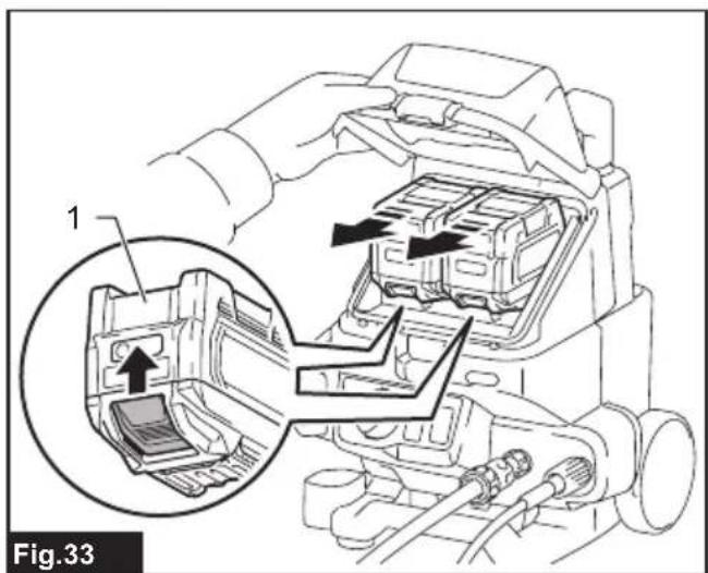
- Switch off the high pressure washer and remove the battery cartridges.
▶ Fig.33: 1. Battery cartridge - Disconnect the high-pressure hose from the trigger gun and the high pressure washer.
▶ Fig.34: 1. Trigger gun 2. High-pressure hose
NOTICE: To prevent the high-pressure hose from being damaged, drain the remaining water in the hose before storing.
- Hold the machine with both hands, and drain the remaining water inside of the machine by tilting the machine as shown in the figure.
▶ Fig.35
WARNING: Always be sure that all the battery cartridges are removed from the machine before storing or carrying the machine or attempting to perform inspection or maintenance.
NOTICE: Never use gasoline, benzine, thinner, alcohol or the like. Discoloration, deformation or cracks may result.
To maintain product SAFETY and RELIABILITY, repairs, any other maintenance or adjustment should be performed by Makita Authorized or Factory Service Centers, always using Makita replacement parts.
Carrying the machine
⚠️CAUTION: Before carrying the machine with both hands, make sure that the handle is folded completely.
When carrying the machine, hold the machine firmly with both hands by holding the handle with one hand and the bottom grip with the other hand.
▶ Fig.36: 1. Handle 2. Bottom grip
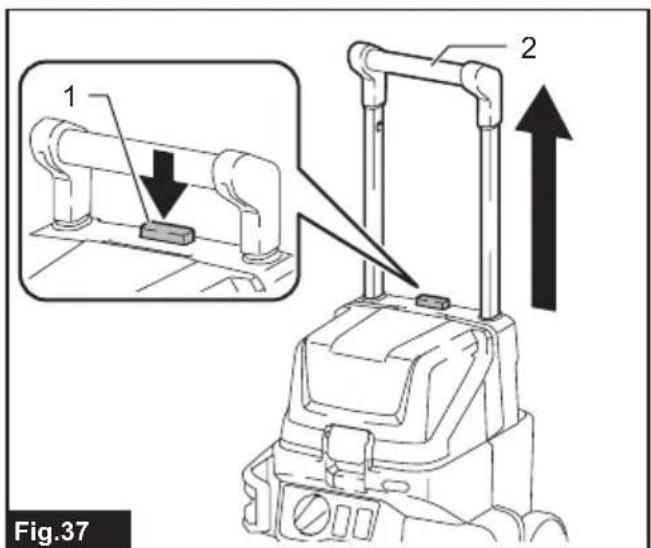
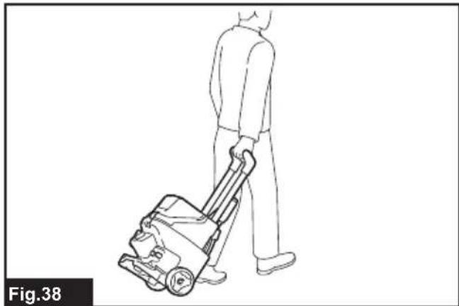
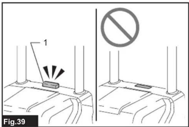
You can also carry the machine using the wheels of machine. Be sure to extend the handle by pressing the lock-off button before carrying the machine.
▶ Fig.37: 1. Lock-off button 2. Handle
▶ Fig.38
⚠️CAUTION: Do not apply excessive force by leaning on the extended handle. If the handle comes off, you may fall over and be injured.
NOTICE: Make sure that the handle is fully extended and the lock-off button is returned to its original position before carrying the machine.
▶ Fig.39: 1. Lock-off button
Cleaning the nozzle
NOTICE: Do not remove dirt or debris forcibly. This may result in personal injury or damage to the ejection hole causing deviated jet angles or poor performance.
Use the cleaner pin to remove dirt from or unclog the nozzle.
▶ Fig.40: 1. Cleaner pin
NOTE: To maintain the optimal performance, clean the nozzle periodically.
Cleaning the filter
Detach the water hose connector and remove dirt and debris from the inside of the filter.
▶ Fig.41: 1. Water hose connector 2. Filter 3. Sealing ring
When using the strainer assembly, take the filter out of the filter case and remove dirt and debris.
▶ Fig.42: 1. Filter 2. Filter case
NOTE: To maintain the optimal performance, clean the filter periodically.
Storage
NOTICE: Always store in an indoor location where the temperature does not go below freezing. If the high pressure washer freezes and malfunctions, contact your local service center for repairs.
NOTICE: Be sure to drain the water inside the machine completely before storing the machine. Malfunctions or damage caused by freezing due to inadequate draining are subject to be not covered by warranty.
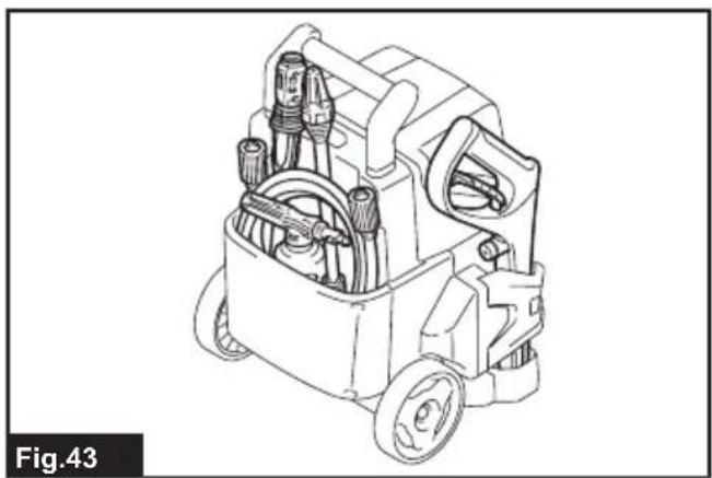
Store the accessories in the pocket at the rear of the machine.
▶ Fig.43
TROUBLESHOOTING
Before asking for repairs, conduct your own inspection first. If you find a problem that is not explained in the manual, do not attempt to disassemble the machine. Instead, ask Makita Authorized Service Centers, always using Makita replacement parts for repairs.
| State of abnormality Probable cause | (malfunction) Remedy | |
| The washer does not start. No electricity install charged battery cartridges, and turn on the power switch. | ||
| No water jet / weak water jet No water supply or poor water supply Make sure that the faucet is open. If using the hose assembly and strainer assembly, introduce water into the hose. | ||
OPTIONAL ACCESSORIES
CAUTION: These accessories or attachments are recommended for use with your Makita machine specified in this manual. The use of any other accessories or attachments might present a risk of injury to persons. Only use accessory or attachment for its stated purpose.
If you need any assistance for more details regarding these accessories, ask your local Makita Service Center.
- Nozzles and hoses
• Makita genuine battery and charger
NOTE: Some items in the list may be included in the product package as standard accessories. They may differ from country to country.
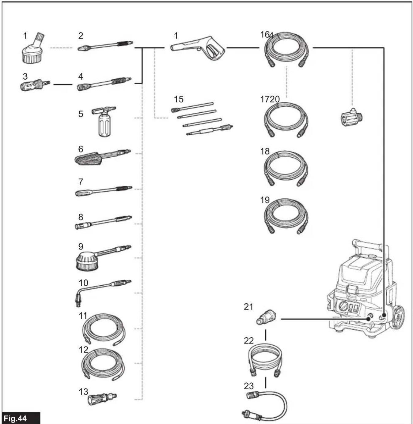
Combinations of nozzles and hoses
▶ Fig.44
| 1 | Splash guard | 2 | Cyclone jet nozzle *1 | 3 | Vario spray nozzle *1 |
| 4 | Extension *1 | 5 | Foam nozzle | 6 | Wash brush |
| 7 | Vario spray lance | 8 | Variable nozzle | 9 | Rotating brush |
| 10 | Under body spray lance | 11 | Pipe cleaning hose (10 m) | 12 | Pipe cleaning hose (15 m) |
| 13 | Connecting joint | 14 | Trigger gun *1 | 15 | Lance extension *2 |
| 16 | High-pressure hose *1 | 17 | Extension high-pressure hose (5 m) | 18 | Extension high-pressure hose (8 m) |
| 19 | Extension high-pressure hose (10 m) | 20 | Swivel joint | 21 | Water hose connector *1 |
| 22 | Hose assembly *1 | 23 | Strainer assembly *1 | - | - |
*1: Standard accessory
*2: Not available in combination with under body spray lance.
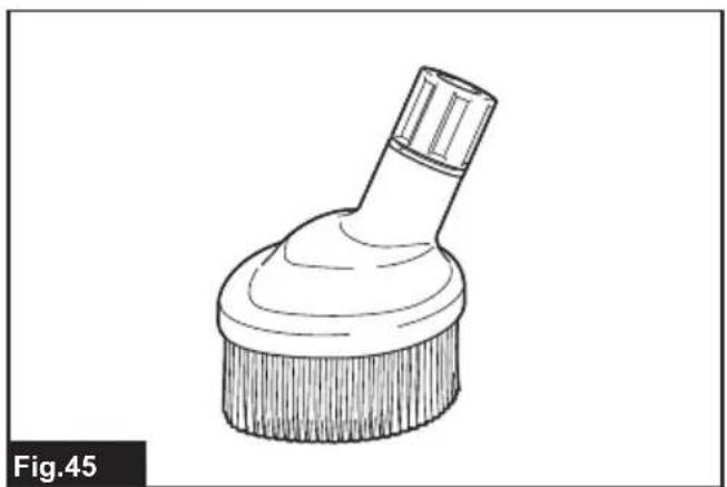
Splash guard
▶ Fig.45
Reduces splash back when cleaning corners with the cyclone jet nozzle.
▶ Fig.46: 1. Nut 2. Cyclone jet nozzle
When using the splash guard, remove the nut from the splash guard, then insert the cyclone jet nozzle into the splash guard, and then tighten the nut.
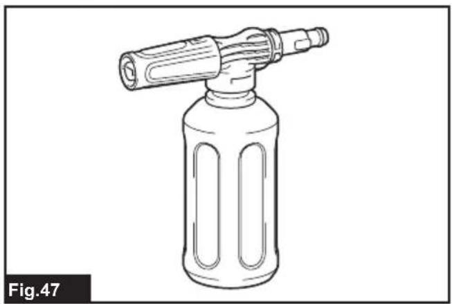
Foam nozzle
▶ Fig.47
Detergent can be sprayed as foam.
Wash brush
▶ Fig.48
A nozzle equipped with a brush. Useful for washing out dirt while scrubbing with brush.
Vario spray lance
⚠️CAUTION: When adjusting the jet pressure, do not rotate the nozzle while pulling it toward the trigger gun. The nozzle may come off from the trigger gun and cause a personal injury.
⚠️CAUTION: When rotating the tip of the nozzle to adjust the water jet, do not rotate it forcibly. Otherwise, the nozzle may break and cause an injury.
▶ Fig.49
Jet pressure can be adjusted by rotating the nozzle.
Variable nozzle
⚠️CAUTION: When adjusting the jet width, do not rotate the nozzle while pulling it toward the trigger gun. The nozzle may come off from the trigger gun and cause a personal injury.
⚠CAUTION: When rotating the tip of the nozzle to adjust the water jet, do not rotate it forcibly. Otherwise, the nozzle may break and cause an injury.
▶ Fig.50
Jet width can be adjusted from 0^ to 25^ by rotating the front end of the nozzle.
Rotating brush
▶ Fig.51
Three brushes inside rotate slowly when ejecting the jet. Suitable for cleaning light dirt on an exterior wall, car body, bath tub, etc.
Under body spray lance
⚠️ CAUTION: Do not use the under body spray lance with the lance extension.
▶ Fig.52
An extra long spray lance with angled nozzle. Best for cleaning hard-to-reach areas such as car under body and roof gutter.
Pipe cleaning hose (10 m/15 m)
CAUTION: Pay particular attention to the water jet when using the pipe cleaning hose. Highly intense water jet is ejected backward. Only trigger the water jet when the nozzle has been inserted into the pipe to be cleaned at least up to the red marking.
▶ Fig.53
For cleaning and unclogging plumbing and downpipes.
Connecting joint
▶ Fig.54
A joint to connect with a nozzle from other model.
Some optional nozzles require the connecting joint (optional accessory) to attach to the trigger gun. Attach the connecting joint to the trigger gun in the same way as the nozzle.
▶ Fig.55: 1. Nozzle 2. Connecting joint 3. Trigger gun
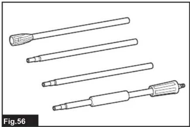
Lance extension
▶ Fig.56
Pipes to extend the length of the trigger gun. Three different lengths are available by changing the number of the pipes to be used.
Extension high-pressure hose (5 m/8 m/10 m)
▶ Fig.57
Extension hose to connect the high pressure washer body with the trigger gun.
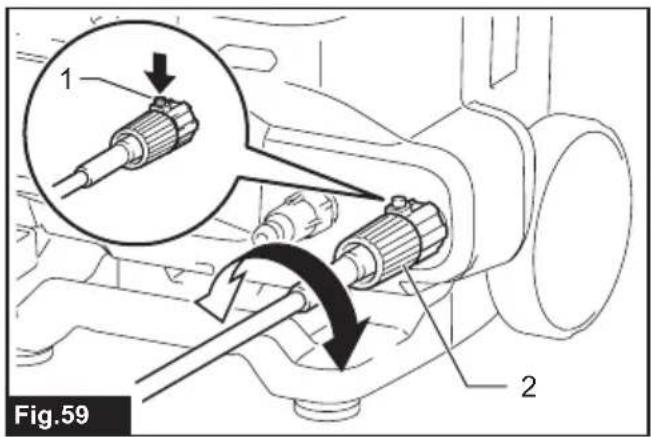
Swivel joint
▶ Fig.58
Prevents the high-pressure hose from being twisted.
▶ Fig.59: 1. Button 2. Nut
To connect or disconnect the high-pressure hose to or from the swivel joint, turn the nut on the high-pressure hose while pressing the button on the swivel joint.
Hose assembly
▶ Fig.60
A hose assembly to connect a faucet to the product, or the strainer assembly to the product.
Strainer assembly
▶ Fig.61
A strainer assembly to supply water from a tank or reservoir. Use the hose assembly to connect to the product.
AVERTISSEMENT
▶ Fig.46: 1. Écrou 2. Gicleur cyclone
⚠ WAARSCHUWING: Draag gehoorbescherming.
VEILIGHEIDSWAAR- SCHUWINGEN
BELANGRIJKE VEILIGHEIDSWAARSCHUWINGEN
▶ Fig.36: 1. Handgreep 2. Ondergreep
OPTIONELE ACCESSOIRES
▶ Fig.59: 1. Knop 2. Moer
▶ Fig.28: 1. Koblingsmuffe
Simontering
▶ Fig.40: 1. Rensepind
