C.A 6710 - Measuring equipment CHAUVIN ARNOUX - Free user manual and instructions
Find the device manual for free C.A 6710 CHAUVIN ARNOUX in PDF.


User questions about C.A 6710 CHAUVIN ARNOUX
0 question about this device. Answer the ones you know or ask your own.
Ask a new question about this device
Download the instructions for your Measuring equipment in PDF format for free! Find your manual C.A 6710 - CHAUVIN ARNOUX and take your electronic device back in hand. On this page are published all the documents necessary for the use of your device. C.A 6710 by CHAUVIN ARNOUX.
USER MANUAL C.A 6710 CHAUVIN ARNOUX
natural_image
Open white plastic medical or electrical testing kit with various electronic components and wiring (no visible text or labels)FRANÇAIS
ENGLISH
text_image
J ON W F T E ES CEFigure 7
Meaning of the symbol ⚠:
Warning! Please refer to the user's manual before using the instrument.
In this User's Manual, the instructions preceded by the above symbol, should they not be carried out as shown, can result in a physical accident or damage the instrument and the installations.
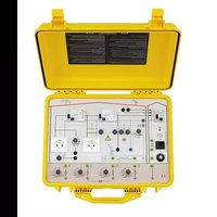
Thank you for purchasing this C.A. 6710 "Electrical Installation" demo case.
To obtain the best possible service from your instrument:
■Read these operating instructions carefully,
■Comply with the precautions for use.
■This demo case can only be used with the following measuring instruments:
- C.A 6115N (multi-function installation tester),
- C.A 6421/23/25 (earth testers),
- C.A 6511/13 or C.A 6521/23/25/31/33 (insulation testers),
- MX4600/ CDA 10 (differential testers).
PRECAUTIONS FOR USE
■ The demo case can only operate correctly if the polarity of the network to which it is connected is correct.
For this demo case to operate correctly, it must also be connected to a network with the correct earth resistance (< 50 Ω).
An acoustic and visual test enables the connection to the earth of the network and to the earth of the case to be checked along with the polarity of the network.
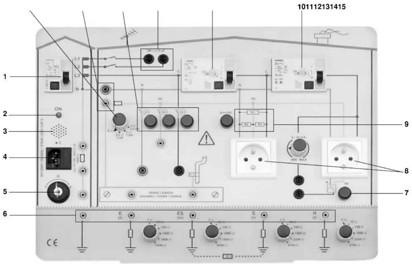
■Before using the demo case, see figure 1:
- Check that the differential system on the case's input (ref. 1) is set to position O
- Set the power on switch and phase-neutral inverter (ref. 5) to 0.
- Connect the demo case to the network using the power cable
■ To check the operation of the buzzer, the red polarity LED or the fuse beforehand, perform the following tests:
- Set the power on switch to position 1 and note the status of the buzzer and the red LED.
-
Set the power on switch to position 2 and note the status of the buzzer and the red LED.
-
If the buzzer is triggered and the red LED comes on in positions 1 and 2, it means that the network earth and the case earth have not yet been connected. DO NOT USE THE CASE and check the continuity between the network earth and the case earth. If the continuity is correct, RETURN TO THE AFTER-SALES DEPARTMENT.
- If the buzzer is not triggered in position 1 or position 2, it is not working. RETURN TO THE AFTER-SALES DEPARTMENT.
- If neither the buzzer nor the red LED are activated in position 1 or position 2, the fuse must be changed. Use the spare fuse next to the blown fuse installed, both located in the power socket (ref. 4). If the buzzer and the LED still do not work, RETURN TO THE AFTER-SALES DEPARTMENT.
- If all the tests above prove satisfactory (connection to network earth correct – buzzer in working order – red LED in working order – fuse operational), set up the following configuration:
where the buzzer does not sound
and the red LED comes on.
- If and only if the connection is correct, set the input differential system (ref. 1) to the position I.
■ This demo case has been designed to demonstrate measuring instruments on different types of electrical installations.
Any other use will automatically cancel the warranty and discharge the manufacturer from any liability in the event of a problem.

Do not create any phase / neutral or phase / earth short circuits. Such faults can damage the case and trip the protective systems of the installation to which the case is connected.
Apart from on the socket for connection to the mains, all the earths on the case (including those on the sockets) are «simulated» earths which are not really connected to the earth.
Do not apply voltages on the earth simulation terminals.
CONTENTS
- PRESENTATION 2
- DESCRIPTION 3
- NEUTRAL SYSTEMS 4
3.1 TT network 4
3.2 TN network 5
3.3 IT network 5
- INSULATION RESISTANCE MEASUREMENT 6
4.1 Case 1: Measurement of insulation with a 2 MΩ resistance in parallel with a capacity of 5 μF (configuration of insulation measurement between conductors)....6
4.2 Case 2: Insulation measurement in a single-phase mains socket (configuration for measurement of the insulation of the whole installation in relation to the earth)....6
-
CHECKING OF DIFFERENTIAL DEVICE 7
-
EARTH AND RESISTIVITY MEASUREMENT 8
6.1 Resistivity measurement 8
6.2 Earth measurement 8
- LOOP MEASUREMENT 9
- CONTINUITY MEASUREMENT 10
-
FAULT SIMULATION 11
-
TECHNICAL SPECIFICATIONS.... 12
10.1 Electrical 12
10.2 Dimensions and weight 12
10.3 Power supply 12
10.4 Environmental conditions 12
10.5 Compliance with standards 12
- MAINTENANCE 13
11.1 Cleaning 13
11.2 Calibration testing 13
-
WARRANTY 13
-
TO ORDER 13
1. PRESENTATION
The «Electrical Installation» demo case can be used to simulate the different types of neutral systems characteristic of the electrical systems encountered in domestic, tertiary and industrial environments:
■ TT system
■ TN-S or TN-C system
■ IT system
Depending on the measuring instruments used with this demo case, it is possible to measure:
■ Earth / Resistivity
■ Differential systems
■ Insulation
■ Phase-neutral or phase-earth loop
■ Continuity
For each neutral system, certain faults can be simulated:
■ Phase outage
■ Neutral cut-off
■ Earth cut-off
■ Neutral-earth inversion
■ Phase-earth leakage current (4...34 mA)
In its robust site casing suitable for all conditions in the field, it is easy to transport from one place to another thanks to its fold-away handle.
A depressurization valve (unscrewable black button near the handle or two holes under the handle, depending on the series) also allows you to take it on aircraft without worrying about opening the case when you arrive, despite the wide pressure variations.
2. DESCRIPTION
text_image
101112131415 1 2 3 4 5 6 E (+) ES (+) S (+) H (+) 9 8 7 101112131415 ENPOPRO / TURNO / LUNNAFigure 1
1 Type-A differential protection system (10 mA).
2 Red polarity LED.
3 Phase-neutral inversion buzzer
4 230 V - 50 Hz power socket (with accessible fuse and spare fuse)
5 Power on switch and phase-neutral inverter
6 Internal earth sockets for simulation of the different neutral systems and earth or resistivity measurement (Caution: sockets not connected to the earth of the installation)
7 Pushbutton for creating a phase-neutral or phase-earth leakage current between 4 and 34 mA
8 2 mains sockets (2P+E)
9 3 insulating resistances between phase, neutral and earth
10 30 mA differential, type A,
11 300 mA differential, type A, selective
12 2 MΩ resistance in parallel with a capacity of 5 μF for insulation impedance simulation
13 Possible cut-off of the phase, neutral or PE
14 Neutral-earth connection terminals (TN system)
15 Resistances in series with an inductance to vary the impedance of the PE conductor
3. NEUTRAL SYSTEMS
text_image
A B C D T E ES F ON L1 L2 L3 N 1000Ω/100Ω CFS 100Ω 30Ω 10Ω 50Ω 10Ω 10Ω 10Ω 10Ω 10Ω 10Ω 10Ω 10Ω 10Ω 10Ω 10Ω 10Ω 10Ω 10Ω 10Ω 10Ω 10Ω 10Ω 10Ω 10Ω 10Ω 10Ω 10Ω 10Ω 10Ω 10Ω TEURNE / EARTH SPRING / TERRA / TERRA CE E (DC) ES (NC) 1.0V 1.5V 2.0V 2.5V 3.0V 3.5V 4.0V 4.5V 5.0V 5.5V 6.0V 6.5V 7.0V 7.5V 8.0V 8.5V 9.0V 9.5V 10.0V 10.5V 11.0V 11.5V 12.0V 12.5V 13.0V 13.5V 14.0V 14.5V 15.0V 15.5V 16.0V 16.5V 17.0V 17.5V 18.0V 18.5V 19.0V 19.5V 20.0V 20.5V 21.0V 21.5V 22.0V 22.5V 23.0V 23.5V 24.0V 24.5V 25.0V 25.5V 26.0V 26.5V 27.0V 27.5V 28.0V 28.5V 29.0V 29.5V 30.0V 30.5V 31.0V 31.5V 32.0V 32.5V 33.0V 33.5V 34.0V 34.5V 35.0V 35.5V 36.0V 36.5V 37.0V 37.5V 38.0V 38.5V 39.0V 39.5V 40.0V 40.5V 41.0V 41.5V 42.0V 42.5V 43.0V 43.5V 44.0V 44.5V 45.0V 45.5V 46.0V 46.5V 47.0V 47.5V 48.0V 48.5V 49.0V 49.5V 50.0VFigure 2
IMPORTANT PRECAUTION:
This demo case has been designed to simulate measurement on various types of electrical networks. It has not been designed to recreate the electrical faults which may occur on these networks. Do not create short circuits between the phase, neutral and earth.
3.1 TT network
Reminder:
This type of system is used in France, for example, in domestic electrical installation supplied from a public low-voltage distribution network.
In a TT system, the neutral of the public transformer (electricity company) is connected to the ground and the earths of the installation are connected to the ground.
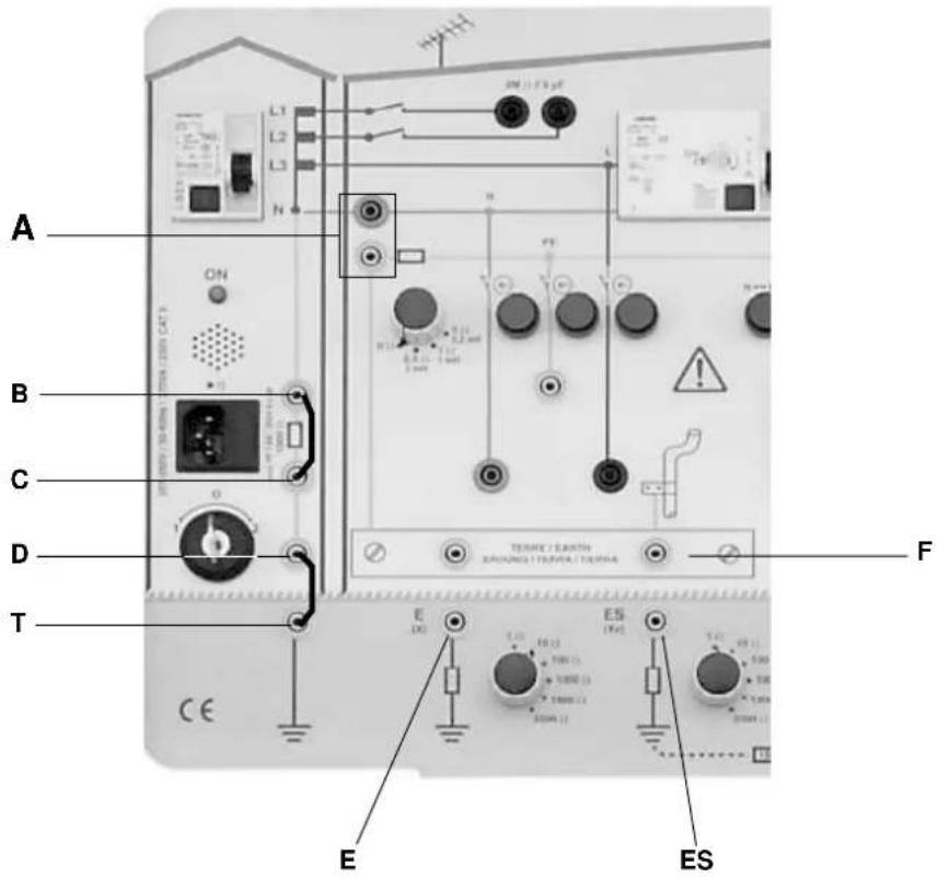
Connections (see figure 2):
■ Do not connect the neutral and the earth at the level of ref. A
■ The 1000 Ω resistance between terminals B and C must be shunted
■ Terminal D must be linked to earth T
■ Earth E must be connected to the earth bar of the building F
■ The ES earth can also be connected to the earth bar F to simulate a complex earth connection made up of earths in parallel.
Theoretical principle:
■ A fault current is closed off by the loop containing the earth connections of the earths and the neutral.
■ A residual differential device (RDD or RCD) cuts off the power when the nominal current of the RDD is reached.
The nominal current must be adapted to the value of Rearth so that Rearth x In < 50 V in dry conditions or 25 V in humid conditions.
■ The earths protected by the same differential or the earths simultaneously accessible must be connected to the same earth.
3.2 TN network
Reminder:
This type of system is used, for example, in tertiary electrical installations powered from a private transformer station.
In a TN system, the neutral of the private transformer is connected to the ground and the earths of the installation are connected to the neutral of this transformer station.
If the neutral conductor is combined with the PE protective conductor, it is a TN-C system.
If these 2 conductors are separate, it is a TN-S system.
Many installations use a TN-C system upstream and a TN-S system downstream (the opposite is prohibited), so that leakage to earth at a specific point can be monitored, for example, because with TN-S it is possible to insert differential devices.
Connections (see figure 2):
■ Connect the neutral and earth terminals at the level of A (if TN-C system)
■ The 1000 Ω resistance between terminals B and C must be shunted
■ Terminal D must be linked to the earth T
- Earths E or ES can also be connected to the earth bar F of the building to ensure that the potential of the conductor serving as PE and N (upstream of A) will remain close to that of the earth despite the neutral current which may pass through it (if a load is connected).
In reality, this causes problems above all when the PE/N conductor is very long, with a resistance significantly different from zero.
Principle:
■ A fault current is closed by the neutral conductor and becomes a phase-neutral short circuit current (with a very high value because the phase-neutral loop has a low impedance).
■ A protective system against excess currents (circuit breakers or fuses) cuts off the installation and protects it.
3.3 IT network
Reminder:
This type of system is used, for example, in industrial electrical installations powered from a private transformer station and operated by qualified personnel.
In an IT system, the neutral of the private transformer is connected with impedance or insulation from the ground and the earths of the installation are connected to the ground.
This is the only system which ensures operating continuity when there is an initial fault, as the installation is only cut off with the second fault.
This is particularly useful in certain sensitive buildings or industries in which the process cannot tolerate interruptions: hospitals, chemicals, glass, oil, metallurgy...
Connections (see figure 2):
■ Do not connect the neutral and the earth at the level of A
■ The 1000 Ω resistance between terminals B and C must not be shunted. In the field, it is sometimes set up in parallel with a capacity.
■ Terminal D must be connected to earth T. In certain practical cases, this connection is not necessary. The transformer is then totally insulated from the earth.
■ Earth E must be connected to the earth bar of the building F
Theoretical principle:
■ The initial fault current is low because it is closed off by the earth of the transformer, which has a high impedance (often 1000 Ω or infinite). The resulting fault voltage on the chassis earth is therefore low and not dangerous.
In the event of a second fault, the current loops via the two faulty loads and protection is provided in the same way as in the TN system: high current cut off by fuses or circuit breakers.
In the field, a Permanent Insulation Controller indicates the occurrence of an initial insulation fault (buzzer + visual indication). This informs the personnel responsible for operation that the first fault has to be repaired before the second cuts off the installation.
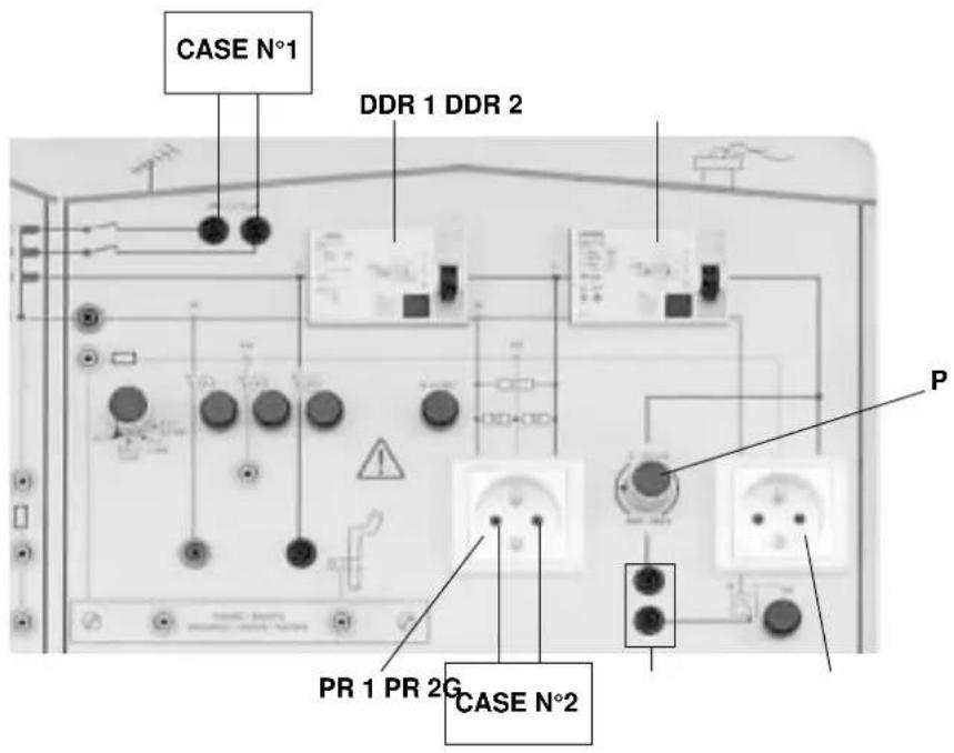
4. INSULATION RESISTANCE MEASUREMENT
text_image
CASE N°1 DDR 1 DDR 2 P PR 1 PR 2G CASE N°2Figure 3
Insulation resistance measurements can be made using the following instruments:
- C.A 6115N
- C.A 6511/13
- C.A 6521/23/25/31/33
4.1 Case 1: Measurement of insulation with a 2 M Ω resistance in parallel with a capacity of 5 μF (configuration of insulation measurement between conductors)
The 2 measurement terminals do not carry any voltage, even if the demo case is powered up and the input differential is set to I.
MEASUREMENT:
■ Connect the leads
- if C.A 6115N: use the cable with 3 separate leads and connect the instrument to the measurement terminals with lead L1/L and lead L2/N connected to lead L3/PE.
- if C.A 6511/13 or C.A 6521/23/25/31/33: use the set of 2 red + black leads with banana plugs on the end.
■ transmit the test voltage (≤ 1000 V DC)

Caution: do not apply a voltage > 1200 V DC
■ and read off the result.
The measurement will take time to stabilize because, at the beginning, the measurement current is only used to charge the 5 F capacity.
This is representative of a measurement on very long cables in a building or on distribution lines, for example. In general, these cables have a significant capacity which influences the insulation measurements.
4.2 Case 2: Insulation measurement in a single-phase mains socket (configuration for measurement of the insulation of the whole installation in relation to the earth)
The two differential devices RDD1 and RDD2 must be set to O.
MEASUREMENT:
Use the same cords as in the previous case, fitted with the test probes at their ends.
Place the test probes between the phase-neutral, phase-earth or neutral-earth terminals of socket P>R1 or PR2 to measure the resistances already placed between these different points in the case and which simulate insulation faults.
Note:
If the C.A 6115N is used, you can also use the measurement cable with mains plug which you can connect directly to the left-hand socket on the case (PR1). Position of the switch on the instrument: R L-N-PE.
With the C.A 6115N, if the RDD2 differential device is not cut off (in position I), the terminals (G) are connected and the leakage current is varied on socket PR2 using the associated potentiometer P, the insulation measured will vary according to the leakage current defined.
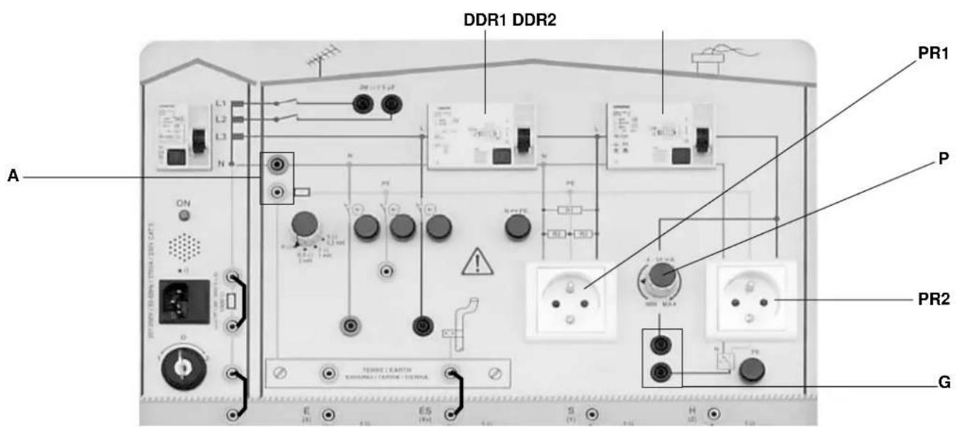
5. CHECKING OF DIFFERENTIAL DEVICE
text_image
DDR1 DDR2 PR1 P PR2 G A ON E ES S H TENRE LEARTH GENERAL CUSTING SYSTEMFigure 4
The differential devices can be checked using the following instruments:
- C.A 6115N
- MX 4600
- CDA 10
The CDA 10 is a tester: it uses LEDs to indicate whether the differential device is operating correctly according to the calibre selected.
It does not allow the following measurements.
Measurements possible with the C.A 6115N and MX 4600:
■ Differential trigger time
■ Measurement of the fault voltage/contact voltage
■ Testing of a selective differential
■ Testing of an AC-type differential (sensitive to AC currents) or type A differential (sensitive to pulsed AC and DC currents)
■ Creation of a leakage current between 4 and 34 mA
MEASUREMENT:
Set to the TT or TN neutral system (see § 3.1 and 3.2).
The two differential devices RDD1 and RDD2 must be set to I.
■ Connect to socket PR1 or PR2.
- if C.A 6115N: use the cable ending in a mains plug to directly connect to the PR1 or PR2 socket.
- if MX 4600: also use the cable ending in a mains plug to directly connect to the PR1 or PR2 socket.
Activate measurement.
The recent measuring instruments enable the differential devices to be discharged before the start of the test (wait for 30 seconds) if they are selective.
They also allow you to choose the starting slope (positive or negative) of the test wave. The differential devices may react differently in these two cases if they were polarized beforehand by leakage currents.
It is possible to vary the earth resistance or PE conductor resistance during the test, which will change the fault voltage measured by the measuring instruments.
If you do not want to pass through the earth resistances, simply connect the A terminals.
Reminder:
Fault voltage = voltage which occurs on the earth when the nominal current of the differential device circulates.
Fault tension = R_earth x In. It must be < 50 V or 25 V (dry or humid conditions).
■ If the G terminals are connected by means of a lead, it is possible to:
- Measure the leakage current created by the potentiometer P using an ammeter or a leakage current clamp, for example.
- Modify the loop for circulation of this leakage current:
- Without doing anything = phase-neutral no triggering
- By pressing the pushbutton located on socket PR2 = phase-earth ➡ triggering
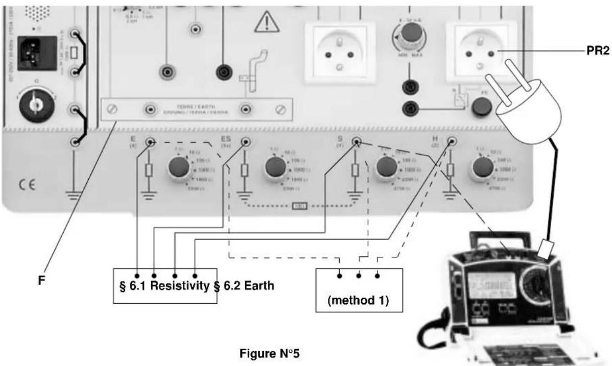
6. EARTH AND RESISTIVITY MEASUREMENT
text_image
PR2 TEWRE / EARTH EXPRESS / TERRA / TEWRE E (V) ES (V) S (V) H (42) F § 6.1 Resistivity § 6.2 Earth (method 1) Figure N°5The earth can be measured using the following instruments:
- C.A 6115N
- C.A 6421/23/25
- MX 4600
Resistivity measurements are only possible with the C.A 6425.
6.1 Resistivity measurement
■ Connect terminals E, ES, S and H (previously X, Xv, Y and Z) of the measuring instrument to the corresponding terminals on the demo case which simulate rods stuck in the ground. These measurement terminals must be disconnected from the earth bar (F) just above.
■ Activate the measurement which must correspond to the 10 Ω resistance R (see drawing above).
The resistivity of a soil in W.m, at a depth of (3/4 of the distance between rods) can then be obtained using the formula:
$$ r = 2 \times p \times \text { distance between rods } (m) \times R $$
(the distance between the rods cannot be simulated)
To simulate difficult measurement conditions, you can vary the resistance of the E, ES, S and H measuring rods.
6.2 Earth measurement
Method 1:
■ Connect terminals E, S and H (previously X, Y and Z) of the measuring instrument to the corresponding terminals on the demo case which simulate rods stuck in the ground. The demo case terminals must be disconnected from the building's earth bar (F).
■ Activate measurement. The value of the earth resistance E of the building can be modified between 1 W and 2200 W using a switch.
The value of the resistance of the auxiliary rods S and H can also be modified to simulate difficult measurement conditions.
Method 2:
Certain multi-function testers offer earth measurement using a slightly different method. This is the case with the C.A 6115N.
The measuring instrument must be connected to the network with the power on via a 2P+E mains socket.
It is then already connected to the earth to measured, E. The instrument must then be connected to an auxiliary rod, S, with the 3rd point H required for correct earth measurement being the earth of the distribution transformer.
So this is a measurement using the «classic principle» (injection of current between E and H, measurement of voltage between E and S, calculation of R) but all you have to do is set up one rod (S) and connect up to a network voltage.
Method 3: MX 4600
- Use the cable fitted with a mains plug to a 2P+E socket on the demo case.
- On the MX 4600, select the nominal sensitivity of the differential device to avoid triggering it.
- Activate measurement and read off the earth resistance result.
text_image
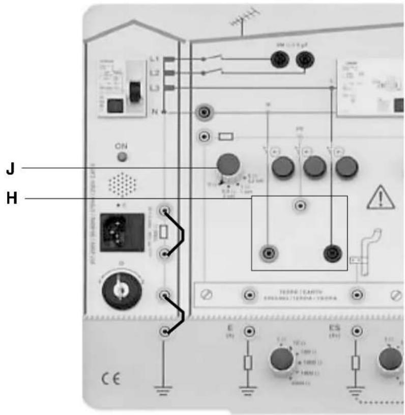
J H CE E (Ω) 100 Ω 1000 Ω 10000 Ω ES (Ω) 100 Ω 1000 Ω 10000 Ω ON L1 L2 L3 N PT TURNO ( Earth ) SPRING ( Earth ) TURNO ( Earth ) TURNO ( Earth ) TURNO ( Earth ) TURNO ( Earth ) TURNO ( Earth ) TURNO ( Earth ) TURNO ( Earth ) TURNO ( Earth ) TURNO ( Earth ) TURNO ( Earth ) TURNO ( Earth ) TURNO ( Earth ) TURNO ( Earth ) TURNO ( Earth ) TURNO ( Earth ) TURNO ( Earth ) TURNO ( Earth ) TEURO ( Earth ) TEURO ( Earth ) TEURO ( Earth ) TEURO ( Earth ) TEURO ( Earth ) TEURO ( Earth ) TEURO ( Earth ) TEURO ( Earth ) TEURO ( Earth ) TEURO ( Earth ) TEURO ( Earth ) TEURO ( Earth ) TEURO ( Earth ) TEURO ( Earth ) TEURO ( Earth ) TEURO ( Earth ) TEURO ( Earth ) TURNO ( Earth ) TURNO ( Earth ) TURNO ( Earth ) TURNO ( Earth ) TURNO ( Earth ) TURNO ( Earth ) TURNO ( Earth ) TURNO ( Earth ) TURNO ( Earth ) TURNO ( Earth ) TURNO ( Earth ) TURNO ( Earth ) TURNO ( Earth ) TURNO ( Earth ) TURNO ( Earth ) TURNO ( Earth ) SUSO ( 100 Ω )Figure 6
Loop measurements can be performed with the C.A 6115N and MX 4600.
Measurements possible:
■ Phase-neutral loop resistance
■ Phase-earth loop impedance and resistance
■ Short-circuit current
MEASUREMENT:
Set to the TT or TN neutral system (see § 3.1 and 3.2).
If C.A 6115N, connect the measuring instrument to the safety terminals H (with the cable with 3 separate leads) or to mains socket PR1 or PR2 (with the measurement cable fitted with a mains plug).
If MX 4600, use the cable fitted with a mains plug and connect it to socket PR1 or PR2.
■ Activate the measurements.
The earth loop measurement is used, particularly in urban environments, to measure the earths of buildings without having to set up rods. Thanks to this demo case, you will notice that this is a measurement by excess which includes not only the resistance of the earth to be measured but also the resistances of the wires and the earth connection of the distribution transformer (whose very low value makes this type of measurement highly practical in the field).
The phase-neutral loop measurement is mainly used to evaluate the short-circuit current in order to choose the fuses or the circuit breakers.
The earths E and ES can be set up in parallel to verify that the value of the global resistance diminishes.
A resistance in series with an inductance can be inserted in the PE conductor at the level of switch J to measure an impedance rather than a resistance.
The C.A 6115N has "Phase-earth measurement = L-PE" and "Phase-neutral measurement = L-N" functions.
8. CONTINUITY MEASUREMENT
text_image
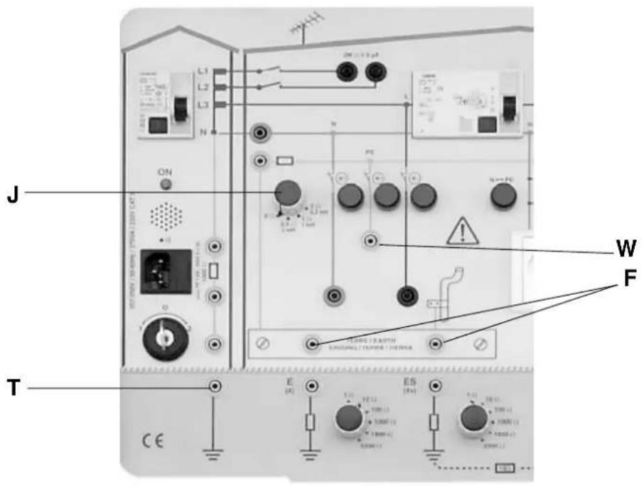
J ON W F T E E5 CE 100V 1.2 V 100V 1.2 V 100V 1.2 V 100V 1.2 V 100V 1.2 V 100V 1.2 V 100V 1.2 V 100V 1.2 V 100V 1.2 V 100V 1.2 V 100V 1.2 100V 1.2 100V 1.2 100V 1.2 100V 1.2 100V 1.2 100V 1.2 100V 1.2 100V 1.2 100V 1.2 100V 1.2 100V 1.2Figure 7
Continuity can be measured using the following instruments:
- C.A 6115N
- C.A 6511/13
- C.A 6521/23/25.
MEASUREMENT:
■ Connect the measurement instrument between points W (earth terminal) and F (earth bar of the building).
- if C.A 6115N: use the cable with 3 separate leads and connect the instrument to the measurement terminals with lead L1/L and the L2/N lead linked to the L3/PE lead.
- if C.A 6511/13 or C.A 6521/23/25/31/33: use the set of 2 red + black leads with banana plugs on the end.
■ Vary the resistance and the inductance of the PE earth conductor by adjusting switch J.
■ Activate measurement.
In the field, this is how electricians work when they want to make sure that the earth bar is connected to all the earths (earth terminals of the sockets, electric radiators, lights, etc.).
■ To make use of another variable resistance in the case's measurement circuit, connect up between points W and T, not forgetting to connect a terminal of the earth bar F to one of the earth rods E or ES.
text_image
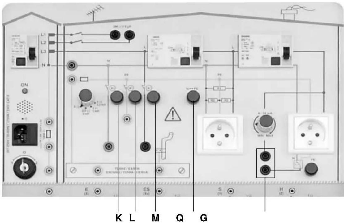
ON L1 L2 L3 N ON TURNE / EARN CIRCUING / TURNE / EARN E (E) K L M Q G S (Y) H (L)Figure 8
The following faults can be simulated:
■ Cut-off of the neutral with the non-locking button K
■ Cut-off of PE / earth with non-locking button L
■ Phase outage with non-locking button M.
■ Neutral earth (N - PE) inversion with non-locking button Q
■ Adjustable leakage current by connecting the two terminals G (see § 5)
10. TECHNICAL SPECIFICATIONS
10.1 Electrical
■ Characteristic values:
| Resistances for simulation C = 5 μF ±10%of insulation resistance on 2 MΩ // 5 μF circuit | R = 2 MΩ ±5%Maximum voltage: 1200 V DC |
| Resistances for simulationof insulation resistance on central socket | Between L and N: R = 0.99 MΩ ±5%Between L and PE: R = 26.8 MΩ ±5%Between N and PE: R = 26.8 MΩ ±5%Maximum voltage: 1200 V DC |
| Resistances for simulationof insulation resistance on right-hand socket | R = 6.3 kΩ ±5% + 47 kΩ ±10%Maximum voltage: 250 V AC |
| Impedance of PE conductor | R = 0 Ω +0.2 ΩR = 0,5 Ω ±0,3 Ω L = 2 mH ±10%R = 1 Ω ±0,3 Ω L = 1 mH ±10%R = 5 Ω ±10% L = 0,2 mH ±10%Imax : 1,6 A / 200 ms |
| Resistances for earth and resistivity measurement | R = 1 Ω, 10 Ω, 100 Ω, 1000 Ω, 1800 Ω, 2200 Ω, 4700 Ω (depending onearth) ±20% |
| Leakage current Approx. 4 to 34 mA with 230 V AC |
10.2 Dimensions and weight
■ Case: 490 x 395 x 195 mm ■ 10 kg
■ Packaging: 800 x 600 x 300 mm
10.3 Power supply
■207...250 V 50/60 Hz
■ Mains fuse: 1.6 A 250 V (or 380 V) type FF 5 x 20 HPC
■ 1 and 10 Ω resistances protected by a 16 A differential switch and the main fuse
■ Resistances of 100 to 4700 Ω protected by thermistor
■ Instantaneous power available: 400 VA
10.4 Environmental conditions
■ Temperature
- Operation: +5°C...+40°C
- Storage: -20°C...+70°C
- Indoor use
Watertightness (as per EN 60529, ed. 92):
- protection index IP 20B (open)
- protection index IP 40 (closed)
10.5 Compliance with standards
■ Electrical safety (according to low-voltage directive)
- Class-I instrument
- Installation category: II
- Pollution level: 2
- Rated voltage: relative to earth: 230 V
- Dielectric test voltage: 1350 Vrms 50 Hz
11. MAINTENANCE

For maintenance, use only specified spare parts. The manufacturer will not be held responsible for any accident occurring following a repair done other than by its After Sales Service or approved repairers.
11.1 Cleaning

The demo case must be disconnected from any source of electricity.
Use a soft cloth slightly moistened with soapy water.
Wipe with a wet cloth and dry quickly with a dry cloth or pulsated air. Do not use alcohol, solvents or hydrocarbons.
11.2 Calibration testing

It is essential that all measuring instruments are regularly calibrated.
For checking and calibration of your instrument, please contact our accredited laboratories (list on request) or the Chauvin Arnoux subsidiary or Agent in your country.
■ Maintenance
Repairs under or out of guarantee: please return the product to your distributor.
12. WARRANTY
Our guarantee is applicable for twelve months after the date on which the equipment is made available (extract from our General Conditions of Sale, available on request).
13. TO ORDER
C.A 6710 Electrical Installations demo case ....P01.1459.01 delivered with:
- 1 2P+E power cable, type schuko FRA/GER,
- 6 black safety leads 25 cm long with rewinders,
- 1 universal adapter for mains socket,
- 1 FRA → GER adapter for mains socket,
- 1 user's manual in 2 languages.
■ Spare parts:
6 Black safety leads 25 cm long with rewinders P01.2952.12
Universal adapter for mains socket....P01.1019.80
FRA® GER adapter for mains socket P01.1019.81

CHAUVIN
ARNOUX
12 - 2001