MiniFlex MA110 - Measuring equipment CHAUVIN ARNOUX - Free user manual and instructions
Find the device manual for free MiniFlex MA110 CHAUVIN ARNOUX in PDF.


| Product type | Flexible AC current sensor (type B per IEC 61010-2-032) |
| Models | MA110 (single-phase), MA130 (three-phase) |
| Coil length | MA110: 17 cm, 25 cm, 35 cm; MA130: 25 cm |
| Clamping diameter | 45 mm (17 cm), 70 mm (25 cm), 100 mm (35 cm) |
| Measurement ranges | 3 A, 30 A, 300 A, 3000 A (depending on model) |
| Output/input ratio | 1000 mV/A (range 3 A), 100 mV/A (30 A), 10 mV/A (300 A), 1 mV/A (3000 A) |
| Intrinsic accuracy | ≤1% + 40 mV (range 3 A); ≤1% + 4 mV (30 A); ≤1.5% + 0.4 mV (300 A I<10%); ≤1% + 0.4 mV (300 A I≥10%); ≤1.5% + 0.04 mV (3000 A I<10%); ≤1% + 0.04 mV (3000 A I≥10%) |
| Power supply | 2 alkaline 1.5 V batteries (AA/LR6) or 5 V micro-USB power adapter (optional) |
| Battery life | MA110: 300 h continuous / 1800 measurements of 10 min; MA130: 500 h continuous / 3000 measurements of 10 min |
| Dimensions of housing | 120 x 58 x 36 mm |
| Weight | MA110: approx. 300 g; MA130: approx. 500 g |
| Protection level | IP54 (housing), IP67 (flexible sensor) |
| Measurement category | 600 V CAT IV (housing) / 1000 V CAT III (sensor) |
| Frequency response | 10 Hz – 10 kHz (MA110); 10 Hz – 20 kHz (MA130); amplitude limitation beyond 300 A |
| Operating temperature | -10 °C to +55 °C |
| Relative humidity | 10% to 90% RH |
| Display / Indicators | Green On indicator, orange Auto Power Off, red OL (overload) |
| Maintenance and cleaning | Disconnect the device, clean with a soft cloth slightly soapy, rinse and dry; do not use alcohol or solvent. |
| Battery replacement | Unscrew the two screws of the housing, replace with AA/LR6 batteries respecting polarity, close |
| Warranty | 24 months, excluding improper use or unauthorized modification |
Frequently Asked Questions - MiniFlex MA110 CHAUVIN ARNOUX
User questions about MiniFlex MA110 CHAUVIN ARNOUX
0 question about this device. Answer the ones you know or ask your own.
Ask a new question about this device
Download the instructions for your Measuring equipment in PDF format for free! Find your manual MiniFlex MA110 - CHAUVIN ARNOUX and take your electronic device back in hand. On this page are published all the documents necessary for the use of your device. MiniFlex MA110 by CHAUVIN ARNOUX.
USER MANUAL MiniFlex MA110 CHAUVIN ARNOUX
MiniFlex® MA110 MiniFlex® MA130
natural_image
Two electrical test probes with labeled components, one connected to a black cable and the other holding a red loop (no visible text or symbols on devices)Flexible AC current sensors
Flexible AC- Stromwandler
5. GARANTIE ......20
6. POUR COMMANDER .....21
text_image
Diagram showing a hand holding a circular device with a red arc, before and after adjustment, indicating a change in the process.text_image
Diagram illustrating a medical procedure on a device, showing a cable being inserted into a device before and after change.text_image
P Auto Power Offline
| Frequency (Hz) | 3A | 30A | | -------------- | ------ | ------ | | 1 | 1.5% | 1.5% | | 10 | 0.5% | 0.5% | | 100 | 0.2% | 0.2% | | 1000 | 0.1% | 0.1% | | 10000 | 0.0% | 0.0% | | 100000 | -0.1% | -0.1% | | 1000000 | -2.5% | -4.5% | | 10000000 | -8.5% | -7.5% |natural_image
Pure technical line drawing of a mechanical component with no text or symbols
natural_image
Two technical line drawings: a rectangular plug and a cable with a bow (no text or symbols)Jeu de 5 attaches velcro
natural_image
Pure mechanical component diagram without any text, numbers, or symbolsThank you for purchasing an MiniFlex® MA110 or MA130 flexible current sensor.
For best results from your instrument:
■ read these operating instructions carefully,
■ comply with the precautions for use.

WARNING, risk of DANGER! The operator must refer to these instructions whenever this danger symbol appears.

WARNING, risk of electric shock. The voltage applied to parts marked with this symbol may be hazardous.

Equipment protected by double insulation. Earth.

Application or withdrawal authorized on conductors carrying dangerous voltages. Type B current sensor as per IEC 61010-2-032.

Battery. Direction of the current.


The product is declared recyclable following an analysis of the life cycle in accordance with standard ISO14040.

Chauvin Arnoux has adopted an Eco-Design approach in order to design this appliance. Analysis of the complete lifecycle has enabled us to control and optimize the effects of the product on the environment. In particular this appliance exceeds regulation requirements with respect to recycling and reuse.

The CE marking indicates conformity with European directives, in particular LVD and EMC.

The rubbish bin with a line through it indicates that, in the European Union, the product must undergo selective disposal in compliance with Directive WEEE 2002/96/EC.
Definition of measurement categories:
■ Measurement category IV corresponds to measurements taken at the source of low-voltage installations. Example: power feeders, counters and protection devices.
■ Measurement category III corresponds to measurements on building installations. Example: distribution panel, circuit-breakers, machines or fixed industrial devices
■ Measurement category II corresponds to measurements taken on circuits directly connected to low-voltage installations.
Example: power supply to electro-domestic devices and portable tools.
The MA110 is protected against voltages up to 600 V with respect to earth in measurement category IV, or 1000 V in category III. The MA130 is protected against voltages up to 600 V with respect to earth in measurement category III. The protection assured by the current sensor can be compromised if it is used in a way that is not recommended by the manufacturer.
■ Comply with the rated maximum voltage and current and the measurement category.
■ Never exceed the protection limits stated in the specifications.
■ Comply with the conditions of use, that is to say temperature, humidity, altitude, degree of pollution and location of use.
- Do not use the instrument if it is open, damaged, or incorrectly reassembled. Before each use, check the integrity of the insulation on the coil, the leads, and the electronic unit.
■ The application or withdrawal of the sensor on uninsulated conductors at dangerous voltages requires the use of suitable safety equipment.
If it is not possible to power down the installation, follow safe operating procedures and use suitable means of protection.
■ All troubleshooting and metrological checks must be done by competent, accredited personnel.
CONTENTS
1. PRESENTATION ......26
1.1. General .....26
1.2. Single-phase MiniFlex ^® .....26
1.3. Three-phase MiniFlex ^® .....27
2. CURRENT MEASUREMENT .....28
2.1. Measurement principle ......28
2.2. Use 28
2.3. Mains adapter (option) ......32
3. CHARACTERISTICS ......34
3.1. Reference conditions .....34
3.2. Electrical characteristics .....34
3.3. Variations in the range of use .....35
3.4. Typical frequency response curves ....36
3.5. Frequency limitation as a function of amplitude ....38
3.6. Power supply 38
3.7.Environmental conditions ....39
3.8. Construction specifications .....39
3.9. Conformity to international standards ....40
3.10. Electromagnetic compatibility (CEM) 40
4. MAINTENANCE ....41
4.1. Cleaning 41
4.2. Replacing the batteries .....41
5. WARRANTY 42
6. TO ORDER 43
6.1. Accessories and spares .....43
6.2. Specific models .....44
1. PRESENTATION
1.1. GENERAL
MiniFlex® sensors take the form of a flexible coil connected by a shielded lead to a housing containing the signal processing electronics, powered by batteries.
The flexibility of the sensors facilitates the clamping of the conductor to be measured, whatever its nature (cable, bar, strand, etc.) and its accessibility. The design of the coil opening and closing device, by snap locking, allows handling while wearing protective gloves.
The electronic unit can be connected to the mVac or Vac input of a measuring instrument having an input impedance of ≥ 1 M .
1.2. SINGLE-PHASE MINIFLEX®
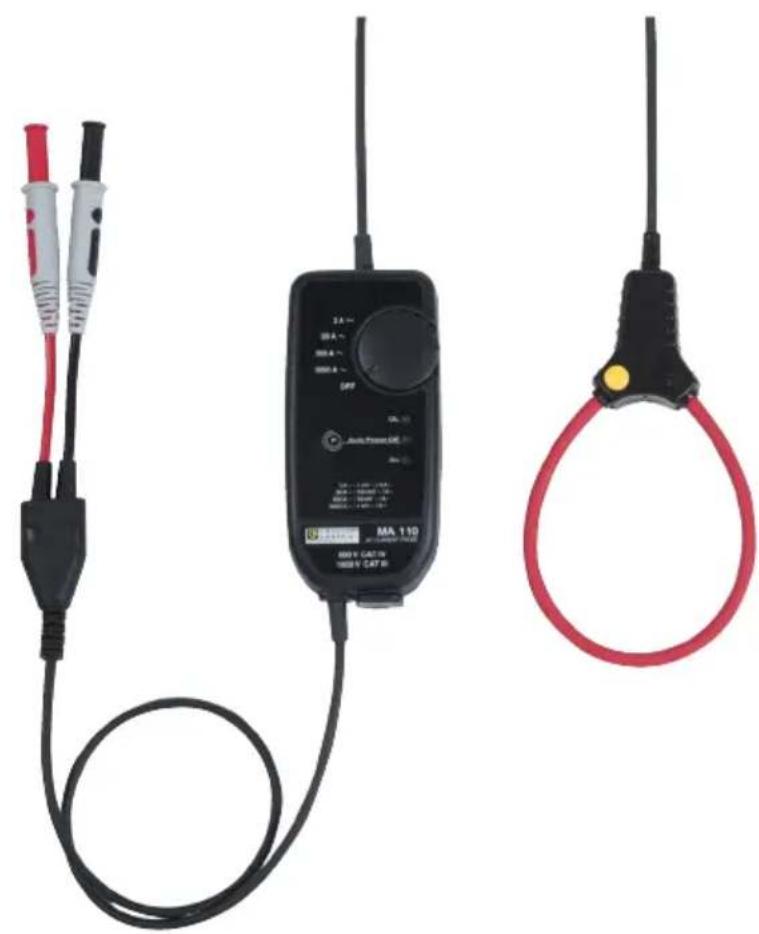
MiniFlex ^® series MA110 single-phase sensors constitute a line of three models, 17, 25, and 35 cm long, that convert alternating currents ranging from 3 to 3000 A into proportional AC voltages.
text_image
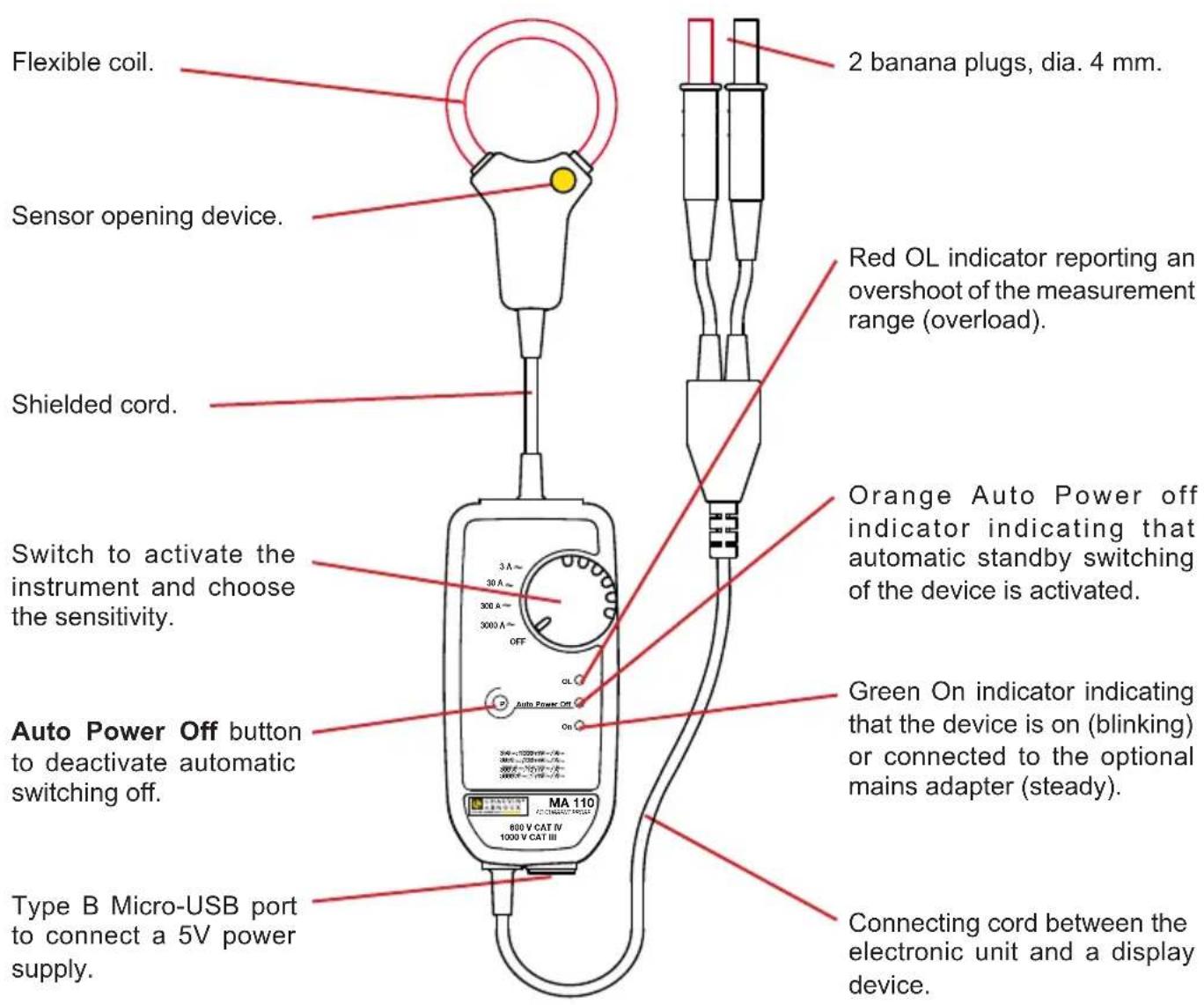
Flexible coil. Sensor opening device. Shielded cord. Switch to activate the instrument and choose the sensitivity. Auto Power Off button to deactivate automatic switching off. Type B Micro-USB port to connect a 5V power supply. 2 banana plugs, dia. 4 mm. Red OL indicator reporting an overshoot of the measurement range (overload). Orange Auto Power off indicator indicating that automatic standby switching of the device is activated. Green On indicator indicating that the device is on (blinking) or connected to the optional mains adapter (steady). Connecting cord between the electronic unit and a display device.1.3. THREE-PHASE MINIFLEX®
The MiniFlex ^® series MA130 sensor converts alternating currents ranging from 30 to 3000 A into proportional AC voltages. It comprises 3 sensors 25 cm long connected to the electronic unit. The output is via 3 BNC connectors on which it is possible to place the adapters provided in order to obtain outputs with 2 safety plugs.
The three outputs of the electronic unit can be connected to a standard wattmeter (as auxiliary inputs), to multimeters, to a recorder, etc.
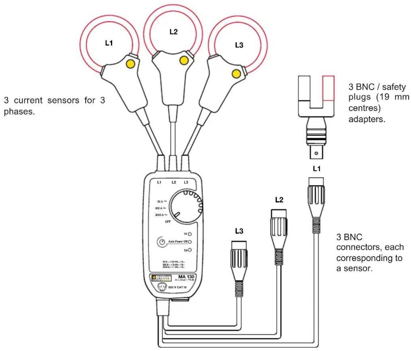
text_image
L1 L2 L3 3 current sensors for 3 phases. 3 BNC / safety plugs (19 mm centres) adapters. L1 L2 L3 3 BNC connectors, each corresponding to a sensor. MA 130 ACOS/NEUTRAL 800 V CAT III
The multimeter or instrument connected must have a maximum voltage and a measurement category at least equal to those of the MiniFlex® sensor, since otherwise the maximum voltage and category of the assembly will be those of the lowest-rated component.
2. CURRENT MEASUREMENT
2.1. MEASUREMENT PRINCIPLE
The sensors use the principle of the Rogowski coil.
The sensor used achieves:
■ very good linearity and no saturation effect (and so no overheating);
■ a wide measurement dynamic, up to several kA;
■ insensitivity to DC (measurement of the AC component of any AC + DC signal);
■ light weight (no magnetic circuit).
2.2. USE
2.2.1. CONNECTING THE MA110
Connect the output leads to a measuring instrument having an input impedance ≥ 1 M . Switch it on and set to AC voltage measurement.
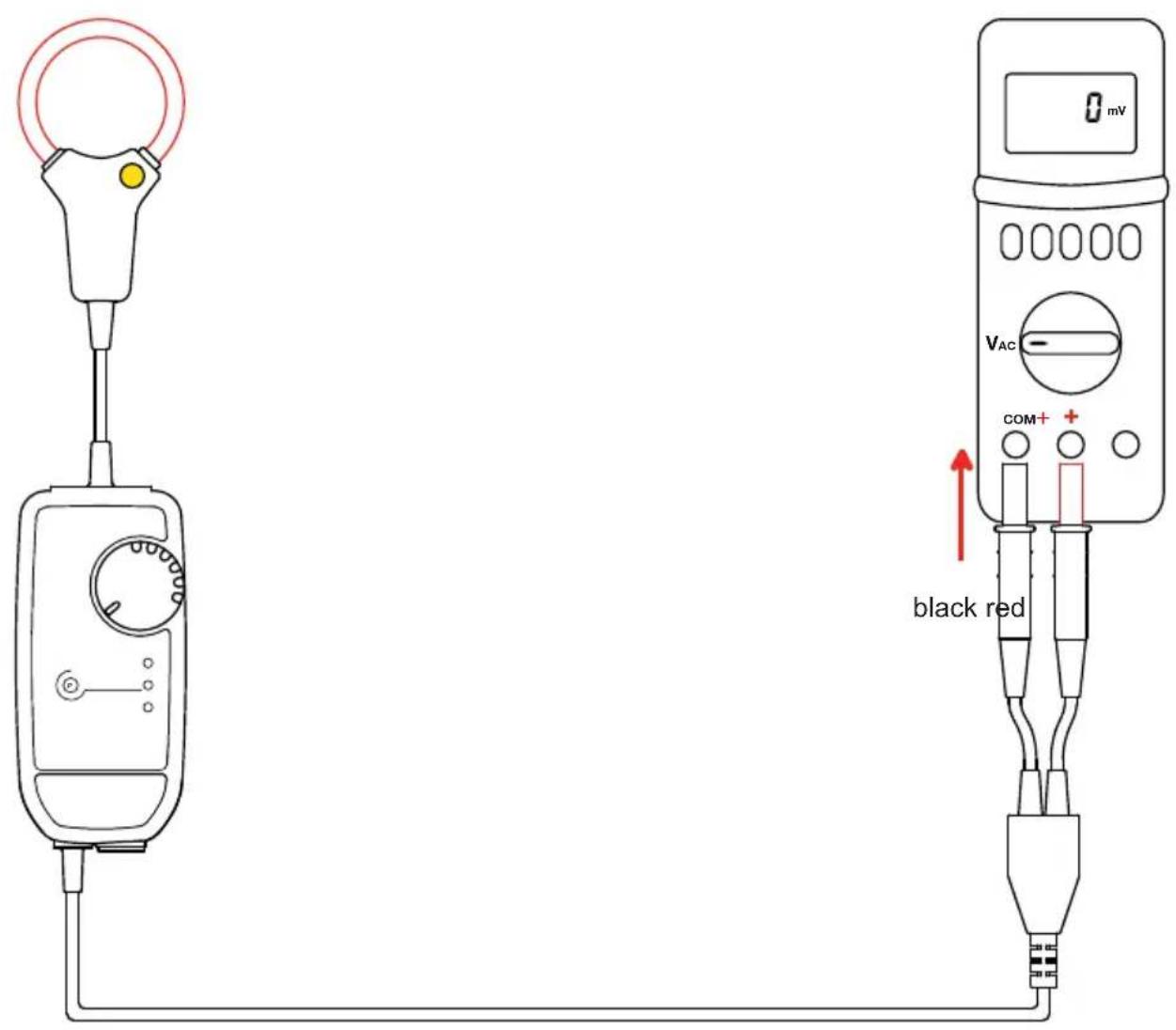
text_image
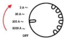
0 mV VAC COM+ black redPut the electronic unit into operation by turning the switch to some position. The green On indicator starts blinking.

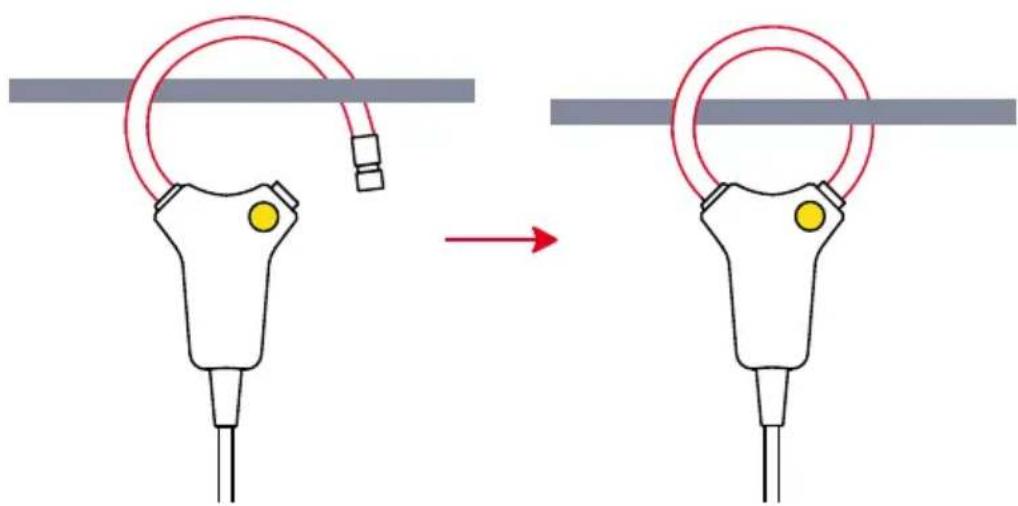
Press on the yellow opening device to open the flexible coil.
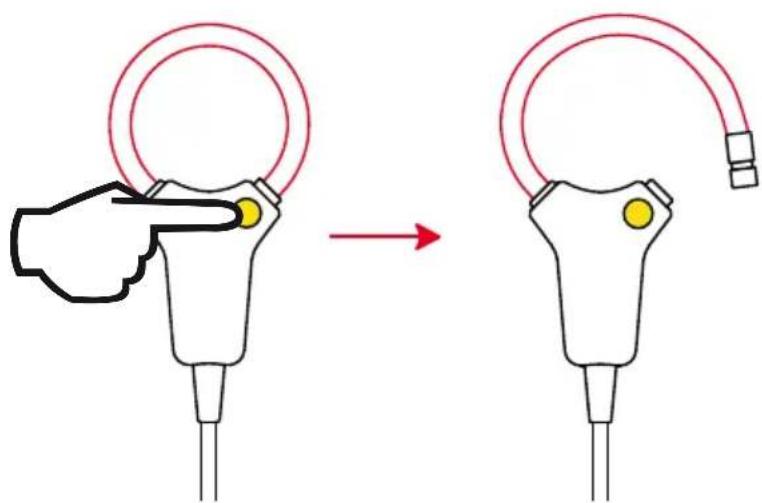
text_image
Diagram showing a hand holding a circular device with a red arc, before and after adjustment, indicating a change in the device's position.Open it and place it around the conductor carrying the current to be measured (only one conductor in the sensor). Close the coil. You must hear the "click".

In the case of an uninsulated conductor at a dangerous voltage, use individual protection equipment.
text_image
Diagram illustrating a medical procedure on a device, showing a cable being inserted into a device before and after treatment.To optimize measurement quality, centre the conductor in the coil.
Set the switch of the electronic unit to the range providing the best sensitivity and check that the red OL indicator is off (saturation of the electronics entailing a measurement error).
Read the measurement on the multimeter, applying the reading coefficient indicated on the label on the electronic unit corresponding to the setting of the switch.
3 A\~ range 1000 mV\~/A\~
30 A\~ range 100 mV\~/A\~
300 A\~ range 10 mV\~/A\~
3000 A\~ range 1 mV\~/A\~
Multiply the reading by the coefficient.
For example, a reading of 1 V on the measuring instrument corresponds to a current of 1 V10 mV/A = 100 A in the 300 A\~ range.
2.2.2. DISCONNECTING THE MA130
Withdraw the flexible coil from the conductor, set the switch to OFF, and disconnect the electronic unit from the multimeter.
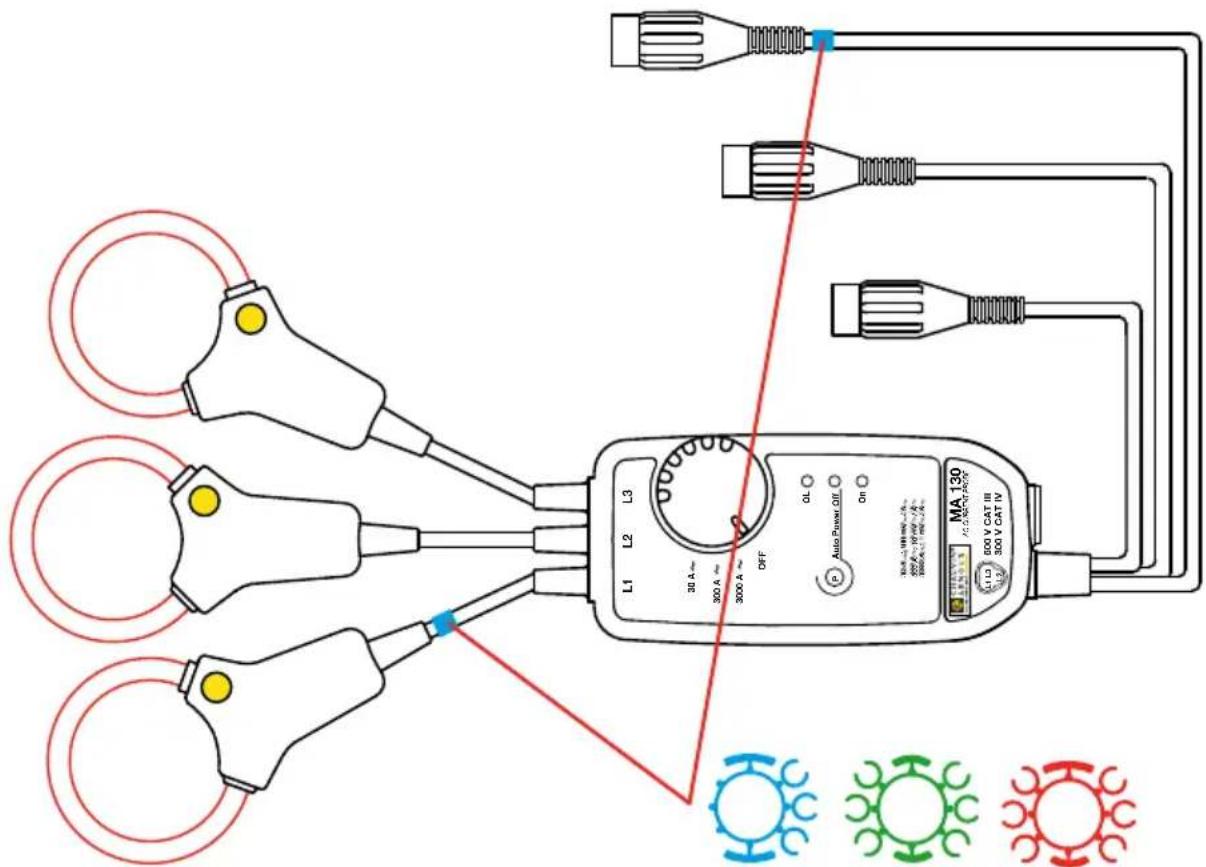
2.2.3. IDENTIFYING THE SENSORS OF THE MA130
To identify the sensors and the output leads, you can mark them with the coloured rings provided with the device.
Clip rings of the same colour on the sensor and on the corresponding output leads.
text_image
MA 130 L1 L2 L3 30 A~ 300 A~ 300 A~ OFF OL Auto Power Off On 30A~100V~40A~ 200A~50V~80A~ 300A~100V~120A~ L1 L2 L3 30 V CAT III 300 V CAT IV2.2.4. CONNECTING THE MA130
Proceed as for the MA110:
■ Connect the output leads to a measuring instrument.
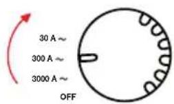
■ Put the electronic unit into operation by turning the switch to some position. The green On indicator starts blinking.

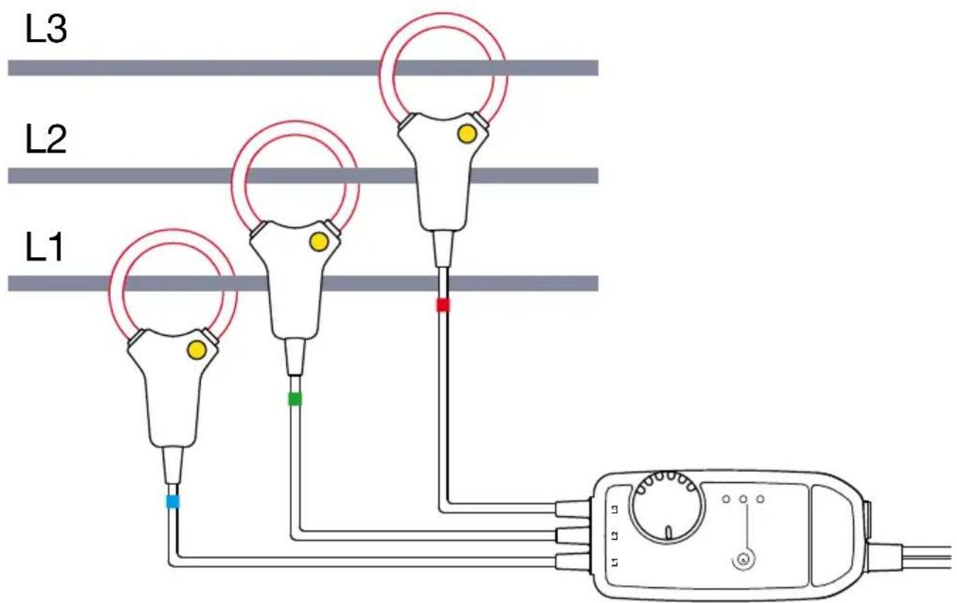
■ Open the 3 sensors and place them on the 3 phases.
text_image
L3 L2 L1 L1 L2 L3■ Set the switch on the electronic unit to the range providing the best sensitivity and check that the red OL indicator is off (saturation of the electronics entailing a measurement error).
- Read the measurement on the display device and apply the reading coefficient indicated on the label on the electronic unit corresponding to the setting of the switch.
30 A\~ range 100 mV\~/A\~
300 A\~ range 10 mV\~/A\~
3000 A\~ range 1 mV\~/A\~
2.2.5. DISCONNECTING THE MA130
Withdraw the 3 sensors from the 3 conductors, set the switch to OFF, and disconnect the electronic unit from the display device.
2.2.6. AUTOMATIC SLEEP MODE
When the device is started up, it operates for 10 minutes, then automatically switches itself to sleep mode in order to save the batteries.
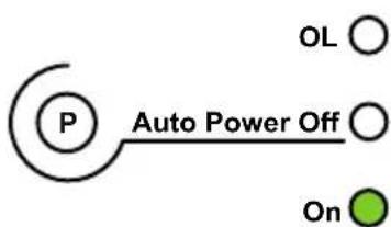
To report that the automatic power off function is active, the orange Auto Power Off indicator is lit.

text_image
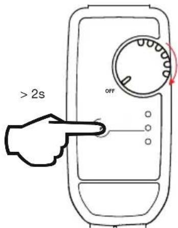
P Auto Power OffIt is possible to override automatic power off. This is done by switching the device on by turning the switch to one of the measurement positions and at the same time pressing the Auto Power Off button for more than 2 seconds. The orange Auto Power Off indicator remains off.
text_image
> 2s OFF2.3. MAINS ADAPTER (OPTION)
For long-duration measurements, it is possible to connect the electronic unit to line power.
Withdraw the protection from the type B micro-USB connector, then connect the lead. You can use any mains/micro-USB adapter that delivers 100 mA or more.

text_image
>90 VAC < 264 VAC 50 / 60 HzThe green On indicator remains on but its brightness varies to indicate that the batteries are OK.
flowchart
graph TD
    P((P)) --> AutoPowerOff["Auto Power Off"]
    AutoPowerOff --> OL((OL))
    AutoPowerOff --> On((On))
While the external power supply is present, automatic power off is disabled. But if the supply is cut off, the batteries take over and automatic power off acts at the end of 10 minutes.
If you make long-duration records, you must deactivate automatic power off (see § 2.2.6).
The insulation between the type B micro-USB connector and the measurement output is 1000 V CAT III or 600 V CAT IV. That makes it possible to connect the device without risk to wattmeters having uninsulated inputs. The type B micro-USB connector must not be in contact with conductors or uninsulated parts at dangerous voltages
3. CHARACTERISTICS
3.1. REFERENCE CONDITIONS
| Quantity of influence Reference values | |
| Temperature 23 ± 5 °C | |
| Relative humidity 20 to 75 % RH | |
| Frequency of the signal measured 30 to 440 Hz | |
| Type of signal sinusoidal | |
| Instrument turn-on time 1 minute | |
| External electric field null | |
| External DC magnetic field (earth's field) < 40 A/m | |
| External AC magnetic field null | |
| Position of the conductor in the coil centred | |
| Shape of the measurement coil circular, no applied stress | |
| Input impedance of the display device connected to the electronic unit | ≥ 1 MΩ |
3.2. ELECTRICAL CHARACTERISTICS
(3): Beyond 300 ARMS, see the curve at § 3.5.
| Model | Single-phase17, 25 and 35 cm | Three-phase25 cm | |
| Range 3 A | ▪ 30 A▪ 300 A▪ 3 000 A | ▪ 30 A▪ 300 A▪ 3 000 A | |
| Specified measurement range | 0,5 ... 3 A | ▪ 2 ... 30 A▪ 5 ... 300 A▪ 50 ... 3 000 A | ▪ 5 ... 30 A▪ 5 ... 300 A▪ 50 ... 3 000 A |
| Output/input ratio (mV~/A~) | 1000 | ▪ 100▪ 10▪ 1 | ▪ 100▪ 10▪ 1 |
| Maximum peak factor | 1.5 at IN (I nominal) | ||
| Intrinsic uncertainty(% of output signal) | ≤1%+40 mV | ▪ ≤1% + 4 mV▪ ≤1.5% + 0.4 mV (I<10% IN)≤1% + 0.4 mV (I≥10% IN)▪ ≤1.5%+ 0.04 mV (I<10% IN)≤1% + 0.04 mV (I≥10% IN) | ▪ ≤1% + 4 mV▪ ≤1.5% + 0.4 mV (I<10% IN)≤1% + 0.4 mV (I≥10% IN)▪ ≤1.5%+ 0.04 mV (I<10% IN)≤1% + 0.04 mV (I≥10% IN) |
| Max. offset voltage | 0 mVDC | ||
| Phase shift at 50 Hz | ≤1° (0.5° typical) | ||
| Max. output voltage | -4.5 Vpeak ≤ V ≤ + 4.5 Vpeak | ||
| Frequency response (3) | 10 Hz to10 kHz | 10 Hz to 20 kHz 10 Hz to | 20 kHz |

The peak value is limited only by the electronics of the measurement unit (red OL indicator on). The coil alone can briefly withstand higher peak factors with no risk of overheating or destruction.
3.3. VARIATIONS IN THE RANGE OF USE
| Quantity of influence Range of influence | influence | Error in % of reading | |
| Typical Maximum | |||
| Battery voltage 1.8 to 3.2V 0.02 | % 0.1 % | ||
| Temperature 10 to +55 °C 0.15 | % / 10 °C 0.50 % / 10 °C | ||
| Relative humidity 10 to 90%RH | 0.2 % 0.5 % | ||
| USB supply voltage 5 V 0.5 % 1 | 5 % | ||
| Position of the conductor in the undeformed sensor | Any position 1 % | 2.5 % | |
| Adjacent conductor carrying an AC voltage | Conductor touching sensor | 0.2 % | 1 %(2 % near snap lock) |
| Deformation of the sensor | Oblong shape | 0.2 % | 1 % |
| Common mode rejection | 600 V between the jacket and the secondary | 100 dB | 80 dB |
| Input impedance of the measuring instrument | 10 kΩ to 1 MΩ | 0.1 % | |
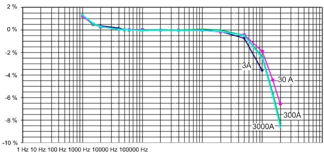
3.4. TYPICAL FREQUENCY RESPONSE CURVES
Single-phase, 3A, 30A, 300A, and 3000A ranges
line
| Frequency (Hz) | 3A | 30 A | | -------------- | ------ | ------ | | 10000 | 1.5% | 1.5% | | 10000 | 0.5% | 0.5% | | 10000 | 0.0% | 0.0% | | 10000 | -0.5% | -0.5% | | 10000 | -1.5% | -2.5% | | 10000 | -3.5% | -4.5% | | 10000 | -6.5% | -7.5% | | 10000 | -9.5% | -10.5% |Three-phase, 30A, 300A, and 3000A ranges
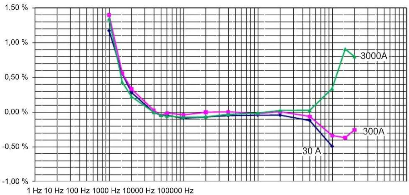
3.4.2. PHASE ERROR
Single-phase, 3A, 30A and 300A ranges
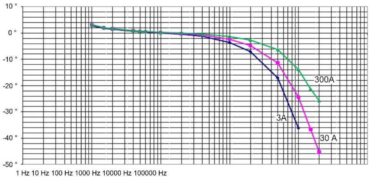
line
| Frequency (Hz) | 30 A | 3A | 300A | | -------------- | ------ | ------ | ------ | | 1 Hz | 0° | 0° | 0° | | 10 Hz | 0° | 0° | 0° | | 100 Hz | 0° | 0° | 0° | | 1000 Hz | 0° | 0° | 0° | | 10000 Hz | 0° | 0° | 0° | | 100000 Hz | 0° | 0° | 0° | | >100000 Hz | -45° | -35° | -25° |Three-phase, 30A, 300A and 3000A ranges
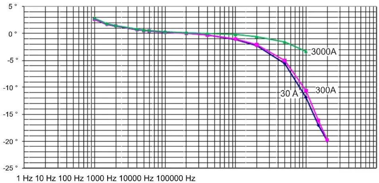
line
| Frequency (Hz) | 30A | 3000A | | -------------- | ----- | ----- | | 1 | 3.0 | 3.0 | | 10 | 2.5 | 2.5 | | 100 | 2.0 | 2.0 | | 1000 | 1.5 | 1.5 | | 10000 | 1.0 | 1.0 | | 100000 | 0.5 | 0.5 | | 1000000 | -5.0 | -5.0 | | 10000000 | -15.0 | -15.0 | | 100000000 | -25.0 | -25.0 |3.5. FREQUENCY LIMITATION AS A FUNCTION OF AMPLITUDE
In the 3A, 30A, 300A and 3000 A ranges:
In the 3A, 30A, and 300A ranges, with a frequency ≤ 20 kHz, there is no frequency derating.
3000A range
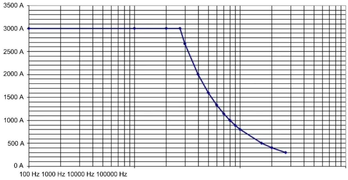
line
| Frequency (Hz) | Power (A) | | -------------- | --------- | | 100 | 3000 | | 1000 | 3000 | | 10000 | 3000 | | 100000 | 3000 | | 10000 | 2700 | | 100000 | 2000 | | 100000 | 1600 | | 100000 | 1300 | | 100000 | 1100 | | 100000 | 900 | | 100000 | 700 | | 100000 | 500 | | 100000 | 350 | | 10000 | 300 |3.6. POWER SUPPLY
3.6.1 BY BATTERIES
The device is powered by two 1.5 V alkaline batteries (type AA or LR6). The nominal operating voltage is lies between 1.8 and 3.2 V.
The mean battery life is:
■ MA110 single-phase
■ 300 h in continuous operation
■ 1,800 10-minute measurements
■ MA130 three-phase
■ 500 h in continuous operation
■ 3,000 10-minute measurements
When the device is not connected to line power and the green On indicator goes off, the batteries must be replaced (see § 4.2).
3.6.2. MAINS ADAPTER (OPTION)
The device can be powered by a standard mains adapter (5 VDC, 100 mA) with a type B micro-USB connector.
When the adapter is connected and the switch is set to OFF, the On indicator is lit steadily.
When the device is on, the brightness of the On indicator varies to indicate that the batteries are OK. If the indicator remains on steadily, the batteries must be replaced.
3.7. ENVIRONMENTAL CONDITIONS
The device must be used in the following conditions:
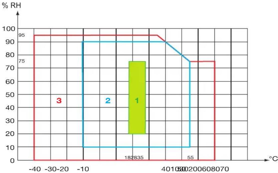
line
| Temperature (°C) | % RH | |---|---| | -40 | 95 | | -30-20 | 95 | | -10 | 95 | | 0 | 95 | | 182835 | 75 | | 4010 | 90 | | 55 | 80 | | 8060 | 75 | | 8070 | 75 |1: Range of reference
2: Operating range
3: Storage range (without battery)
For an extended period of non-use or storage, withdraw the batteries from the electronic unit. The sensor by itself can withstand a maximum temperature of 90^ C for 10 minutes.
Degree of pollution: 2.
Altitude: < 2000 m.
3.8. CONSTRUCTION SPECIFICATIONS
Coil
| Length (mm) 170 250 350 | |||
| Clamping diameter (mm) 45 70 100 |
Shielded lead 4 mm in diameter between the sensor and the electronic unit:
MA110: 2 metres long
MA130: 3 metres long
Electronic unit:
Overall dimensions: 120 x 58 x 36 mm
MA110: Output by a cable 50 cm long and 2 plugs 4 mm in diameter.
MA130: Output by a cable 50 cm long and 3 BNC connectors.
Mass of the device:
■ MA110: approximately 300 g.
■ MA130: approximately 500 g.
Protection index:
IP 54 for the electronic unit and IP 67 for the flexible sensor per IEC 60529.
The flexible coil stands up well to oils and aliphatic hydrocarbons.
3.9. CONFORMITY TO INTERNATIONAL STANDARDS
Electrical safety per IEC 61010-2-032 for type B sensors.
| Single-phase electronic unit and connecting cable to the measuring instrument | Three-phase electronic unit and connecting cable to the measuring instrument | Sensor and connecting cable to the electronic unit |
| Double insulation Double | insulation Double insulation | |
| Measurement category: IV Me | measurement category: III Measurement category: IV | |
| Rated voltage: 600V (1) | Rated voltage: 600 V Rated | voltage: 600V (1) |
(1): or 1000 V in category III.
The 250 V mains adapter (option).
3.10. ELECTROMAGNETIC COMPATIBILITY (CEM)
Emissions and immunity in an industrial environment per IEC 61326-1.

Except for the batteries, the instrument contains no parts that can be replaced by personnel who have not been specially trained and accredited. Any unauthorized repair or replacement of a part by an “equivalent” may gravely impair safety.
4.1. CLEANING
Disconnect the unit completely and turn the rotary switch to OFF.
Use a soft cloth, dampened with soapy water. Rinse with a damp cloth and dry rapidly with a dry cloth or forced air. Do not use alcohol, solvents, or hydrocarbons.
See to it that no foreign body interferes with the operation of the snap lock device of the sensor.
4.2. REPLACING THE BATTERIES
The batteries must be replaced when the On indicator remains off upon switching on.
■ Disconnect the unit completely and turn the rotary switch to OFF.
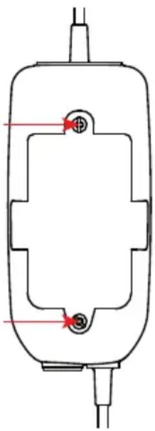
■ Use a screwdriver to unscrew the two screws closing the electronic unit.
■ Replace the spent batteries with new batteries (1.5V AA or LR6 alkaline batteries).
■ Place the batteries in their compartment, taking care with the polarities.
■ Close the electronic unit and make sure that it is completely and correctly closed.
■ Screw the two screws back in.
natural_image
Pure technical diagram of a mechanical component with no text, numbers, or symbols
Spent primary and storage batteries must not be treated as ordinary household waste. Take them to the appropriate collection point for recycling.
5. WARRANTY
Except as otherwise stated, our warranty is valid for 24 months starting from the date on which the equipment was sold. Extract from our General Conditions of Sale provided on request.
■ The warranty does not apply in the following cases:
■ Inappropriate use of the equipment or use with incompatible equipment;
■ Modifications made to the equipment without the explicit permission of the manufacturer's technical staff;
■ Work done on the device by a person not approved by the manufacturer;
Adaptation to a particular application not anticipated in the definition of the equipment or not indicated in the user's manual;
■ Damage caused by shocks, falls, or floods.
MiniFlex® series MA110 single-phase sensor - 170, 250 or 350 mm
Supplied in a cardboard box with:
■ two 1.5 V batteries (AA or LR6),
■ one multilingual safety data sheet,
■ a user manual in 5 languages,
■ a verification certificate.
MiniFlex ^® series MA130 three-phase sensor - 250 mm
Supplied in a cardboard box with:
■ two 1.5 V batteries (AA or LR6),
■ one set of 12 inserts and rings to identify the current sensors and the leads,
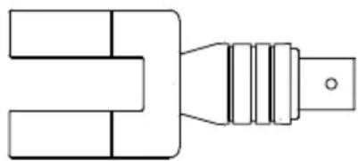
■ 3 female BNC / 2 male plug adapters ∅ 4mm (one red and one black), 19 mm centres,
■ one multilingual safety data sheet,
■ a user manual in 5 languages,
■ a verification certificate.
6.1. ACCESSORIES AND SPARES
Type B 5V 1A mains-micro USB adapter

natural_image
Two types of electronic components: a rectangular plug and a coiled cable with connectors (no text or symbols)Set of 5 Velcro fasteners
Set of inserts and rings to identify phases and current sensors
Set of 2 adapters, female BNC to 2 male plugs 4mm in diameter (one red and one black) with 19mm spacing
natural_image
Pure mechanical component diagram without any text, numbers, or symbolsFor the accessories and spares, consult our web site:
www.chauvin-arnoux.com
6.2. SPECIFIC MODELS
MiniFlex ^® series MA110 single-phase sensor
■ The sensors are available in specific lengths, from 20 to 100 cm in 5-cm increments.
The connecting cable between the sensor and the electronic unit is available in specific lengths, from 50 to 1000 cm in 10-cm increments.
MiniFlex® series MA110 three-phase sensor
■ The sensors are available in specific lengths, from 20 to 100 cm in 5-cm increments.
■ The connecting cable between the sensor and the electronic unit is available in specific lengths, from 50 to 1000 cm in 10-cm increments.
■ The output can take the form of:
■ 3 leads (from 50 cm to 300 cm long, in 10-cm increments) with two stripped and tinned conductors (instrument 600 V cat. III provided that a 600V cat. III connector is added on the conductors)
■ 3 coaxial cables 50 cm long terminated by an insulated male BNC connector (instrument 600 V cat. III)
■ 3 leads 50 cm long terminated by 2 insulated 4mm banana plugs, one red and one black (instrument 600 V cat. IV)
The characteristics of the sensors will be identical to those of the MA110 and MA130, but the pass band will be specified only up to 5 kHz.
The length of the cables may introduce further influences.

In all cases, for specific models, get in touch with our sales staff.
text_image
Diagram showing a hand holding a circular device with a red arc, before and after adjustment, indicating a change in the device's position.text_image
Diagram illustrating a medical procedure on a device, showing a cable being inserted into a device before and after change.text_image
P Auto Power Offline
| Frequency (Hz) | 3A | 30 A | | -------------- | ------ | ------ | | 10000 | 1.5% | 1.5% | | 10000 | 0.5% | 0.5% | | 10000 | 0.0% | 0.0% | | 10000 | -0.5% | -0.5% | | 10000 | -1.0% | -1.0% | | 10000 | -2.0% | -2.0% | | 10000 | -3.5% | -4.5% | | 10000 | -6.5% | -7.5% | | 10000 | -9.5% | -9.5% |line
| Frequency (Hz) | 30 A | 300A | 3000A | | -------------- | -------- | -------- | -------- | | 1 Hz | 1.20% | 1.40% | 1.45% | | 10 Hz | 1.15% | 1.35% | 1.38% | | 100 Hz | 1.10% | 1.25% | 1.28% | | 1000 Hz | 1.05% | 1.15% | 1.18% | | 10000 Hz | 0.95% | 1.05% | 1.08% | | 100000 Hz | 0.85% | 0.95% | 0.98% | | 1000000 Hz | 0.75% | 0.85% | 0.88% | | 10000000 Hz | -0.65% | -0.45% | -0.35% | | 100000000 Hz | -0.55% | -0.35% | -0.25% | | 1000000000 Hz | -0.45% | -0.25% | -0.15% | | 10000000000 Hz | -0.35% | -0.15% | -0.05% | | 100000000000 Hz| -0.25% | -0.05% | 0.15% | | 1000000000000 Hz| -0.15% | 0.15% | 0.25% | | 10000000000000 Hz| -0.15% | 0.25% | 0.35% | | 100000000000000 Hz| -0.25% | 0.35% | 0.45% | | 1000000000000000 Hz| -0.35% | 0.45% | 0.55% | | 1000000000000000 Hz| -0.45% | 0.55% | 0.65% | | 1000000000000000 Hz| -0.55% | 0.65% | 0.75% | | 100000000000000 Hz| -- | - | - |3.4.2. PHASENFEHLER
natural_image
Pure technical line drawing of a mechanical component with no text or symbols
natural_image
Two types of electronic components: a plug and a cord with connectors (no text or symbols)natural_image
Pure mechanical component diagram without any text, numbers, or symbolstext_image
Diagram showing a hand holding a circular device before and after adjustment, with a red arrow indicating the process.text_image
Diagram illustrating a medical procedure on a device, showing a cable being inserted into a device before and after change.text_image
P Auto Power Offline
| Frequency (Hz) | 3A | 30 A | 3000A | | -------------- | ------ | ------ | ------ | | 1 Hz | 1.5% | 1.5% | 1.5% | | 10 Hz | 1.2% | 1.2% | 1.2% | | 100 Hz | 0.5% | 0.5% | 0.5% | | 1000 Hz | 0.2% | 0.2% | 0.2% | | 10000 Hz | 0.1% | 0.1% | 0.1% | | 100000 Hz | 0.0% | 0.0% | 0.0% | | >100000 Hz | -2.5% | -4.5% | -8.5% |Trifase calibro 30 A, 300A e 3000A
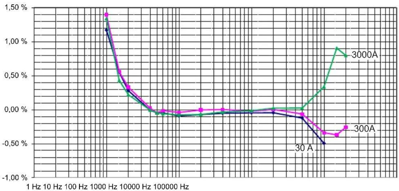
line
| Frequency (Hz) | 30 A | 300A | 3000A | | -------------- | -------- | -------- | -------- | | 1 Hz | 1.20% | 1.40% | 1.45% | | 10 Hz | 1.15% | 1.35% | 1.38% | | 100 Hz | 1.10% | 1.25% | 1.28% | | 1000 Hz | 1.05% | 1.15% | 1.18% | | 10000 Hz | 0.95% | 1.05% | 1.08% | | 100000 Hz | 0.85% | 0.95% | 0.98% | | 1000000 Hz | -0.55% | -0.45% | -0.48% |3.4.2. ERRORE DI FASE
Monofase calibro 3A, 30 A e 300A
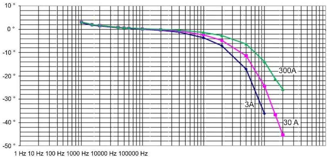
line
| Frequency (Hz) | 30 A | 3A | 300A | | -------------- | ------ | ------ | ------ | | 1 Hz | ~0° | ~0° | ~0° | | 10 Hz | ~0° | ~0° | ~0° | | 100 Hz | ~0° | ~0° | ~0° | | 1000 Hz | ~0° | ~0° | ~0° | | 10000 Hz | ~0° | ~0° | ~0° | | 100000 Hz | ~-5° | ~-5° | ~-5° | | >100000 Hz | -45° | -35° | -25° |Trifase calibro 30 A, 300A e 3000A
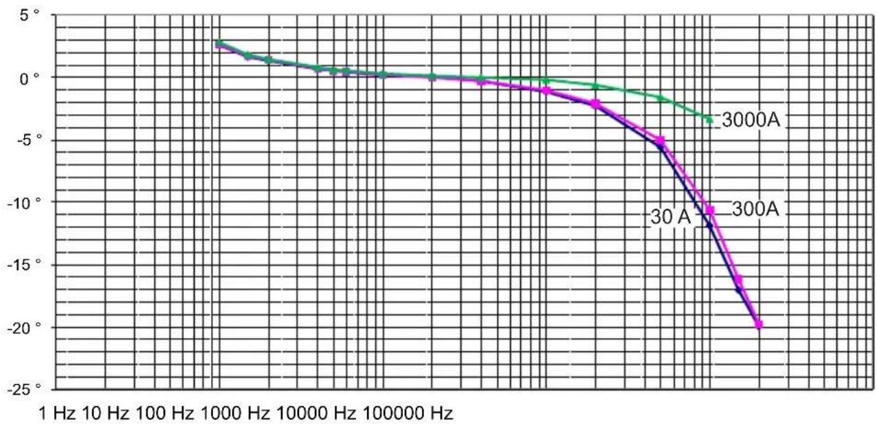
line
| Frequency (Hz) | 30A | 300A | 3000A | | -------------- | ------ | ------ | ------ | | 1 | ~3.5° | ~3.5° | ~3.5° | | 10 | ~3.0° | ~3.0° | ~3.0° | | 100 | ~2.5° | ~2.5° | ~2.5° | | 1000 | ~2.0° | ~2.0° | ~2.0° | | 10000 | ~1.5° | ~1.5° | ~1.5° | | 100000 | ~1.0° | ~1.0° | ~1.0° | | >1000 | ~-5° | ~-5° | ~-5° | | >100 | ~-10° | ~-10° | ~-10° | | >10 | ~-15° | ~-15° | ~-15° | | >1 | ~-20° | ~-20° | ~-20° |natural_image
Pure technical line drawing of a mechanical component with no text or symbols
natural_image
Two types of electronic components: a rectangular plug and a coiled cable with connectors (no text or symbols)natural_image
Pure mechanical component diagram without any text, numbers, or symbolstext_image
Diagram showing a hand holding a circular device before and after adjustment, with a red arrow indicating the process.text_image
Diagram illustrating a medical procedure on a device, showing a cable being inserted into a device before and after change.text_image
P Auto Power Offline
| Frequency (Hz) | 30 A | 300A | 3000A | | -------------- | -------- | -------- | -------- | | 1 Hz | 1.25% | 1.40% | 1.35% | | 10 Hz | 1.20% | 1.35% | 1.30% | | 100 Hz | 1.15% | 1.30% | 1.25% | | 1000 Hz | 1.10% | 1.25% | 1.20% | | 10000 Hz | 1.05% | 1.20% | 1.15% | | 100000 Hz | 1.00% | 1.15% | 1.10% | | 1000000 Hz | -0.50% | -0.45% | -0.40% | | 10000000 Hz | -0.65% | -0.45% | -0.35% | | 100000000 Hz | -0.75% | -0.35% | -0.25% | | 1000000000 Hz | -0.85% | -0.25% | -0.15% | | 10000000000 Hz | -0.95% | -0.15% | -0.05% | | 100000000000 Hz| -1.05% | -0.15% | 0.85% |natural_image
Pure technical diagram of a mechanical component with no text, numbers, or symbols
natural_image
Two types of electronic components: a plug and a cord with connectors (no text or symbols)natural_image
Pure mechanical component diagram without any text, numbers, or symbolsOur international contacts
www.chauvin-arnoux.com/contacts

CHAUVIN®
ARNOUX
CHAUVIN ARNOUX GROUP