
DNU-1541-7 - Sewing machine JUKI - Free user manual and instructions
Find the device manual for free DNU-1541-7 JUKI in PDF.

| Brand | Juki |
| Model | DNU-1541-7 |
| Category | Industrial sewing machine |
| Product type | Cylinder bed sewing machine for leather and heavy fabrics |
| Maximum sewing speed | 3000 stitches/min |
| Deliverable speed | 3000 stitches/min |
| Number of needles | 1 |
| Drive | Direct drive (beltless motor) |
| Lubrication type | Automatic lubrication (mentioned in manual) |
| Presser foot lift | Automatic and by knee lifter |
| Thread trimmer | Automatic |
| Control panel | CP-18 (digital) |
| Programmable functions | Back tack, reverse stitch, needle position, thread trimmer, various adjustments |
| Required air pressure | 0.4–0.5 MPa (4–5 kgf/cm²) |
| Power supply | Single-phase or three-phase depending on version (not specified, estimated: 200-240V, 50/60Hz) |
| Weight | Approximately 45 kg (estimate for similar industrial machine) |
| Dimensions (W×D×H) | Approximately 600×400×500 mm (estimate) |
| Maintenance | Regular cleaning, oiling, checking pneumatic connections |
| Safety | Emergency stop, protection against restart after power cut |
| Spare parts | Available from Juki or authorized dealers |
| Warranty | According to seller's conditions |
Frequently Asked Questions - DNU-1541-7 JUKI
User questions about DNU-1541-7 JUKI
0 question about this device. Answer the ones you know or ask your own.
Ask a new question about this device
Download the instructions for your Sewing machine in PDF format for free! Find your manual DNU-1541-7 - JUKI and take your electronic device back in hand. On this page are published all the documents necessary for the use of your device. DNU-1541-7 by JUKI.
USER MANUAL DNU-1541-7 JUKI
Sewing machines for leather and heavy-weight materials INSTRUCTION MANUAL (SUPPLEMENT) FOR SC-922
1) 機能設定モードへの入り方
natural_image
Technical line drawing of a mechanical component with no visible text or symbols
2. 位置検出器の取り付け

natural_image
Technical line drawing of a mechanical assembly with an arrow indicating direction (no text or symbols present)[例:LU-1500N-7 シリーズ]
DU-141H-7 / DSC / DSU

natural_image
Line drawing of a sewing machine with labeled component A (no text or symbols beyond label)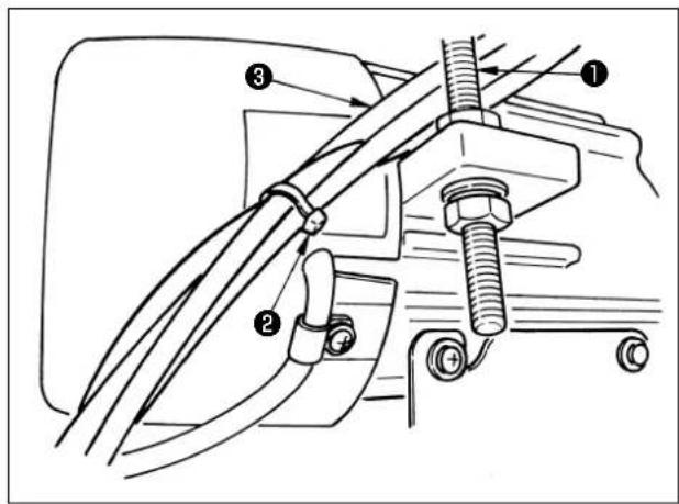
DSC

(1) 使い方
This Instruction Manual (supplement) gives additional explanation to the Instruction Manual for the respective models of sewing machines.
Applicable models
| Machine type Model | |
| Flat-bed type LU-22 | 00N-7 series, LU-1500N/1520NC-7 series,DNU-1541-7, DU-141H-7, LZH-1290-7 |
| Cylinder-bed type LS | S-1342-7, DSC series, DSU series |
| Post-bed type PLC | 1700 series |
CONTENTS
- SETTING OF THE MOUNTED MACHINE HEAD .... 1
- INSTALLING THE SYNCHRONIZER....2
- INSTALLING THE OPERATION BOX ....4
- INSTALLATION OF AK/AIR DEVICE....6
(1) INSTALLATION OF AK/AIR DEVICE....6
(2) AIR HOSE PIPING 6
(3) INSTALLATION OF THE KNEE SWITCH 8
(4) FUNCTION SETTING OF THE KNEE SWITCH 9
(5) HOW TO USE....10
(6) ADJUSTING THE LIFT OF THE PRESSER FOOT....10
- CONNECTING THE CORDS....11
- THREADING THE PANEL THREAD GUIDE....14
- ONE-TOUCH UTILITY MANUAL REVERSE FEED STITCHING 14
- FRONT TIE STITCHING....14
(1) HOW TO OPERATE 14
(2) POSITION OF THE SWITCH 14
-
RELAY CORD 15
-
LU-2220N-7 NEEDLE THREAD CLAMP FUNCTION....17
- LU-2200N-7 SERIES THICK THREAD CUTTING 18
- HOW TO COPE WITH THE NEEDLE BAR DOWN WHEN THE MACHINE MAKES A DOWN POSITION STOP....19
- TABLE OF SC-922 FUNCTION ITEMS IN ACCORDANCE WITH THE ADDITIONAL DEVICES ..... 20
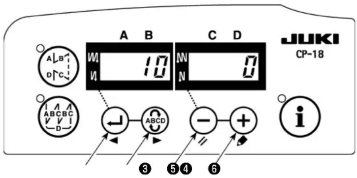
1. SETTING OF THE MOUNTED MACHINE HEAD
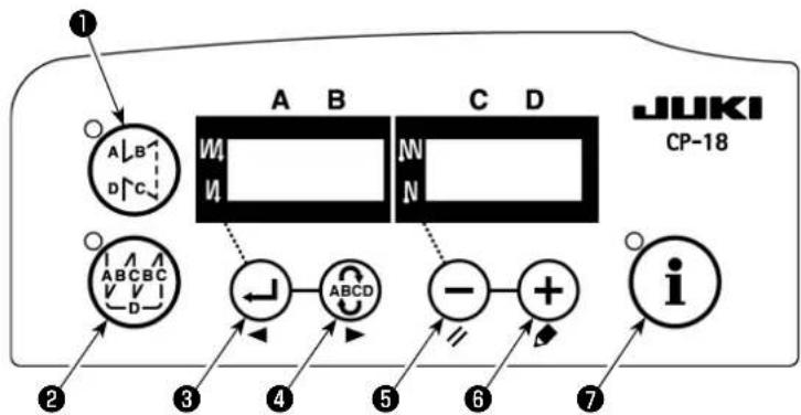
(Caution) For the function setting procedure of any operation panel other than CP-18, refer to the Instruction Manual for the operation panel to be used.
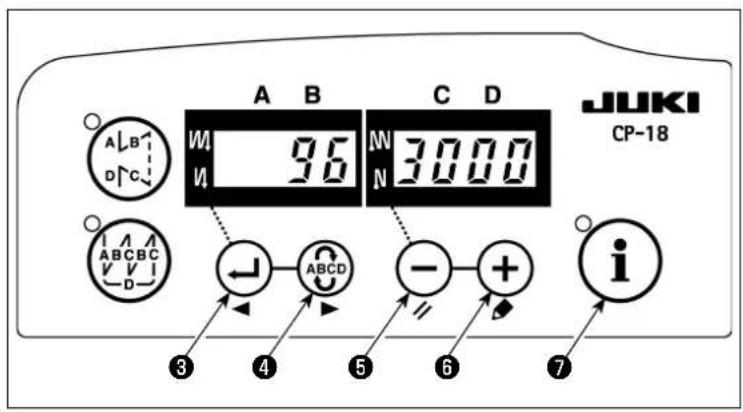
1) How to enter into the function setting mode
Turn ON the power with

⑦ held pressed. (The item which has been changed during the previous work is displayed.)
* If the screen display does not change, re-carry out operation described in step 1).
(Caution)
Be sure to re-turn ON the power switch when one or more seconds have passed after turning it OFF. If the power switch is re-turned ON immediately after turning it OFF, the sewing machine may fail to operate normally. In such a case, be sure to turn ON the power switch again properly.
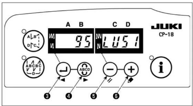
2) Press switch
③ or Switch
④ to call out function setting No.95 (mounted head).
3) Press ⏻ switch ⑤ or ⚠ switch
⑥ to select the mounted head. Refer to Table 1 (p.2) for the relationship between the head type and the panel display.
4) After selecting the head type, press
switch ③ or switch ④, and turn the power OFF.
(Caution)
If the power is turned OFF before car-rying out this procedure, the changed
content is not updated. When ⏻ switch
③ is pressed, the display on the panel changes to the previous setting No.
When ABCD switch ④ is pressed, the display on the panel changes to the subsequent setting No. After completion of the operation, the machine is returned to the normal sewing state by turning OFF the power and re-turning it ON.
List 1
| No. | Machine head Type | Contents of display | Number of revolutions at the time of delivery (sti/min) | Max. number of revolutions (sti/min) | |
| 1 | LU-2210N/2260N-7 (VR type) LU2v | LU3500 | 3500 | ||
| 2 | LU-2210N/2260N-7 (SW type) LU2r | LU3500 | 3500 | ||
| 3 | LU-2212N-7 (VR type) LU12 | LU13800 | 3500 | ||
| 4 | LU-2212N-7 (SW type) L12r | LU13500 | 3500 | ||
| 5 | LU-2216N/66N-7 (VR type) LU26 | LU3000 | 3000 | ||
| 6 | LU-2216N/66N-7 (SW type) L26r | LU28000 | 3000 | ||
| 7 | LU-2220N-7 (VR type) LU22 | LU3500 | 3500 | ||
| 8 | LU-2220N-7 (SW type) L22r | LU23500 | 3500 | ||
| 9 | LU-1510N-7 LU51 | LU53000 | 3000 | ||
| 10 | LU-1510NA-7 | LU5A | LU52000 | 2000 | |
| 11 | LU-1560N-7 LU56 | LU52500 | 2500 | ||
| 12 | PLC-1710/1760-7 | PL70 | PL7500 | 2500 | |
| 13 | PLC-1760L | PL7L | PL7800 | 1800 | |
| 14 | DNU-1541-7 | dnU5 | dn1000 | 3000 | |
| 15 | LS-1342-7 | LS13 | LS1500 | 2500 | |
| 16 | LU-1520NC-7 | LU5C | LU52000 | 2000 |
LU-2200N-7 (VR type)
natural_image
Technical line drawing of a mechanical component with no visible text or symbolsLU-2200N-7 (SW type)
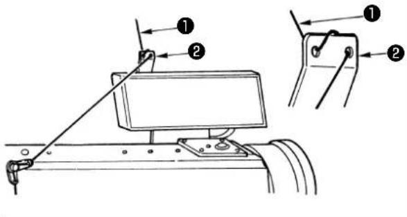
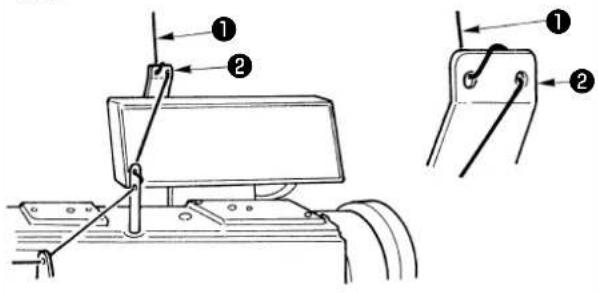
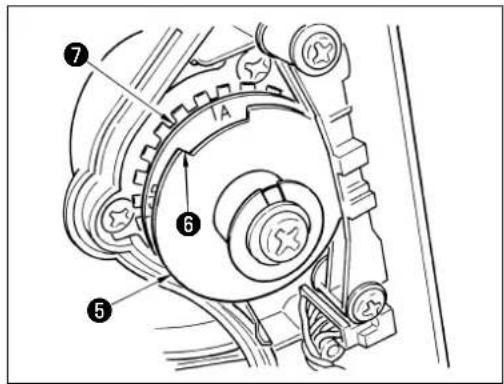
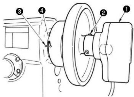
2. INSTALLING THE SYNCHRONIZER
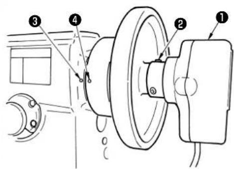
- Apply the adjustment below to the models which are not provided with built-in synchronizer.
- Be sure to confirm that the stop position is proper before performing the thread trimming operation.
Adjust the stop position in the state that the synchronizer is actually installed to the sewing machine. At this time, remove the connector for the sewing machine for safety's sake. When you remove a connector, please be sure to turn OFF the power.
When you adjust the UP position detecting plate ⑤, and when you turn the joint of synchronizer, please be sure to turn OFF the power. Set the needle UP/needle DOWN position setting with function No. 10 (specifying the needle bar position when the sewing machine stops).
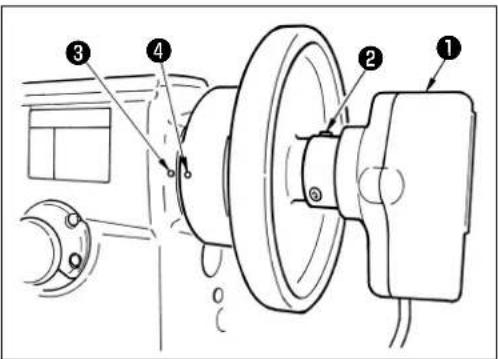
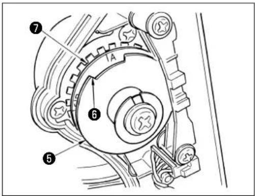
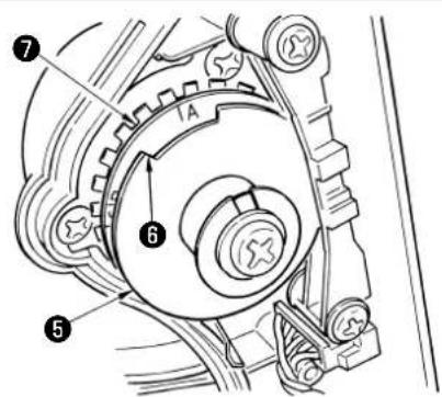
1) Temporarily fix synchronizer ① to the handwheel.
2) Remove the cover of synchronizer ①, and adjust edge section ⑥ of outside UP position detecting plate ⑤ to the position of scale of DOWN position detecting plate ⑦ in accordance with the respective models. For the position of scale of the respective models, refer to the list 2 (p.3).
3) Check first that the sewing-machine connectors have been removed. Then, place the sewing machine controller in the setting where the sewing machine stops with its needle down. Loosen setscrew ② of synchronizer ①. To adjust so that the sewing machine stops with its needle down, turn the joint to align engraved marker dot ④ on the handwheel which represents the lower position (i.e., the sewing machine stops with its needle down) with engraved marker dot ③ on the machine arm.
The location of the engraved marker dots on the handwheel which represents the stop position of the sewing machine differs with model. Refer to List 3 for the location of the marker dots of your sewing machine.
4) After adjusting DOWN stop, set the sewing machine controller to the needle UP position setting and confirm the UP stop position. When UP stop position is improper, perform fine adjustment with UP position detecting plate ⑤.
5) After adjusting the stop position, attach the cover of synchronizer ①. Return the sewing machine controller to the needle DOWN position setting.
List 2
| Model | Scale of DOWN position detecting plate 7 |
| LU-2200N series A | |
| DU-141H-7, DSC series, DSU series, LZH-1290-7 D |
List 3
| Model | Handwheel | ||
| Upper-position marker dot | Lower-position maker dot | Reverse-rotation needle-up position marker dot | |
| DU-141H-7, DSC series, DSU series Red White - | |||
| LZH-1290-7 Between red and red White - | |||
| LU-2200N series Between F and E K B | |||
■ How to set the needle bar position when the machine is stopped
Make the setting by function No.10 (needle bar position setting when the machine is stopped).
1) Refer to "1. Setting of the mounted head, 1) How to enter into the function setting mode" and enter into the function setting mode.
2) Press ← switch ③ or ABCD switch ④ to call out function setting No.10.
3) Press ⏻ switch ⑤ or ╗ switch ⑥ and select "0" or "1".
"0"...down position stop, "1"...up position stop
4) After the setting is made, press switch ③ or ABCD switch ④, and turn the power OFF.
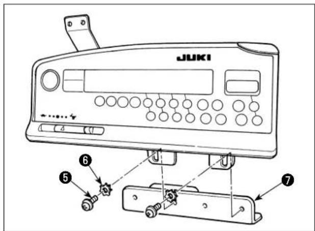
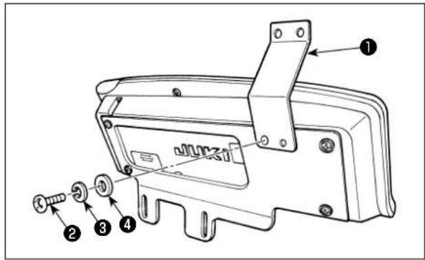
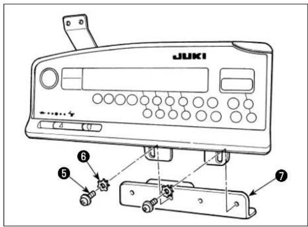
1) Install panel thread guide ① to the installing plate with screw ②, spring washer ③ and washer ④ supplied as accessories. However, panel thread guide ① is not installed to LU-1500N series, LS-1342-7, and DNU-1541-7.
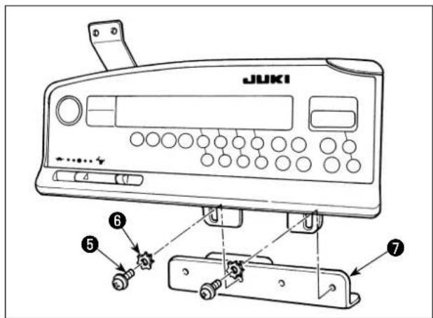
2) Install the operation box to the sewing machine using screws ⑤, washers ⑥ and toothed lock washers ⑦ supplied as accessories.
For the DU-141H-7 and DSU, however, screw ⑧ supplied with the sewing machine head should be used instead of screw ⑤ supplied with the operation box. In the case of installing the operation box to section
A, it should be installed only with screw ⑧ instead of washer ⑥ and toothed washer ⑦ supplied with the operation box.
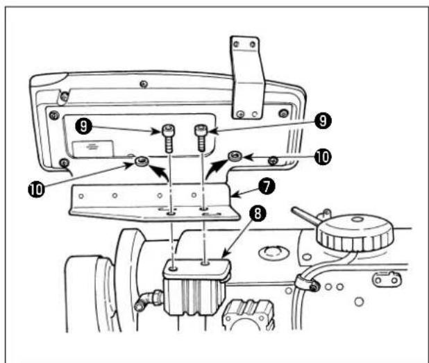
[ LU-2200 series ]
Please perform Procedures 1) to 4) except LU-22*6N series (long arm).
LU-22*6N series (long arm) should perform only Procedure 5).
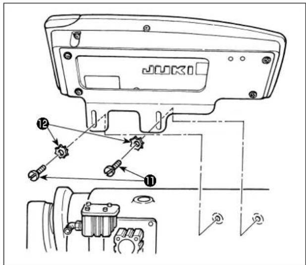
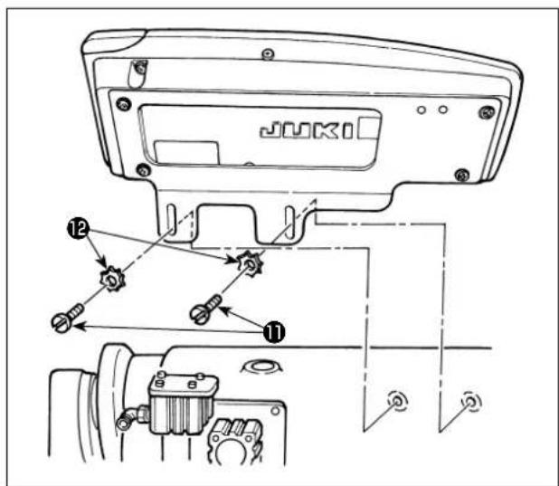
1) Install panel thread guide ① to the installing plate with screw ②, spring washer ③ and washer ④ supplied as accessories.

2) Install the operation box to panel installing auxiliary plate ⑦ with screws ⑤ and washers ⑥ supplied as accessories.

3) Remove setscrews ⑨ and flat washers ⑩ attached to reverse feed cylinder installing base ⑧. (2 pcs. each)
4) Install panel installing auxiliary plate ⑦ to reverse feed cylinder ⑧ with setscrews ⑨. At this time, flat washers ⑩ are not used.

5) Install the installing plate with setscrews ⑪ and washers ⑫.
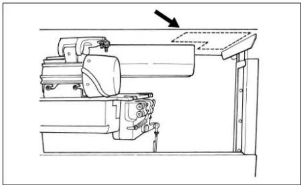
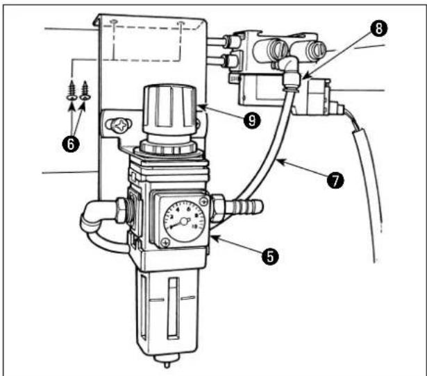
4. INSTALLATION OF AK/AIR DEVICE

WARNING :
Turn OFF the power before starting the work so as to prevent accidents caused by abrupt start of the sewing machine.
natural_image
Technical line drawing of a mechanical assembly with an arrow indicating direction (no text or symbols present)Install the regulator and the solenoid valve (asm.) of the AK/air device at the location indicated by a dotted line.
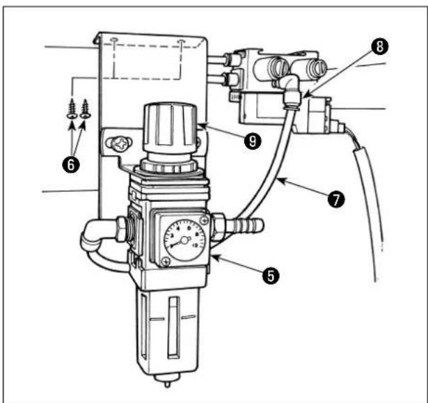
(1) Installation of AK/air device
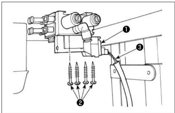
1) Install the solenoid valve (asm.) ① on the bottom surface of the table using the wooden screws ② supplied with the unit. At this time, be careful that the cord ③ of the solenoid valve (asm.) will not touch the legs.
(2) Air hose piping
(Caution) 1. Take care not to insert the air hoses to wrong quick coupling joints.
- Fully insert the air hoses into the quick coupling joints taking care not to allow air to leak.
- Carefully prevent the air hoses from bending.
[In case the air hose number is indicated on the solenoid valve (asm.)]
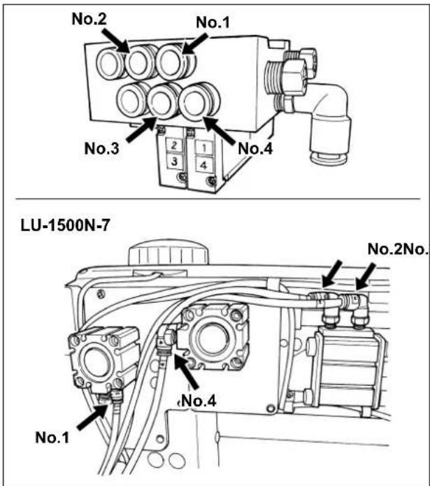
[Example: LU-1500N-7 series]
1) Connect the air hose of each number to the joint with the number indicated on the cylinder at the head. If the air hose is too long, cut it to an appropriate length.
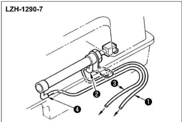
[In case the air hose number is not indicated on the solenoid valve (asm.) (LZH, DU-141H, DSC, DSU)]
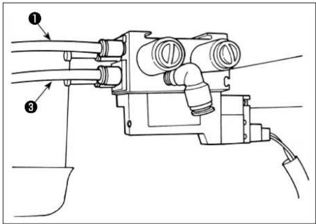
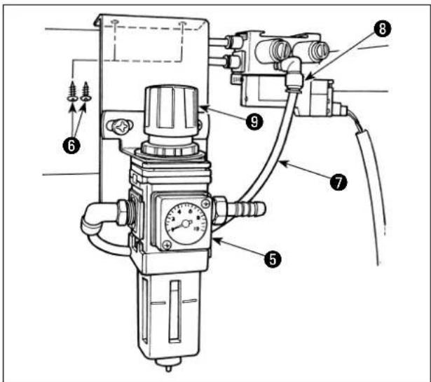
1) Connect air hose ① to joint ② and connect air hose ③ to joint ④. If the air hose is too long, cut it to an appropriate length.
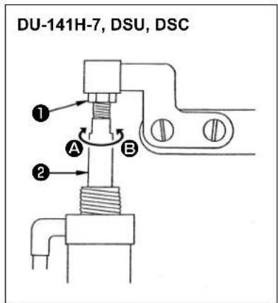
DU-141H-7 / DSC / DSU

2) Install regulator ⑤ on the bottom surface of the table using the wooden screws ⑥ supplied with the unit. Connect air hose ⑦ of the regulator to joint ⑧ of the solenoid valve (asm.).
3) When all the piping has been completed, adjust the air pressure to 0.4 to 0.5 MPa (4 to 5 kgf / cm^2 ) using knob ⑨ of the regulator.
(3) Installation of the knee switch
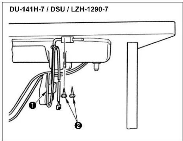
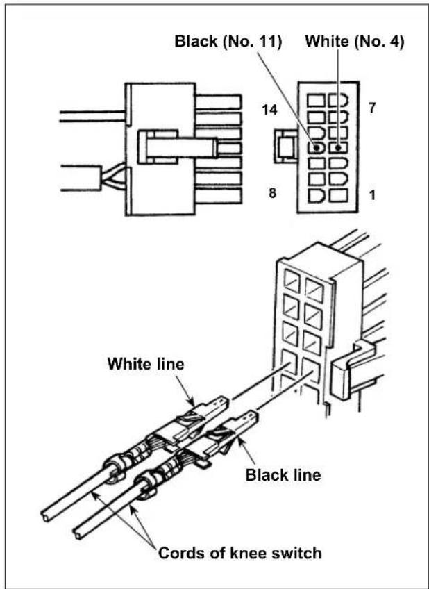
1) Install the knee switch (asm.) ① on the bottom surface of the table using the wooden screws ② supplied with the unit.
2) Connect the knee switch to No. 4 and No. 11 pins of the machine connector 14P which is connected to CN36 of the machine controller.
(4) Function setting of the knee switch
1) Refer to "1. Setting of the mounted head, 1) How to enter into the function setting mode" and enter into the function setting mode.
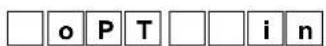
2) Press ← switch ③ or ← switch ④ to call out function setting No.12 (option input/output function selection).
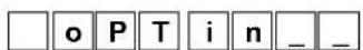
3) Press ⏻ switch ⑤ or ⏻ switch ⑥ and select the item for "in".
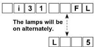
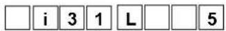
4) Press ABCD switch ④ and select display i31.
5) Press ⏻ switch ⑤ or ⏻ switch ⑥ to select the knee switch function. Refer to list 4 for the details of the functions.
6) Press ABCD switch ④ and fix the function.
7) Press ④ switch ④ and end the option input.
8) Select "End" item using ⏻ switch ⑤ or ⏻ switch ⑥.
9) Press ← switch ③ or ABCD switch mode.
List 4
| Function code | Abbreviation | Functional item Remarks | |
| 5 FL Presser lifter switch function | Presser output will be ON while | the switch is being pressed. | |
| 31 ALFL Presser lifter alternate | switch function Presser output will be ON | or OFF each time the switch is pressed. | |
| 24 vErT Alternate vertical movement amount conversion alternate switch function | Alternate vertical movement amount output will be ON or OFF each time the switch is pressed. | ||
| 25 vSW Alternate vertical movement amount conversion switch function | Alternate vertical movement amount output will be ON while the switch is being pressed. | ||
(5) How to use
1) When the pedal is in the neutral position, press the knee switch or lightly depress the back part of the pedal, and the presser foot can be raised as long as you keep either of them held depressed.
2) The presser foot automatically goes up after thread trimming, and the presser foot is lowered by depressing the front part of the pedal to allow the machine to start sewing. Presser foot can be lowered by depressing the knee switch once and returning it to the home position or depressing the back part of the pedal and returning it to the neutral position.
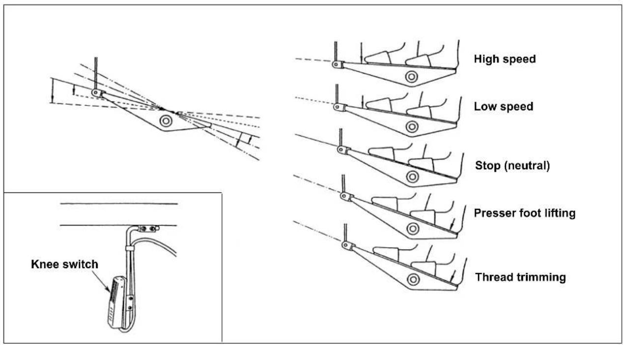
(6) Adjusting the lift of the presser foot
| Sewing machine Part to go up | Lifting amount (mm) | |
| DU-141H-7 Lift of the intermediate presser 15 | ||
| DSU series Lift of the intermediate presser 13 | ||
| DSC series Lift of the feeding frame 13 | ||
(For the LZH-1290-7, the lift of the presser is set to 15 mm.)
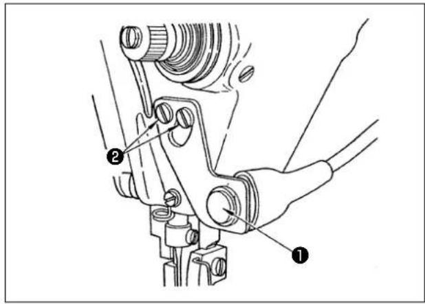
1) Loosen adjusting nut ① and turn cylinder rod ② to adjust so that the lift of the relevant presser foot is set to the aforementioned values when the cylinder is fully retracted. turn in direction A to decrease the lifting amount or in direction B to increase it.
2) After the completion of the adjustment, tighten adjusting nut ①.
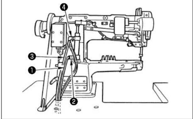
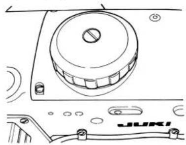
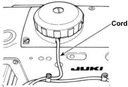
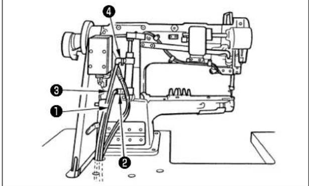
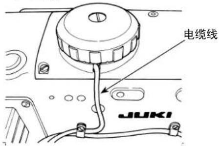
5. CONNECTING THE CORDS

WARNING :
Turn OFF the power before starting the work so as to prevent accidents caused by abrupt start of the sewing machine.
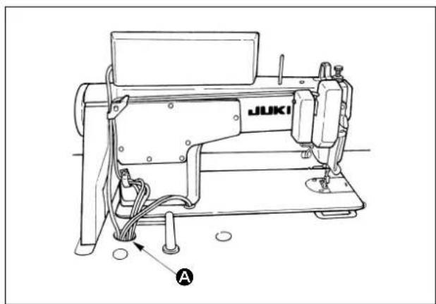
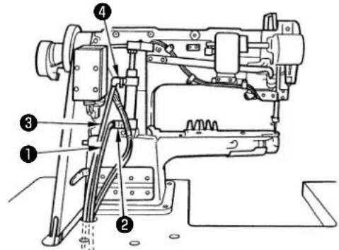
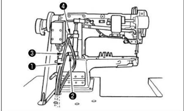
1) Pass the cords coming from the sewing machine through hole A in the table and route them down under the table.
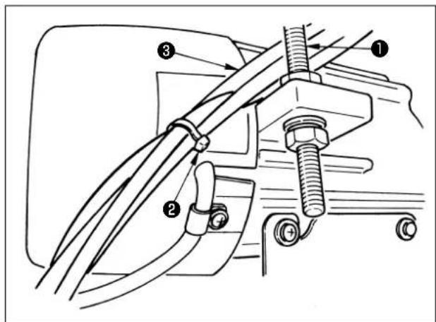
2) Pass the cords ③ coming from the sewing machine between belt tension adjusting bolt ① and the motor taking care not to allow the cords to come in contact with the belt.
3) Bundle cords coming from the sewing machine with clip band ②.
4) Connection of the cords
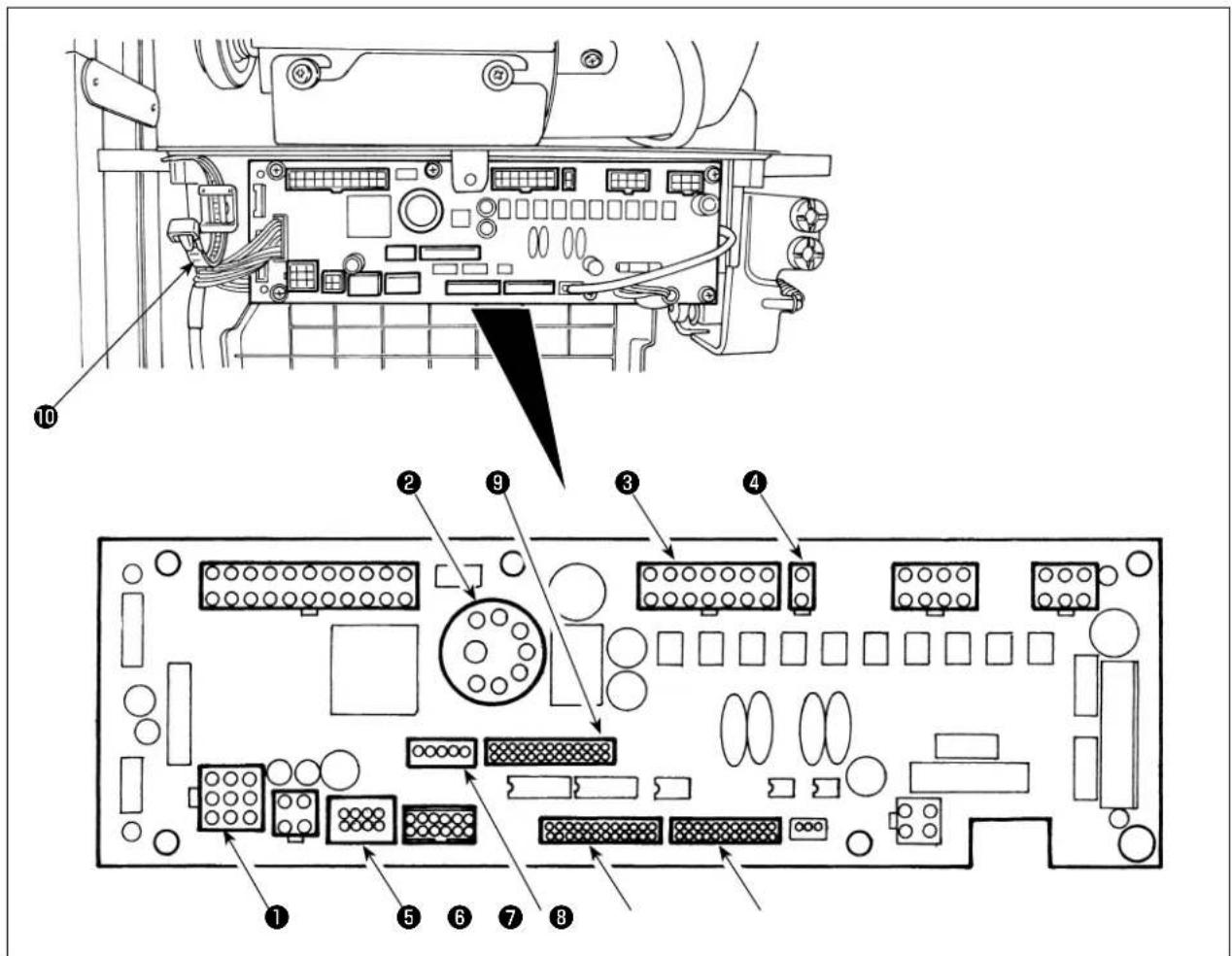
① CN30 Motor signal connector
② CN33 Externally installed needle bar synchronizer (+5V version): The needle bar position is detected.
⑧ CN36 Machine head solenoid: Provided with solenoids for thread trimming, reverse feed stitching, one-touch type reverse feed switch.
④ CN37 Presser foot lifting solenoid (Only for the automatic presser foot lifter type)
⑤ CN38 Operation panel: Various kinds of sewing can be programmed. (For details of the operation panel other than CP-18, refer to the Instruction Manual for the panel to be used.)
⑥ CN43 Built-in needle position synchronizer of the machine head (+12V version): The needle bar position is detected
⑦ CN44 Hand switch: Hand switch other than the touch-back switch.
⑧ CN58 Extended input connector (for the sensor input, etc.)
⑨ CN59 Extended output connector (for the solenoid valve output)
1) Connect the motor signal connector, needle bar synchronizer, operation panel and junction cord to the sewing machine controller.
After inserting the connector, put all cords together with cable clip band 10 located on the side of the box.
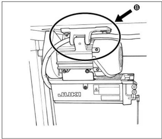
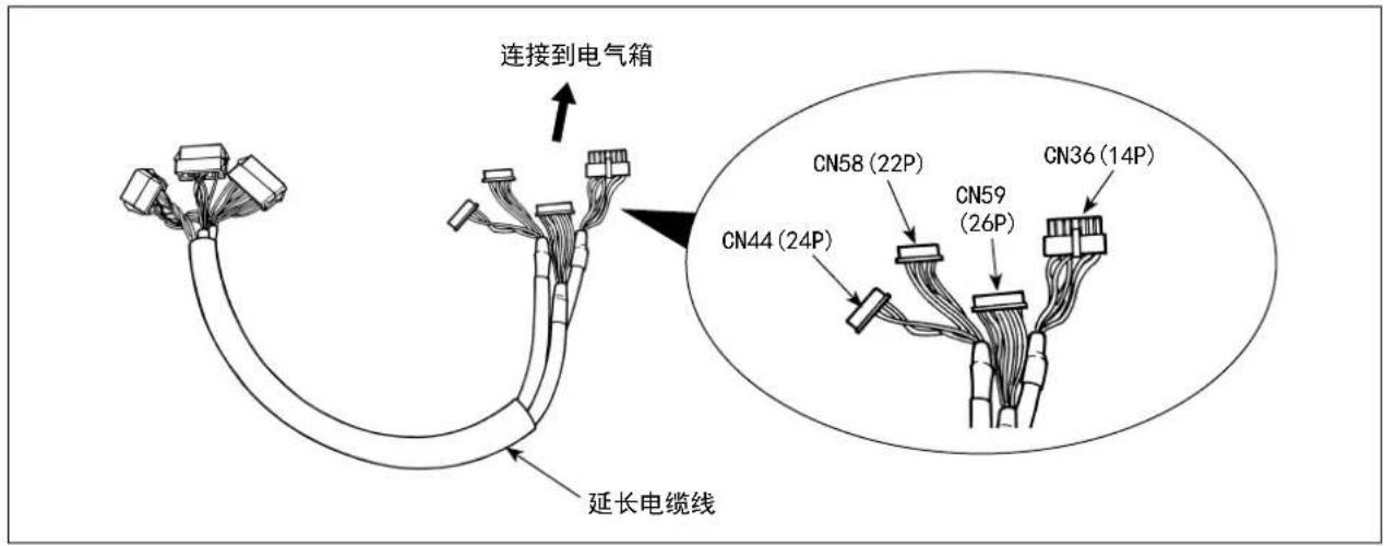
2) Make the relay cord run through as shown in Ⓔ.
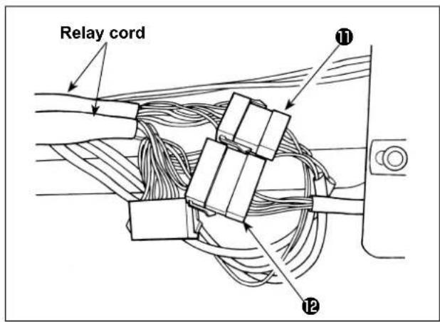
3) Connect connector ⑪ from the head and connector ⑫ from the solenoid valve (asm.) to the relay cord.
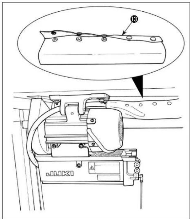
4) Bundle the air hose, the relay cord and others using a button tube ⑬.
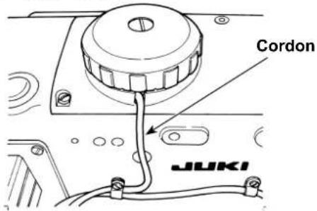
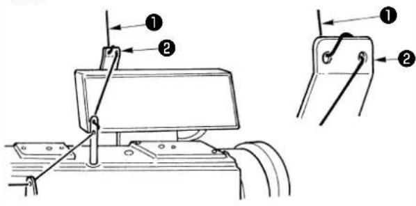
6. THREADING THE PANEL THREAD GUIDE
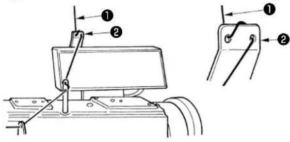
[DU-141H-7, DSU, DSC, LZH-1290-7]
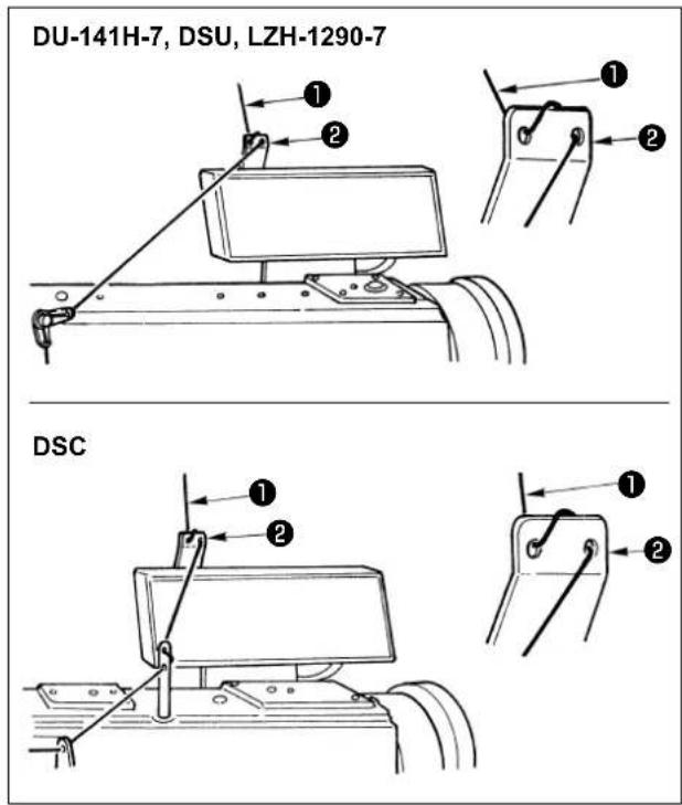
Pass needle thread ① coming from the thread stand through the hole in panel thread guide ②.
DU-141H-7, DSU, LZH-1290-7
DSC
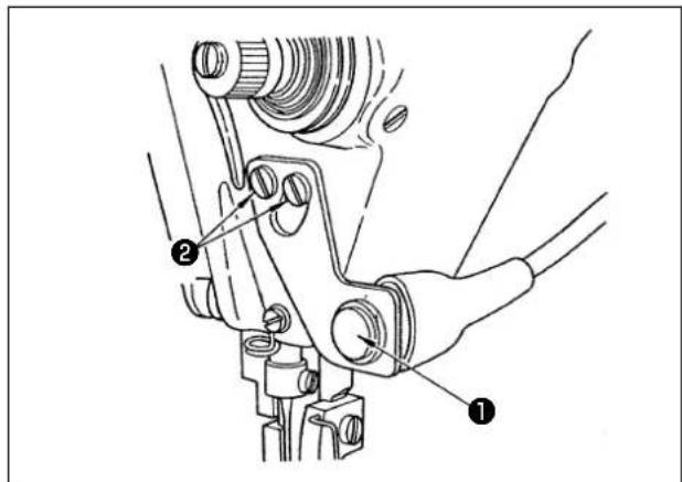
7. ONE-TOUCH UTILITY MANUAL REVERSE FEED STITCHING

(1) How to operate
1) The moment switch ① is pressed, the machine feeds the material in the reverse direction and performs reverse feed stitching.
2) The machine performs reverse feed stitching as long as the switch is held pressed.
3) The machine resumes normal feed stitching at the moment when the switch is released.
(Caution) Do not strongly press or strike the switch. The switch may be damaged.
(2) Position of the switch
1) Approximately position the switch so that you can operate it with ease.
2) Loosen screws ② and adjust the position of the switch by moving it up or down.
8. FRONT TIE STITCHING
flowchart
graph TD
    A["Normal feed"] --> B["Down Arrow"]
    B --> C["Arrow Right"]
    B --> D["Arrow Down"]
    B --> E["Arrow Left"]
    style B fill:#f9f,stroke:#333,stroke-width:2px
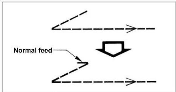
In the case where stitch skipping occurs at the start of sewing when performing single tie stitching ("V" tie stitching), perform 1 to 2 stitches of normal feed at the start of sewing.
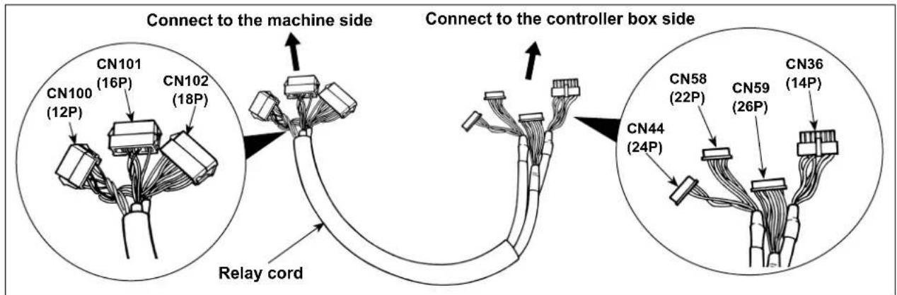
9. RELAY CORD
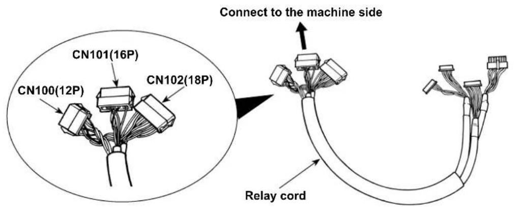
| CN100 (12P) Pin No. Function | ||
| For the head solenoid | 1 TRM Mg (-) | |
| 7 TRM Mg (+) | ||
| 2 TR Mg (-) | ||
| 8 TR Mg (+) | ||
| 12 FG | ||
| 9 GND | ||
| 10 BT SW | ||
| 3 +12V | ||
| 11 DL Volume | ||
| 4 DL Limit SW1 | ||
| 5 DL Limit SW2 | ||
| 6 GND | ||
| CN101 (16P) Pin No. Function | ||
| For the touch back switch asm. | 1 BT SW | |
| 2 DL SW | ||
| 3 ABT SW | ||
| 10 NU SW | ||
| 11 2P SW | ||
| 6 TC SW | ||
| 9 GND | ||
| 14 GND | ||
| 13 +24V | ||
| 4 DLSW LED | ||
| 12 2PSW LED | ||
| 5, 7, 8, 15, 16 - | ||
| CN102 (18P) Pin No. Function | ||
| For the sole-noid valve | 1 | FL |
| 2 | BT | |
| 3 | DL | |
| 4 | SS | |
| 5 | 2P | |
| 6 TRM | ||
| 7 TRM RET | ||
| 8 | TC | |
| 9 FL2 | ||
| 10, 11, 12, 13, 14, 15, 16, 17, 18 | +24V | |
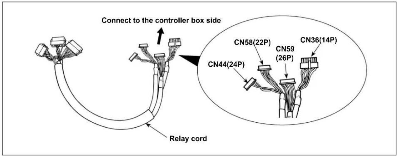
| CN36 (14P) Pin No. Function | ||
| For the head solenoid | 1 TRM Mg (-) | |
| 8 TRM Mg (+) | ||
| 7 TR Mg (-) | ||
| 14 TR Mg (+) | ||
| 10 FG | ||
| 5 BT SW | ||
| 12 GND | ||
| 4 FL SW | ||
| 11 GND | ||
| 2 WP Mg (-) | ||
| 9 WP Mg (+) | ||
| 6 BT Mg (-) | ||
| 13 BT Mg (+) | ||
| 3 | - | |
| CN58 (22P) Pin No. Function | ||
| For limiting the alter-nate vertical movement speed | 2 GND | |
| 9 +24V | ||
| 7 +12V | ||
| 14 DL Volume | ||
| 4 DL Limit SW1 | ||
| 5 DL Limit SW2 | ||
| 8 GND | ||
| 1, 3, 6, 10 to 13, 15 to 22 | - | |
| CN44 (24P) Pin No. Function | ||
| For the touch back switch asm. | 4 DL SW | |
| 5 ABT SW | ||
| 6 NU SW | ||
| 7 2P SW | ||
| 8 TC SW | ||
| 12 GND | ||
| 1, 2, 3, 9, 10, 11, 13 to 24 | - | |
| CN59 (26P) Pin No. Function | ||
| For the sole-noid valve | 11 FL | |
| 12 BT | ||
| 13 DL | ||
| 14 SS | ||
| 15 2P | ||
| 16 FL2 | ||
| 17 TRM | ||
| 18 TRM RET | ||
| 19 TC | ||
| 22 DLSW LED | ||
| 23 2PSW LED | ||
| 1 to 5 +24V | ||
| 6 to 10, 20, 21, 24, 25, 26 | - | |
10. LU-2220N-7 NEEDLE THREAD CLAMP FUNCTION
For the Needle thread clamp function, there are the functions below.
| Function | |
| Function No. 156Needle threadclamp function | 0: When the Needle thread clamp switch is turned ON, the function becomes valid.1: Needle thread clamp function becomes invalid.2: Regardless of turning ON/OFF of the Needle thread clamp switch, the function becomes valid. |
[How to make the setting]
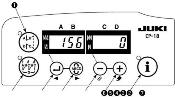
1) Refer to "1. Setting of the mounted head, 1) How to enter into the function setting mode", and enter into the function setting mode.
2) Press switch ③ or Switch ④ to call out function setting No.156.
3) Press ⏻ switch ⑤ or ⏻ switch ⑥ and select the function.
4) Press ← switch ③ or ABCD → switch ④ and return to the function setting mode.
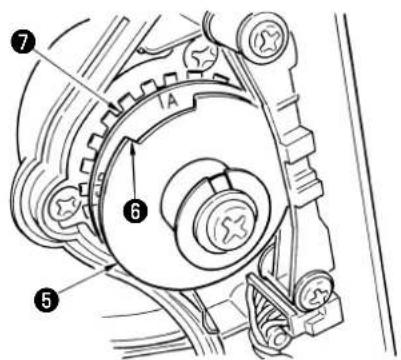
11. LU-2200N-7 SERIES THICK THREAD CUTTING
When a thick thread (equivalent to #4 or higher) is used and the thread cannot be cut, make the setting of the function described below.
| Function | |
| Function No. 143Brake starting angle of thread trimming UP stop | Brake starting angle at the time of thread trimming UP stop is set.Setting range : 0 to 10 degreesSet value at the time of delivery from factory : 0 degree |
[How to make the setting]
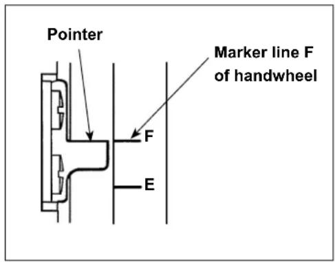
Set the UP stop position so that the pointer aligns with engraved marker line F of the handwheel.
Set the value that is set first to "7" degrees and confirm the UP stop position.
When the UP stop position exceeds engraved marker line F, decrease the set value of the undermentioned 3) by one and confirm the UP stop position.
When the UP stop position is located on this side from engraved marker line F, increase the set value of the undermentioned 3) by one and confirm the UP stop position.
Set function No.56 (Reverse needle up after thread cut function) to "0: null", cut the thread, and verify if the cutting was appropriately done.
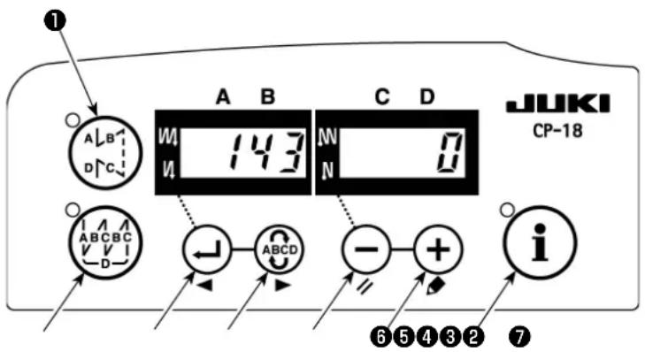
1) Refer to "1. Setting of the mounted head, 1) How to enter into the function setting mode", and enter into the function setting mode.
2) Press ← switch ③ or ABCD → switch ④ to call out function setting No.143.
3) Press ⏻ switch ⑤ or ⏻ switch ⑥ and set the angle.
4) Press ← switch ③ or and return to the function setting mode.
12. HOW TO COPE WITH THE NEEDLE BAR DOWN WHEN THE MACHINE MAKES A DOWN POSITION STOP
If the needle bar lowers when the machine made a down position stop, make the settings of the following functions.
| Functions | |
| Function No.58Needle bar normal position retaining function | Needle bar vertical normal position retaining function0 : Needle bar normal position retaining function disabled1 : Needle bar normal position retaining force – weak2 : Needle bar normal position retaining force – medium3 : Needle bar normal position retaining force – strong |
[How to make the setting]
1) Refer to "1. Setting of the mounted head, 1) How to enter into the function setting mode", and enter into the function setting mode.
2) Press ← switch ③ or ABCD switch ④ to call out function setting No. 58.
3) Press ⏻ switch ⑤ or ⏻ switch ⑥ and select the function.
4) Press ⏻ switch ③ or ⬇ Switch ④ and return to the function setting mode.
- TABLE OF SC-922 FUNCTION ITEMS IN ACCORDANCE WITH THE ADDITIONAL DEVICES
| Additional device | Function No. | Function item | Starting level | Setting range | Description | Applicable model |
| 2-pitch device | 148 2-pitch output during reverse feed stitching at start or at end | User 0, | 1 0 : Invalid | 1 : 2-pitch is output during controlling reverse feed stitching at start or end. | LU-2212N-7LU-2220N-7 | |
| 149 Inversion of 2-pitch output during outputting alternate vertical amount | User 0, | 1 0 : Invalid | 1 : State of 2-pitch output is inversely output, synchronizing with alternate vertical output. | |||
| 150 2-pitch initial output User 0, 1, 2 0 : When the power is ON, reset is made with the status of the previous power OFF.1 : When the power is ON, 2-pitch output is turned OFF.2 : When the power is ON, 2-pitch output is turned ON. | ||||||
| Alternate vertical amount change device | 144 Setting of number of stitches of automatic release of alternate vertical output | User 0, | 1 to 30 stitches | 0 : Automatic release is invalid.1 to 30 : Release of alternate vertical output is automatically performed by the number of stitches. | LU-1500N-7LU-1520NC-7LS-1342-7DNU-1541-7PLC-1700-7LU-2200N-7 | |
| 146 Selection of alternate vertical output after thread trimming | User 0, | 1, 2 0 : Invalid | 1 : Alternate vertical output is forcibly turned OFF after thread trimming.2 : Alternate vertical output is forcibly turned ON after thread trimming. | |||
| 147 Alternate vertical initial output | User 0, | 1, 2 0 : When the power is ON, reset is made with the status of the previous power OFF.1 : When the power is ON, alternate vertical output is turned OFF.2 : When the power is ON, alternate vertical output is turned ON. | ||||
| Needle thread clamp device | 156 Selection of needle thread clamp switch function | User 0, | 1, 2 0 : When the needle clamp switch is turned ON, this function is enabled.1 : Needle clamp function will be disabled.2 : Needle clamp function is enabled forcibly. | LU-2220N-7 | ||
DEUTSCH

natural_image
Technical line drawing of a mechanical component with no visible text or symbolsLU-2200N-7 (SW Typ)
2. INSTALLIEREN DES POSITIONSGEBERS


natural_image
Technical line drawing of a mechanical assembly with an arrow indicating direction (no text or symbols present)DU-141H-7 / DSC / DSU

(1) Bedienungsweise
flowchart
graph TD
    A["Normalvorschub"] --> B
    B --> C
    C --> D
    D --> E
    E --> F
    F --> G
    G --> H
    H --> I
    I --> J
    J --> K
    K --> L
    L --> M
    M --> N
    N --> O
    O --> P
    P --> Q
    Q --> R
    R --> S
    S --> T
    T --> U
    U --> V
    V --> W
    W --> X
    X --> Y
    Y --> Z
natural_image
Technical line drawing of a mechanical component with no visible text or symbolsLU-2200N-7 (Type de SW)
2. INSTALLATION DU SYNCHRONISEUR


natural_image
Technical line drawing of a mechanical assembly with an arrow indicating direction (no text or symbols present)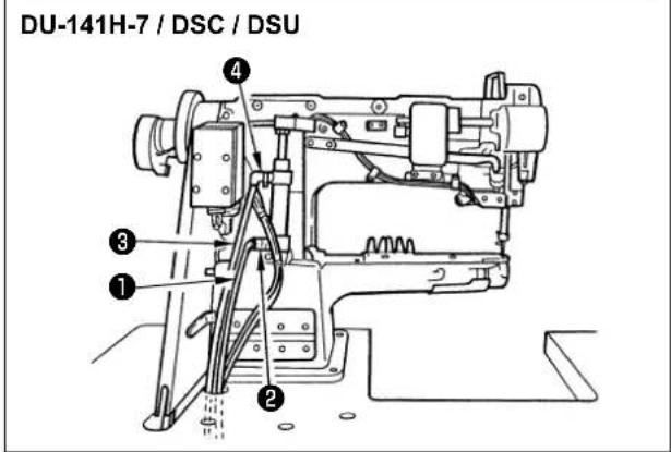

7. COUTURE MANUELLE À ENTRAÎNEMENT INVERSE PRATIQUE UNE PRESSION
natural_image
Technical line drawing of a mechanical component with no visible text or symbols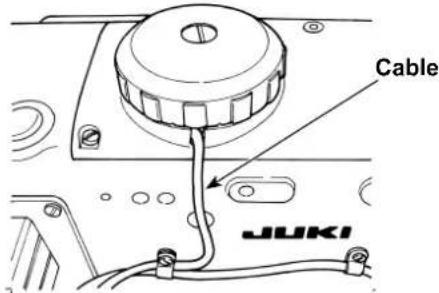


natural_image
Technical line drawing of a mechanical assembly with an arrow indicating direction (no text or symbols present)DU-141H-7 / DSC / DSU
natural_image
Pure mechanical diagram showing a lever system with pivot point and guide rails (no text or symbols)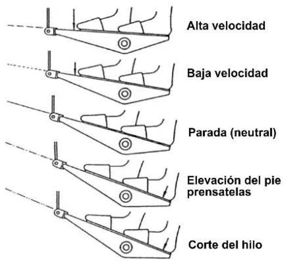
7. COSTURA PRÁCTICA DE TRANSPORTE INVERSO MANUAL DE UN TOQUE
natural_image
Technical line drawing of a mechanical component with no visible text or symbols
natural_image
Technical line drawing of a mechanical assembly with labeled components (no readable text or symbols)


natural_image
Technical line drawing of a mechanical assembly with an arrow indicating direction (no text or symbols present)
natural_image
Technical line drawing of a mechanical component with no visible text or symbolsLU-2200N-7 (SW 型号)
2. 位置检测器的安装

natural_image
Technical line drawing of a mechanical assembly with an arrow indicating direction (no text or symbols present)例如:LU-1500N-7 系列
DU-141H-7 / DSC / DSU

natural_image
Line drawing of a sewing machine with JUKI branding and labeled connection point A (no text or symbols beyond labels)
DSC
(1) 使用方法
| CN102(18P) | 引脚 No. 功能 | |
| 电磁阀用 1 | FL | |
| 2 BT | ||
| 3 DL | ||
| 4 SS | ||
| 5 2P | ||
| 6 TRM | ||
| 7 TRM RET | ||
| 8 TC | ||
| 9 FL2 | ||
| 10, 11, 12, 13, 14, 15, 16, 17, 18 | +24V |
| CN36(14P) | 引脚 No. 功能 | |
| 机头电磁阀用 | 1 TRM Mg | (-) |
| 8 TRM Mg | (+) | |
| 7 TR Mg | (-) | |
| 14 TR Mg | (+) | |
| 10 FG | ||
| 5 BT SW | ||
| 12 GND | ||
| 4 FL SW | ||
| 11 GND | ||
| 2 WP Mg | (-) | |
| 9 WP Mg | (+) | |
| 6 BT Mg | (-) | |
| 13 BT Mg | (+) | |
| 3 - |
| CN58(22P) | 引脚 No. 功能 | |
| 限制交替上下量速度用 | 2 GND | |
| 9 +24V | ||
| 7 +12V | ||
| 14 DL Volume | ||
| 4 DL Limit SW1 | ||
| 5 DL Limit SW2 | ||
| 8 GND | ||
| 1, 3, 6, 10 ~ 3,15 ~ 22 |
| CN44(24P) | 引脚 No. 功能 | |
| 触摸倒缝开关组用 | 4 DL SW | |
| 5 ABT SW | ||
| 6 NU SW | ||
| 7 2P SW | ||
| 8 TC SW | ||
| 12 GND | ||
| 1, 2, 3, 9, 10,11, 13 ~ 24 | - |
| CN59(26P) | 引脚 No. 功能 | |
| 电磁阀用 11 | FL | |
| 12 BT | ||
| 13 DL | ||
| 14 SS | ||
| 15 2P | ||
| 16 FL2 | ||
| 17 TRM | ||
| 18 TRM RET | ||
| 19 TC | ||
| 22 DLSW LED | ||
| 23 2PSW LED | ||
| 1~5 +24V | ||
| 6 ~ 10, 20, 21,24, 25, 26 | - |
SEWING MACHINERY BUSINESS UNIT
2-11-1, TSURUMAKI, TAMA-SHI,
Copyright © 2010-2016 JUKI CORPORATION
- All rights reserved throughout the world.
Please do not hesitate to contact our distributors or agents in your area for further information when necessary.
* The description covered in this instruction manual is subject to change for improvement of the commodity without notice.
- 位置検出器の取り付け
- 使い方
- CONTENTS
- SETTING OF THE MOUNTED MACHINE HEAD
- (Caution)
- INSTALLING THE SYNCHRONIZER
- ■ How to set the needle bar position when the machine is stopped
- INSTALLATION OF AK/AIR DEVICE
- WARNING :
- Installation of AK/air device
- Air hose piping
- [Example: LU-1500N-7 series]
- Installation of the knee switch
- Function setting of the knee switch
- How to use
- Adjusting the lift of the presser foot
- CONNECTING THE CORDS
- THREADING THE PANEL THREAD GUIDE
- ONE-TOUCH UTILITY MANUAL REVERSE FEED STITCHING
- How to operate
- Position of the switch
- FRONT TIE STITCHING
- RELAY CORD
- LU-2220N-7 NEEDLE THREAD CLAMP FUNCTION
- LU-2200N-7 SERIES THICK THREAD CUTTING
- HOW TO COPE WITH THE NEEDLE BAR DOWN WHEN THE MACHINE MAKES A DOWN POSITION STOP
- DEUTSCH
- INSTALLIEREN DES POSITIONSGEBERS
- Bedienungsweise
- INSTALLATION DU SYNCHRONISEUR
- COUTURE MANUELLE À ENTRAÎNEMENT INVERSE PRATIQUE UNE PRESSION
- COSTURA PRÁCTICA DE TRANSPORTE INVERSO MANUAL DE UN TOQUE
- 位置检测器的安装
- 使用方法
Brand : JUKI
Model : DNU-1541-7
Category : Sewing machine