HAHG9WL38WX/1 - Cooker HAIER - Free user manual and instructions
Find the device manual for free HAHG9WL38WX/1 HAIER in PDF.

User questions about HAHG9WL38WX/1 HAIER
0 question about this device. Answer the ones you know or ask your own.
Ask a new question about this device
Download the instructions for your Cooker in PDF format for free! Find your manual HAHG9WL38WX/1 - HAIER and take your electronic device back in hand. On this page are published all the documents necessary for the use of your device. HAHG9WL38WX/1 by HAIER.
USER MANUAL HAHG9WL38WX/1 HAIER
Thank you for having purchased and given your preference to our product.
The safety precautions and recommendations reported below are for your own safety and that of others. They will also provide a means by which to make full use of the features offered by your appliance.
Please preserve this booklet carefully. It may be useful in future, either to yourself or to others in the event that doubts should arise relating to its operation.
This appliance must be used only for the task it has explicitly been designed for, that is for cooking foodstuffs. Any other form of usage is to be considered as inappropriate and therefore dangerous.
The manufacturer declines all responsibility in the event of damage caused by improper, incorrect or illogical use of the appliance.
DECLARATION OF CE CONFORMITY
- This appliance has been designed to be used only for cooking. Any other use (such as heating a room) is improper and dangerous.
-
This appliance has been designed, constructed, and marketed in compliance with:
-
Safety requirements of the "Gas" Regulation (EU) 2016/426;
- Safety requirements of the "Low voltage" Directive 2014/35/EU;
- Safety requirements of the "EMC" Directive 2014/30/EU;
- Requirements of EU Directive 93/68/EEC;
- Requirements of EU Directive 2011/65/EU.
CE
IMPORTANT INFORMATION FOR CORRECT DISPOSAL OF THE PRODUCT IN ACCORDANCE WITH EC DIRECTIVE 2012/19/EC.
At the end of its working life, the product must not be disposed of as urban waste. It must be taken to a special local authority differentiated waste collection centre or to a dealer providing this service.
Disposing of a household appliance separately avoids possible negative consequences for the environment and health deriving from inappropriate disposal and enables the constituent materials to be recovered to obtain significant savings in energy and resources. As a reminder of the need to dispose of household appliances separately, the product is marked with a crossed-out wheeled dustbin.
natural_image
Simple line drawing of a trash bin with two crossed lines indicating no waste or prohibition (no text or symbols)
IMPORTANT SAFETY PRECAUTIONS AND RECOMMENDATIONS
IMPORTANT: This appliance is designed and manufactured solely for the cooking of domestic (household) food and is not suitable for any non domestic application and therefore should not be used in a commercial environment.
The appliance guarantee will be void if the appliance is used within a non domestic environment i.e. a semi commercial, commercial or communal environment.
Read the instructions carefully before installing and using the appliance.
- This appliance has been designed and manufactured in compliance with the applicable standards for the household cooking products and it fulfills all the safety requirements shown in this manual, including those for surface temperatures.
Some people with sensitive skin may have a more pronounced temperature perception with some components although these parts are within the limits allowed by the norms.
The complete safety of the appliance also depends on the correct use, we therefore recommend to always pay a extreme attention while using the product, especially in the presence of children.
- After having unpacked the appliance, check to ensure that it is not damaged.
In case of doubt, do not use it and consult your supplier or a professionally qualified technician.
- Packing elements (i.e. plastic bags, polystyrene foam, nails, packing straps, etc.) should not be left around within easy reach of children, as these may cause serious injuries.
- Some appliances are supplied with a protective film on steel and aluminium parts. This film must be removed before using the appliance.
- IMPORTANT: The use of suitable protective clothing/gloves is recommended when handling or cleaning this appliance.
- Do not attempt to modify the technical characteristics of the appliance as this may become dangerous to use. The manufacturer declines all responsibility for any inconvenience resulting from the inobservance of this condition.
- CAUTION: this appliance must only be installed in a permanently ventilated room in compliance with the applicable regulations.
- Do not operate your appliance by means of an external timer or separate remote-control system.
- Do not carry out cleaning or maintenance operations on the appliance without having previously disconnected it from the electric power supply.
- Do not use a steam cleaner because the moisture can get into the appliance therefore making it unsafe.
- Do not touch the appliance with wet or damp hands (or feet).
- Do not use the appliance whilst in bare feet.
- If you should decide not to use this appliance any longer (or decide to substitute another model), before disposing of it, it is recommended that it be made inoperative in an appropriate manner in accordance to health and environmental protection regulations, ensuring in particular that all potentially hazardous parts be made harmless, especially in relation to children who could play with unused appliances.
- The various components of the appliance are recyclable. Dispose of them in accordance with the regulations in force in your country. If the appliance is to be scrapped, remove the power cord.
• After use, ensure that the knobs are in the off position.
- Children less than 8 years of age shall be kept away unless continuously supervised.
- This appliance can be used by children aged from 8 years and above and persons with reduced physical, sensory or mental capabilities or lack of experience and knowledge if they have been given supervision or instruction concerning use of the appliance in a safe way and understand the hazards involved. Children shall not play with the appliance. Cleaning and user maintenance shall not be made by children without supervision.
- The manufacturer declines all liability for injury to persons or damage to property caused by incorrect or improper use of the appliance.
-
WARNING: During use the appliance and its accessible parts become hot; they remain hot for some time after use.
-
Care should be taken to avoid touching heating elements on the hob.
-
To avoid burns and scalds, young children should be kept away.
-
Make sure that electrical cables connecting other appliances in the proximity of the cooktop cannot come into contact with the hob.
- WARNING: Unattended cooking on a hob with fat or oil can be dangerous and may result in fire. NEVER try to extinguish a fire with water, but switch off the appliance and then cover flame e.g. with a lid or a fire blanket.
- WARNING: Danger of fire: do not store items on the cooking surfaces.
- WARNING: When correctly installed, your product meets all safety requirements laid down for this type of product category. However special care should be taken around the underneath of the appliance as this area is not designed or intended to be touched and may contain sharp or rough edges, that may cause injury.
- CAUTION: The cooking process has to be supervised. A short term cooking process has to be supervised continuously.
- If the power supply cable is damaged, it must be replaced only by an authorized service agent in order to avoid a hazard.
-
If the appliance is not fitted with a supply cord and a plug, or with other means for disconnection from the supply mains having a contact separation in all poles that provide full disconnection under overvoltage category III conditions, means for disconnection must be incorporated in the fixed wiring in accordance with the wiring rules.
-
WARNING: The appliance and its accessible parts become hot during use. Care should be taken to avoid touching heating elements. Children less than 8 years of age shall be kept away unless continuously supervised.
- WARNING: Use only hob guards designed by the manufacturer of the cooking appliance or indicated by the manufacturer of the appliance in the instructions for use as suitable or hob guards incorporated in the appliance. The use of inappropriate guards can cause accidents.
ENERGY LABELLING/ECODESIGN
- Commission regulation (EU) No 66/2014 (implementing Directive 2009/125/EC of the European Parliament and of the Council).
Reference to the measurement and calculation methods used to establish compliance with the above requirements:
- Standard EN30-2-1 (hobs: gas fired burners).
USE OF THE APPLIANCE, ENERGY SAVING TIPS
HOB
GAS FIRED BURNERS
- It is important that the diameter of the pot be suitable to the size of the burner so as not to compromise the high output of the burners and therefore energy waste. A small pot on a large burner does not give you a boiling point in a shorter amount of time since the capacity of heat absorption of a liquid mass depends on the volume and the surface of the pot.
- Avoid keeping a burner on without something on it (without pot).
ADVICE ADVIC for the for the INSTALLER INST1
IMPORTANT:
- The appliance is designed and approved for domestic use only and should not be installed in a commercial, semi commercial or communal environment.
Your product will not be guaranteed if installed in any of the above environments and could affect any third party or public liability insurances you may have.
- This appliance is to be installed, regulated and adapted to function only by an authorised person in compliance with the current local regulations in force and in observation of the instructions supplied by the manufacturer.
Failure to comply with this condition will render the guarantee invalid.
- The appliance must be installed in compliance with regulations in force in your country and in observation of the manufacturer's instructions.
- Installation technicians must comply to current laws in force concerning ventilation and the evacuation of exhaust gases.
- Incorrect installation, for which the manufacturer accepts no responsibility, may cause personal injury or damage.
- This appliance shall only be serviced by authorised personnel.
- Always disconnect the appliance from mains power supply before carrying out any maintenance operations or repairs.
- Important: The use of suitable protective clothing/gloves is recommended when handling or cleaning of this appliance.
- These tops are designed to be embedded into kitchen fixtures measuring 600 mm in depth, working surface 30 to 40 mm thick.
- The appliance must be housed in heat-resistant units.
- The walls of the units must not be higher than work top and must be capable of resisting temperatures of 70^ above room temperature.
- We would point out that the adhesive which bonds the plastic laminate to the furniture must withstand temperatures not less than 150^ to avoid delamination.
- Do not install the appliance near inflammable materials (eg. curtains).
WARNING!
When correctly installed, your product meets all safety requirements laid down for this type of product category. However special care should be taken around the underneath of the appliance as this area is not designed or intended to be touched and may contain sharp or rough edges, that may cause injury.
1 INSTALLATION
TECHNICAL INFORMATION FOR THE INSTALLER
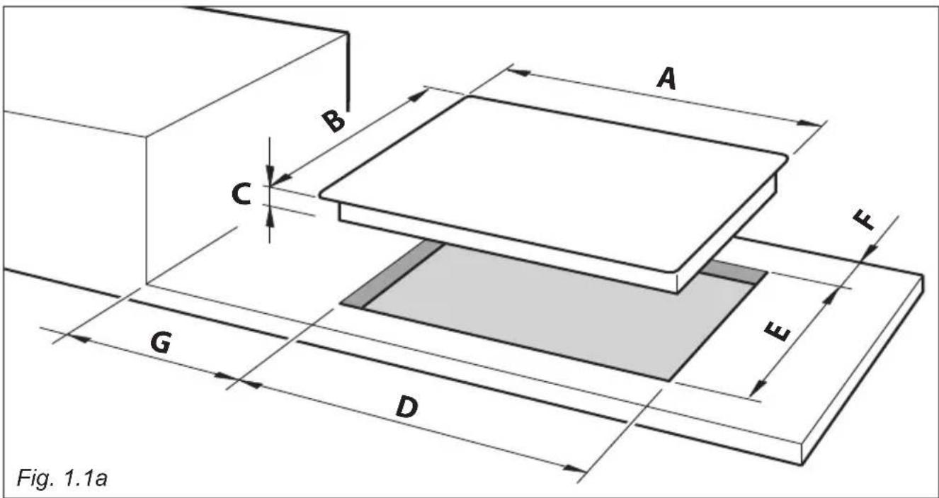
In order to install the cooker top into the kitchen fixture, a hole with the dimensions shown in fig. 1.1a has to be made, bearing in mind the following:
- A 40 mm ventilation gap must be provided between the bottom of the appliance and any cabinetry, draw unit, thermal protection barrier.
- If the base of the cooktop is accessible through a cupboard or drawer space after installation, a thermal protection barrier must be installed below the base of the cooktop as indicated in fig. 1.1c.
- The cooker top must be kept no less than 200 mm away from any side wall (from side edge of cutout - figs. 1.1a, 1.1b).
- The hob must be installed at least 60 mm from the wall (from rear edge of cutout - fig. 1.1a).
- There must be a distance of at least 650 mm between the hob and any wall cupboard or extractor hood positioned immediately above (see fig. 1.1b).
text_image
Fig. 1.1a A B C G D E E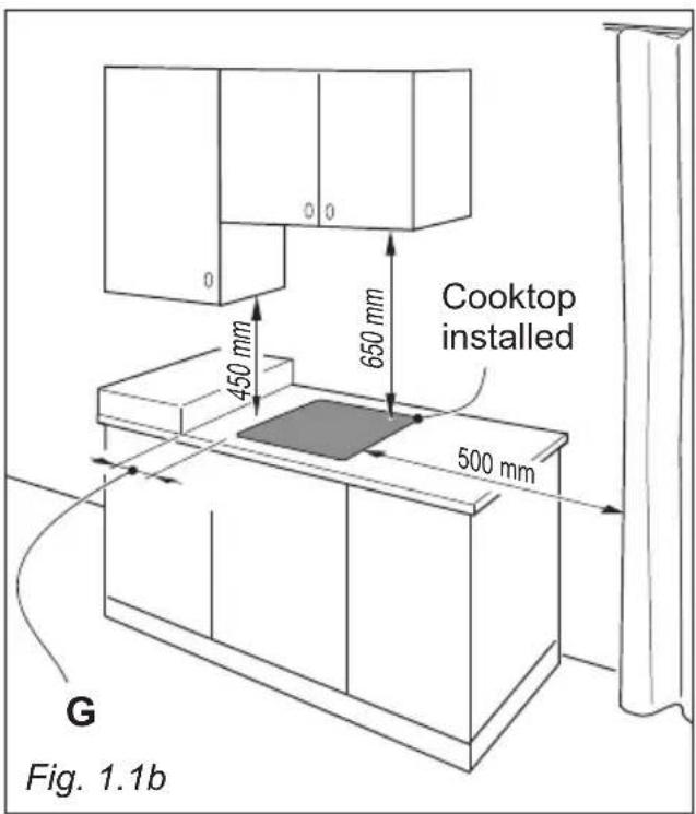
text_image
Cooktop installed 450 mm 650 mm 500 mm G Fig. 1.1b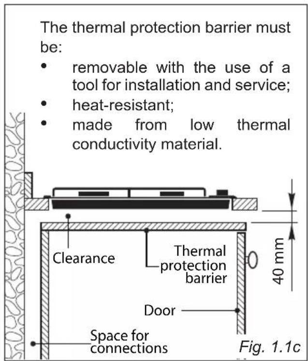
text_image
The thermal protection barrier must be: • removable with the use of a tool for installation and service; • heat-resistant; • made from low thermal conductivity material. Clearance Thermal protection barrier Door Space for connections 40 mm Fig. 1.1c| Measures (mm) | |||||||
| Description A B | C D E F | (minimum) | G (minimum) | ||||
| 90cm wide models | 900 510 | 49 840 | 480 60 | 200 | |||
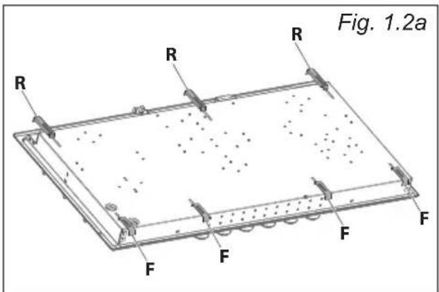
FASTENING THE COOKTOP
Each cooktop is provided with an installation kit including brackets and screws for fastening the cooktop to benches from 30 to 40 mm thick.
The kit includes four "F" type brackets (for the front of the cooktop), three "R" type brackets (for the rear of the cooktop) and seven self-threading screws "S".
- Cut the unit according to the dimensions in fig. 1.1a.
- Stretch gasket "G" over the edge of the hole made, being careful to overlay the junction edges.
- Fasten the brackets "F" and "R" to the appropriate socket holes, without tightening the screws "S" for the moment. Make sure that the tabs are mounted correctly, as shown (figs. 1.2b, 1.2c). Rotate the tabs so that the cooktop can be put into the cutout.
- Put the cooktop into the cutout and position it correctly.
- Put the brackets "F" and "R" into place; tooth "A" of the brackets should go into the hole (figs. 1.2b, 1.2c).
- Tighten screws "S" until the cooktop is completely secured to the bench.
- Using a sharp cutter or trimmer knife, trim the excess sealing material around the edge of the cooktop.
Take care not to damage the workbench.
text_image
Fig. 1.2a R R R F F F F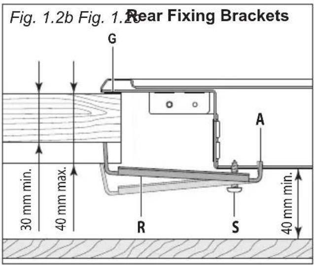
text_image
Fig. 1.2b Fig. 1.2 Rear Fixing Brackets G A 30 mm min. 40 mm max. R S 40 mm min.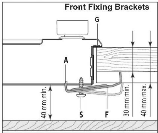
text_image
Front Fixing Brackets G A S F 30 mm min. 40 mm min. 40 mm max.VENTILATION REQUIREMENTS
The appliance must be installed in compliance with applicable local regulations concerning ventilation and the evacuation of exhaust gases.
Intensive and prolonged use may require extra ventilation, e.g. opening a window, or more efficient ventilation increasing the mechanical suction power if this is fitted.
The room where the gas appliance is to be installed must have a natural flow of air so that the gas can burn (in compliance with applicable local regulations).
The flow of air must come directly from one or more openings made in the outside walls with a free area of at least 100cm^2 (or refer to applicable local regulations).
The openings should be near the floor and preferably on the side opposite the exhaust for combustion products and must be made so that they cannot be blocked from either the inside or the outside.
When these openings cannot be made, the necessary air can come from an adjacent room which is ventilated as required, as long as it is not a bed room or a danger area (in compliance with applicable local regulations).
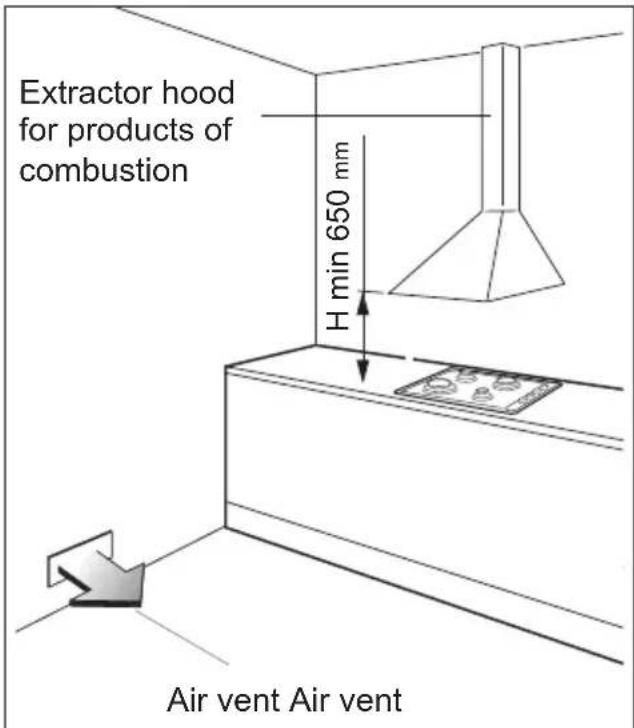
In this case, the kitchen door must allow the passage of the air. There must be a distance of at least 650mm between the hob of the cooker and any wall cupboard or extractor hood positioned immediately above (see fig. 1.3).
DISCHARGING PRODUCTS OF COMBUSTION
Extractor hoods connected directly to the outside must be provided, to allow the products of combustion of the gas appliance to be discharged (fig. 1.3).
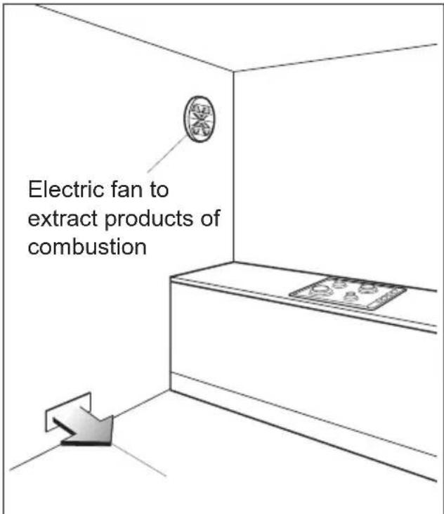
If this is not possible, an electric fan may be used, attached to the external wall or the window; the fan should have a capacity to circulate air at an hourly rate of 3-5 times the total volume of the kitchen (fig. 1.4).
The fan can only be installed if the room has suitable vents to allow air to enter, as described under the heading "Choosing suitable surroundings".
text_image
Extractor hood for products of combustion H min 650 mm Air vent Air ventFig. 1.3
text_image
Electric fan to extract products of combustionFig. 1.4
GAS INSTALLATION REQUIREMENTS
Important!
- This appliance must be installed and serviced only by a suitably qualified, registered installer. The installer shall refer to the local standards in force.
- Failure to install the appliance correctly could invalidate any manufacturer's warranty.
- Before installation, make sure that the local distribution conditions (gas type and pressure) and the adjustment of this appliance are compatible. The appliance adjustment conditions are given on the plate or the label.
- If the gas pressure (for which the appliance is to be used) is variable or if it is not within the values indicated on the rating plate, it is mandatory to install a proper gas pressure regulator which must be adjusted to guarantee the correct operating pressure to the appliance (as per rating plate).
The regulator must be installed, adjusted and tested by a qualified technician.
- WARNING: Using the appliance with a wrong and/or variable gas pressure may be extremely dangerous and may result in serious injury to the user. Damage to the appliance could occur if not observing this condition.
The manufacturer declines every responsibility for any inconvenience resulting from the inobservance of this condition.
This appliance is supplied for use on LPG (check the gas regulation label attached on the appliance).
OR
This appliance is supplied for use on Natural gas or LPG (check the gas regulation label attached on the appliance).
- Appliances supplied for use on Natural gas: they are adjusted for this gas only and cannot be used on any other gas (LPG) without modification. The appliances are manufactured for conversion to LPG.
- Appliances supplied for use on LPG: they are adjusted for this gas only and cannot be used on any other gas (Natural gas) without modification. The appliances are manufactured for conversion to Natural gas.
If the Natural gas/LPG conversion kit is not supplied with the appliance this kit can be purchased by contacting the After-Sales Service.
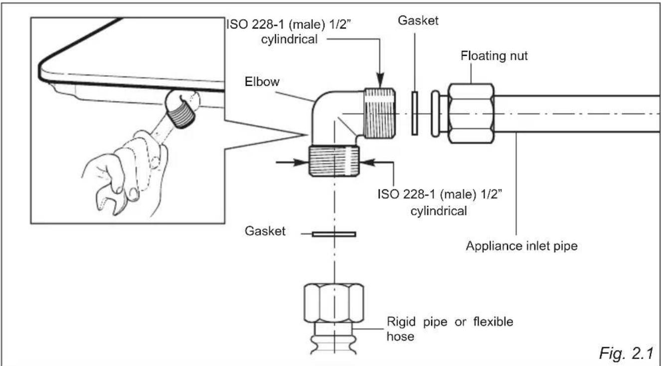
CONNECTING THE COOKTOP TO THE GAS SUPPLY
The gas connection fitting (fig. 2.1) is made up of:
- the floating nut;
- the elbow;
- the gaskets;
The gas connection must be carried out by an authorised person according to the relevant local standards.
- If using a flexible hose, make sure it does not come into contact with moving parts.
- The rear of the chassis is recessed to provide a channel for the appliance inlet pipe.
- The gas connection fitting can be turned in the direction required (but never in a vertical or horizontal position) after loosening the elbow and floating nut connection.
- Never attempt to turn the elbow without having first loosened the floating nut.
- The supplied gaskets guarantee a good seal for the gas connection. We recommend that you replace the gaskets on the slightest sign of wear, deformation or imperfection.
• After connecting to the gas mains, check that the couplings are correctly sealed, using soapy solution, but never a naked flame.
text_image
ISO 228-1 (male) 1/2" cylindrical Gasket Elbow Floating nut ISO 228-1 (male) 1/2" cylindrical Appliance inlet pipe Gasket Rigid pipe or flexible hose Fig. 2.1ADDITIONAL GAS CONNECTION REQUIREMENTS
When connecting the cooktop to the gas supply with rigid pipes or a flexible hose, make sure that:
- You use rigid pipes or a flexible hose compliant with applicable local regulations. The flexible hose shall be of the correct construction for the type of gas being used and of the correct size to maintain the heat output of the appliance.
- The connection with rigid metal pipes does not cause stress or pressure to the gas piping.
- The flexible hose is not under tension, twisted, kinked, or too tightly bent, neither while the cooktop is in use nor while it is being connected or disconnected.
- The flexible hose is not longer than 2000 mm (or refer to applicable local regulations) and does not come into contact with sharp edges, corners, or moving parts, as these may cause abrasion. Use a single flexible hose only; never connect the cooktop with more than one flexible hose.
- The flexible hose can easily be inspected along its entire length to check its condition; if it has an expiry date, it should be replaced before that date.
- If using a flexible hose which is not entirely made of metal, make sure that it does not come into contact with any part of the cooktop with a surface temperature of 70^ or above (or refer to applicable local regulations).
- The rigid pipe or flexible hose is replaced if it shows signs of damage.
- The flexible hose is not subject to excessive heat by direct exposure to flue products or by contact with hot surfaces.
- The socket into which the plug of the flexible hose fit is permanently attached to a firmly fixed gas installation pipe and is positioned so that the hose hangs freely downwards.
- The plug of the flexible hose is accessible after installation, so that it can be disconnected for service or removal.
- You inform the customer that the rigid pipe or flexible hose should not be subjected to corrosion by cleaning agents.
GAS MAINTENANCE
Some models - for the gas category check the data label attached on the appliance
| TABLE FOR THE CHOICE OF THE INJECTORS | |||
| Cat: I 3+ | G30/G3128-30/37 mbar | ||
| BURNERS | Nominal Power [kW] | Reduced Power [kW] | ∅ injector[1/100 mm] |
| Auxiliary (A) 1,00 0,40 50 | |||
| Semi-rapid (SR) 1,75 0,45 66 | |||
| Rapid (R) 3,00 0,75 87 | |||
| Double-ring (DR) 3,80 1,50 98 | |||
| Dual (DB) - inner crown 0,80 0,40 46 | |||
| Dual (DB) - outer crown 3,40 1,50 | 65 (x2) | ||
Some models - for the gas category check the data label attached on the appliance
| TABLE FOR THE CHOICE OF THE INJECTORS | ||||
| Cat: II 2H 3+(Countries IT-ES-PT-IE-GB-GR-CH) | G30/G3128-30/37 mbar | G2020 mbar | ||
| Cat: II 2E+3+(Countries FR-BE) | G30/G3128-30/37 mbar | G20/G2520/25 mbar | ||
| Cat: II 2H3B/P(Countries DK-FI-SE-RO) | G30/G3130/30 mbar | G2020 mbar | ||
| BURNERS | Nominal Power [kW] | Reduced Power [kW] | ∅ injector[1/100 mm] | ∅ injector[1/100 mm] |
| Auxiliary (A) 1,00 0,40 50 77 | ||||
| Semi-rapid (SR) 1,75 0,45 66 101 | ||||
| Rapid (R) 3,00 0,75 87 129 | ||||
| Double-ring (DR) 3,80 1,50 98 141 | ||||
| Dual (DB) - inner crown 0,80 0,40 46 70 | ||||
| Dual (DB) - outer crown 3,40 1,50 65 (x2) 95 (x2) | ||||
| AIR VENT NECESSARY FOR GAS COMBUSTION = (2 m3/h x kW) | |
| BURNERS Air necessary for combustion [m 3/h] | |
| Auxiliary (A) | 2,00 |
| Semi-rapid (SR) | 3,50 |
| Rapid (R) | 6,00 |
| Double-ring (DR) | 7,60 |
| Dual (DB) - inner crown only | 1,60 |
| Dual (DB) - outer crown only | 6,80 |
| Dual (DB) - inner & outer crown | 8,40 |
LUBRICATION OF THE GAS TAPS
In case of difficulty in the gas taps operation, call Service.
IMPORTANT
All intervention regarding installation, maintenance and conversion of the appliance must be fulfilled with original factory parts.
The manufacturer declines any liability resulting from the non-compliance of this obligation.
REPLACEMENT OF THE INJECTORS
If the injectors are not supplied they can be obtained from the "Service Centre".
Select the injectors to be replaced according to the "TABLE FOR THE CHOICE OF THE INJECTORS".
The nozzle diameters, expressed in hundredths of a millimeter, are marked on the body of each injector.
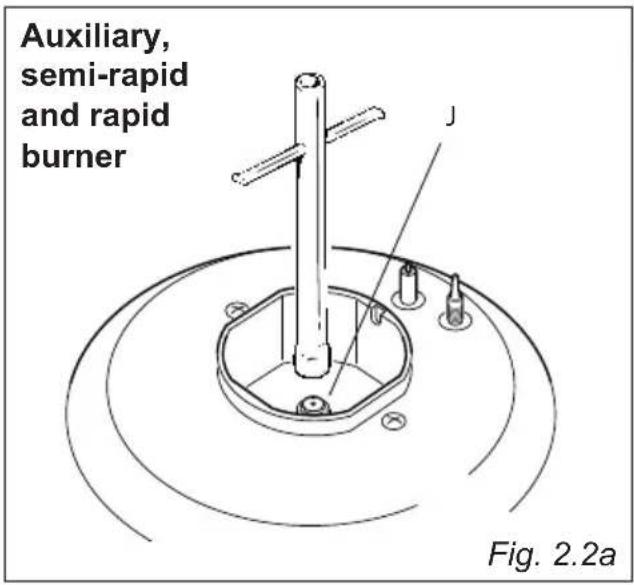
REPLACEMENT OF THE INJECTORS OF THE COOKTOP BURNERS
To replace the injectors proceed as follows:
- Remove pan supports and burners from the cooktop.
- Using a wrench, substitute the injectors "J" (figs. 2.2a, 2.2b, 2.2c) with those most suitable for the kind of gas for which it is to be used.
The burners are conceived in such a way so as not to require the regulation of the primary air.
text_image
Auxiliary, semi-rapid and rapid burner Fig. 2.2a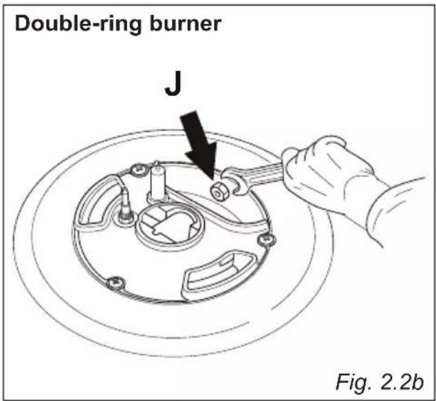
text_image
Double-ring burner J Fig. 2.2b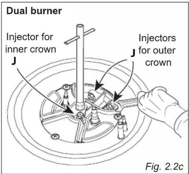
text_image
Dual burner Injector for inner crown Injectors for outer crown Fig. 2.2cSETTING THE MINIMUM OF THE COOKTOP BURNERS
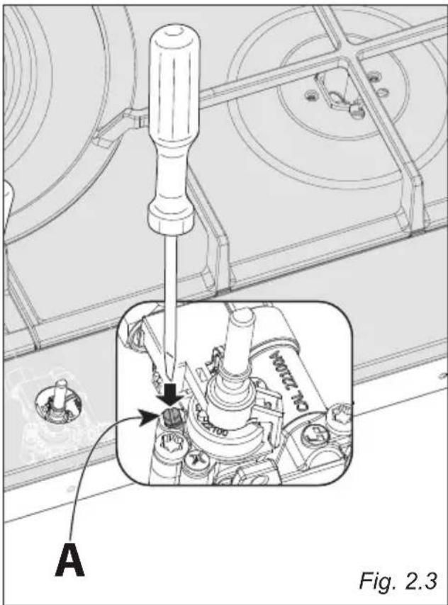
In the minimum position the flame must have a length of about 4 mm and must remain lit even with a quick turn from the maximum position to that of minimum.
The flame adjustment is done in the following way:
- Turn on the burner.
- Turn the tap to the 'MINIMUM' position.
• Take off the knob. - With a small flat screwdriver turn the screw "A" to the correct regulation (fig. 2.3).
- Models with dual burner: For the dual burner set the minimum (as indicated above) for both the gas valves (one for the inner and one for the outer crown). The operations must be carried out one gas valve at a time.
Normally for LPG tighten up the regulation screw.
text_image
A Fig. 2.3IMPORTANT: The appliance must be installed by a qualified technician according with the current local regulations and in compliance with the manufacturer instructions. Incorrect installation might cause harm and damage to people, animals or objects, for which the manufacturer accepts no responsibility.
Connection to a good earth wiring system is absolutely essential. The manufacturer accepts no responsibility for any inconvenience caused by failure to comply with this rule.
Before carrying out any work on the electrical section of the appliance, it must be disconnected from the mains.
GENERAL
- Connection to the electric power supply must be carried out by a qualified technician and following the appropriate safety regulations.
- The appliance must be connected to the mains checking that the voltage corresponds to the value given in the rating plate and that the electrical cable sections can withstand the load specified on the plate.
- If the hob is supplied without plug, fit a standard plug which is suitable for the power absorbed by the appliance and in conformity with the local rules in force.
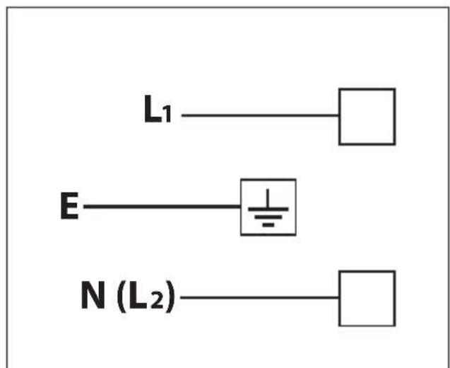
- The colours of the wires in the appliance power cable may not correspond with the colours marked on the terminals of your electrical plug. The plug should always be wired as follows:
- connect the green/yellow wire to the terminal marked with the letter "E" or the earth symbol " 1= or coloured green/yellow;
- connect the blue wire to the terminal marked with the letter "N" or coloured black;
-
connect the brown wire to the terminal marked with the letter "L" or coloured red.
-
The plug must be connected to an outlet connected to the grounding unit in conformity to security norms.
- If the appliance is to be connected directly to the mains, it must be placed with an omnipolar switch with minimum opening between the contacts of 3 mm between the appliance and the mains.
- The power supply cable must not touch the hot parts and must be positioned so that it does not exceed 50°C above ambient.
- Once the appliance has been installed, the power switch or power plug must always be in a accessible position.
- If the power supply cable is damaged it must be substituted by a suitable cable available in the after sales service.
- The appliance must have its own supply; any other appliances installed near it must be supplied separately.
– N.B. For connection to the mains, do not use adapters, reducers or branching devices as they can cause overheating and burning.
- If the hob surface is cracked disconnect the appliance from the mains and contact the After-Sales Service.
In the event that installation should require modifications to the mains supply wiring system, it is recommended that a qualified technician be called to carry out substitution.
The technician will also have to verify that the cross-section of the electric cables on the power point match the appliance's power rating.
SECTION OF THE SUPPLY CABLE TYPE "H05V2V2-F" resistant to temperatures of 90°C
220-240 V
50-60 Hz
3 × 0.75 mm
2 (*) (***)
(*) Connection possible with plug and outlet (**) Connection with wall box connection.
REPLACING THER POWER SUPPLY CABLE
WARNING: If the power supply cable is damaged, it must be replaced only by an authorized service agent in order to avoid a hazard.
To connect the supply cable:
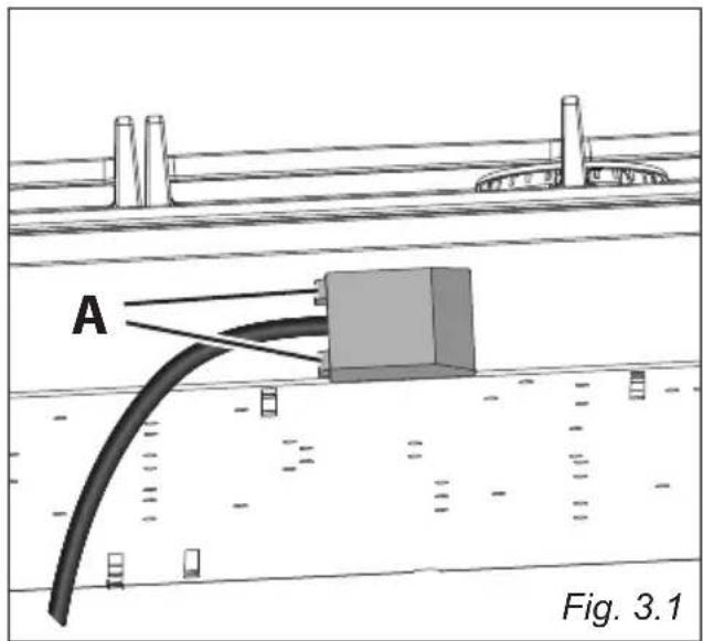
- Unhook the terminal board cover by inserting a screwdriver into the two hooks "A" (fig. 3.1).
- Open the cable gland by unscrewing screw "F" (fig. 3.2), unscrew the terminal screws and remove the cable.
- The new supply cable, of suitable type and section, must be connected to the terminal board following the diagram in fig. 3.3.
- Close and hook again the terminal board cover.
NOTE: The earth conductor must be left about 3 cm longer than the others.
The operations must be executed by a qualified technician.
text_image
A Fig. 3.1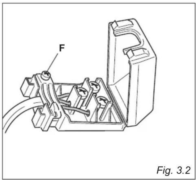
natural_image
Technical line drawing of a mechanical assembly with labeled component 'F', no readable text or symbols beyond label and figure label (Fig. 3.2)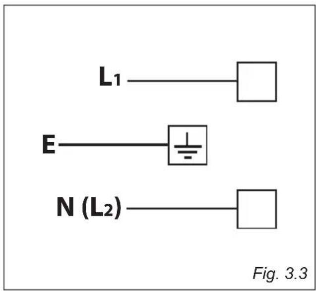
text_image
L₁ E N (L₂) Fig. 3.3ADVICE ADVIC for the for the USERS USERS
Fig. 1.1
text_image
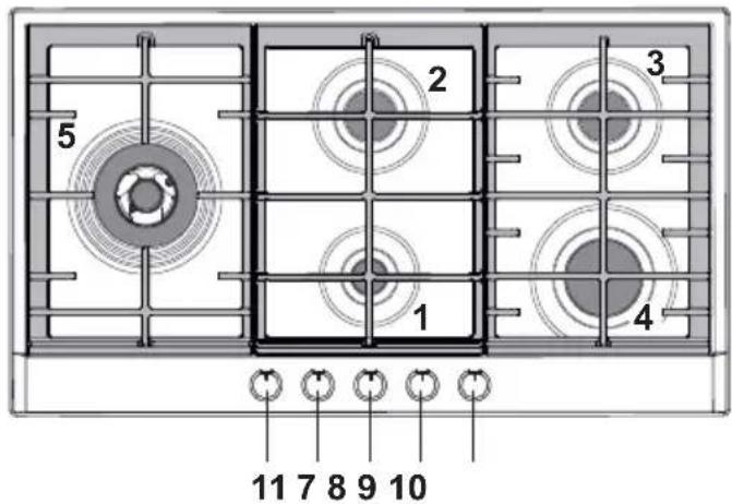
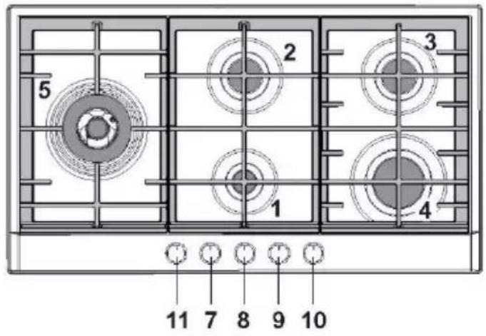
5 2 3 1 4 11 7 8 9 10Fig. 1.2
text_image
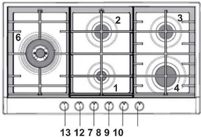
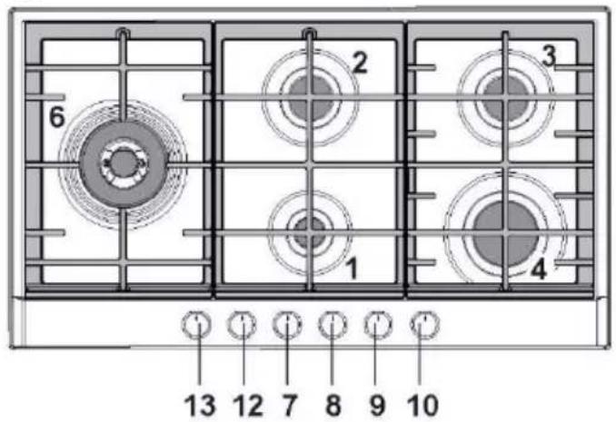
6 2 3 1 4 13 12 7 8 9 10NOTE: The knob and symbols may vary.
Caution! Do not cover the hob with aluminium foils.
GAS BURNERS
- Auxiliary (A) 1,00 kW
- Semirapid (SR) 1,75 kW
- Semirapid (SR) 1,75 kW
- Rapid (R) 3,00 kW
- Double-ring (DR) 3,80 kW
- Dual (DB) (*) 4,20 kW
(*) IMPORTANT: The Dual burner is controlled by two separate knobs; one knob for the inner crown only and one knob for the outer crown only.
The inner and outer crown can be used together or separately.
After using the dual burner check both the control knobs are in the closed “●” position.
CONTROLS DESCRIPTION
- Burner control knob (1)
- Burner control knob (2)
- Burner control knob (3)
- Burner control knob (4)
- Burner control knob (5)
- Burner control knob (6), inner crown
- Burner control knob (6), outer crown
NOTES:
• The electric ignition is incorporated in the knobs.
- The appliance has a safety valve system fitted, the flow of gas will be stopped if and when the flame should accidentally go out.
CAUTION:
If the burner is accidentally extinguished, turn the gas off at the control knob and wait at least 1 minute before attempting to relight.
CAUTION:
Gas hobs produce heat and humidity in the environment in which they are installed.
Ensure that the cooking area is well ventilated by opening the natural ventilation grilles or by installing an extractor hood connected to an outlet duct.
CAUTION:
If the hob is used for a prolonged time it may be necessary to provide further ventilation by opening a window or by increasing the suction power of the extractor hood (if fitted).
GAS BURNERS
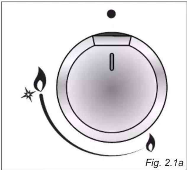
Gas flow to the burners is adjusted by turning the knobs (illustrated in fig. 2.1a or 2.1b) which control the safety valves.
Turning the knob, so that the indicator line points to the symbols printed on the panel, achieves the following functions:
- symbol closed valve
- symbol
maximum aperture or flow
- symbol
minimum aperture or flow
■ The maximum aperture position permits rapid boiling of liquids, whereas the minimum aperture position allows slower warming of food or maintaining boiling conditions of liquids.
■ To reduce the gas flow to minimum rotate the knob further anti-clockwise to point the indicator towards the small flame symbol.
■ Other intermediate operating adjustments can be achieved by positioning the indicator between the maximum and minimum aperture positions, and never between the maximum aperture and closed positions.
natural_image
Diagram of a circular object with flame-like motion arrows and a label 'Fig. 2.1a' (no readable text or symbols)
text_image
9 8 7 6 5 4 3 2 1 1 Fig. 2.1bNOTE:
The knob and symbols may vary.
Caution!
Do not cover the hob with aluminium foils.
N.B. When the cooktop is not being used, set the gas knobs to their closed positions and also close the cock valve on the gas bottle or the main gas supply line.
Caution!
The cooking hob becomes very hot during operation.
Keep children well out of reach.
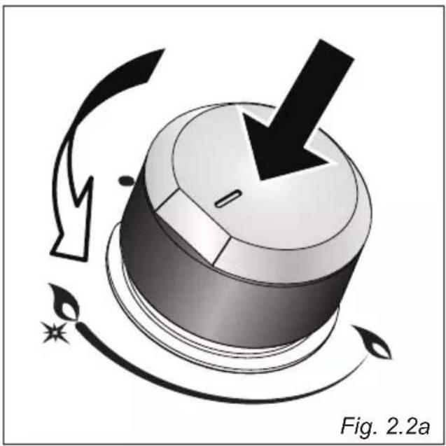
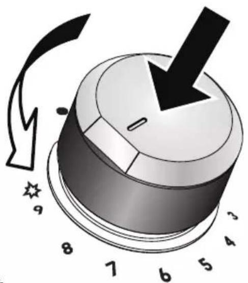
To ignite the burner, the following instructions are to be followed:
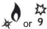
- Press in the corresponding knob and turn counter-clockwise (fig. 2.2a or 2.2b) to the full flame position marked by the “ ^6 ” or “ ^9 ” symbol; hold the knob in until the flame has been lit.
In the case of a mains failure light the burner with a match or lighted taper. - Wait for a few seconds after the gas burner has been lit before letting go of the knob (valve activation delay).
- Adjust the gas valve to the desired position.
If the burner flame should go out for some reason, the safety valve will automatically stop the gas flow.
To re-light the burner, return the knob to the closed "● position, wait for at least
1 minute and then repeat the lighting procedure.
Note: If your local gas supply makes it difficult to light the burner with the knob set to maximum, set the knob to minimum and repeat the operation.
DUAL BURNER - SOME MODELS ONLY
The Dual Burner is a very flexible burner which allows different regulations and optimal cooking.
It is composed by one inner and one outer crown: the inner and outer crown can be used together or separately.
The Dual burner is controlled by two separate knobs:
■ one knob for the inner crown only (“○” symbol identifying the control knob);
■ one knob for the outer crown only ("○" symbol identifying the control knob).
The Dual burner can be used:
■ as a small burner (flame produced only by the inner crown);
■ as a Ultra-rapid burner (flame produced only by the outer crown);
■ as a high-power burner (all flames produced simultaneously by inner and outer crown).
IMPORTANT: After using the dual burner check both the control knobs are in the closed “●” position.
natural_image
Illustration of a mechanical knob with directional arrows and starburst symbol (no text or labels)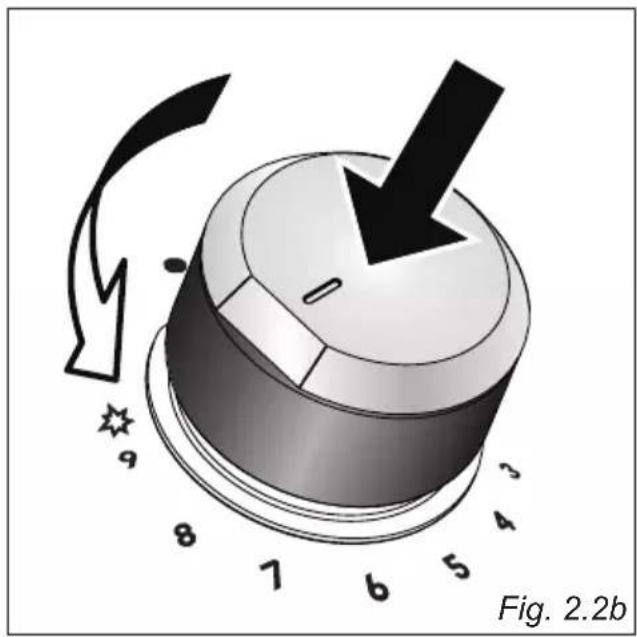
text_image
Fig. 2.2bCHOICE OF THE BURNER
On the control panel, near every knob there is a diagram that indicates which burner is controlled by that knob.
The suitable burner must be chosen according to the diameter and the capacity used.
The burners and pans must be used in accordance with the following instructions:
| DIAMETERS OF PANS WHICH MAY BE USED ON THE BURNERS | |
| BURNERS MINIMUM MAXIMUM | |
| Auxiliary 6 cm 14 cm | |
| Semi-rapid 16 cm 24 cm | |
| Rapid 24 cm 26 cm | |
| Double-ring 26 cm 28 cm | |
| Dual (inner crown only) 20 cm 24 cm | |
| Dual (outer crown only) 26 cm 28 cm | |
| Dual (inner+outer crown) | 26 cm 28 cm |
| Wok (**) - Max 36 cm | |
| do not use pans with concave or convex bases | |
(**) only for the models with Double-ring or Dual burner and with wok pan adapter supplied
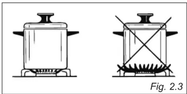
It is important that the diameter of the pot be suitable to the potentiality of the burner so as not to compromise the high output of the burners and therefore energy waste.
A small pot on a large burner does not give you a boiling point in a shorter amount of time since the capacity of heat absorption of a liquid mass depends on the volume and the surface of the pot. Too large a pot can cause damage to the burner and surrounding hob area.
CAUTION: Make sure the pans are central to the burner for maximum stability and greater efficiency.
Make sure the pans are not in contact with the control knobs, otherwise the flame could overheat the knobs and permanently damage them.
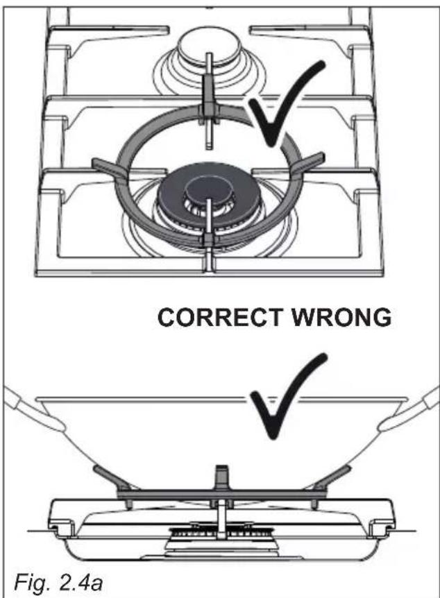
WOK STAND (OPTIONAL)
(figs. 2.4a - 2.4b)
This special grille for woks should be placed over the pan-rest for the double ring or Dual burner (depending on models).
Warning:
• Using woks without this special grille may cause the burner to malfunction.
- Do not use the grille for ordinary, flat-bottomed saucepans.
IMPORTANT:
The special grille for wok pans MUST BE PLACED ONLY over the pan-rest for the double-ring or Dual burner (depending on models).
text_image
CORRECT WRONG Fig. 2.4a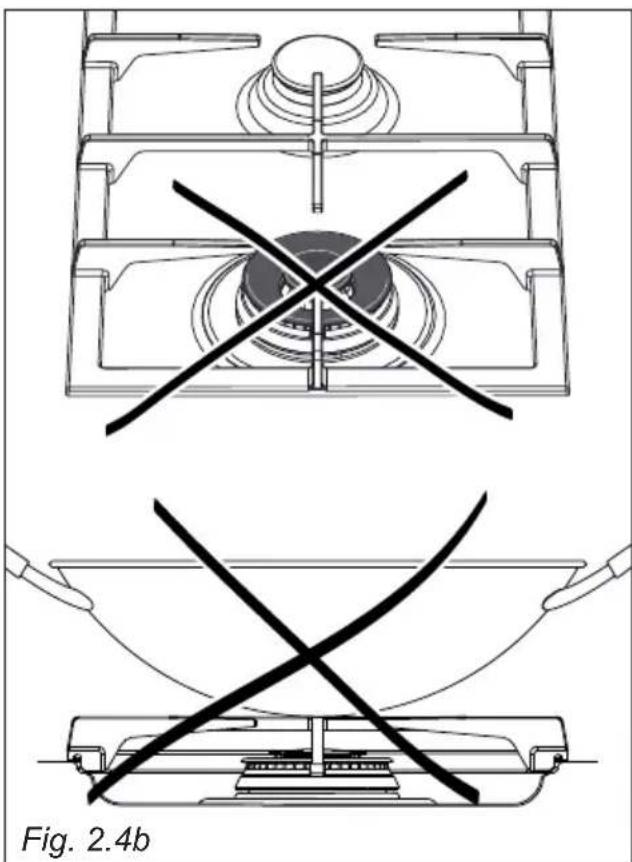
natural_image
Technical line drawings of a mechanical component with cross-sectional and top views, labeled Fig. 2.4b (no text or symbols on the diagram itself)GENERAL ADVICE
- Before you begin cleaning, you must ensure that the appliance is switched off and disconnected from the electrical power supply.
- Important: The use of suitable protective clothing/gloves is recommended when handling or cleaning of this appliance.
• Under no circumstances should any external covers be removed for servicing or maintenance except by suitable qualified personnel. - It is advisable to clean when the appliance is cold and especially when cleaning the enamelled parts.
- Be very careful that no water penetrates inside the appliance.
- Avoid leaving alkaline or acidic substances (lemon juice, vinegar, etc.) on the surfaces.
- Avoid using cleaning products with a chlorine or acidic base.
- Clean the surfaces with a damp cloth and using neutral, non-aggressive detergents. Complete the cleaning with a dry, clean cloth.
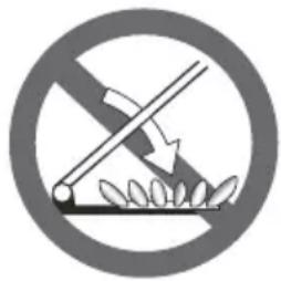
COOKING HOBS WITH GLASS LID (optional)
natural_image
Prohibition sign showing a crossed-out fence with leaves, enclosed in a circle (no text or symbols)Do not shut lid when burner alight.
ATTENTION
√ Do not lower the glass lid when the gas burner are still hot and when the oven, installed below the cooking hob, is on or still hot.
√ Do not lay on the glass lid hot pans and heavy kitchen utensils.
√ Dry off any liquid which may have spilt on the cover before opening it.
IMPORTANT: Never use abrasive
products (e.g. certain type of sponges) and/or aggressive products (e.g. caustic soda, detergents containing corrosive substances) that could irreversibly damage the surfaces.
WARNING! When correctly installed, your product meets all safety requirements laid down for this type of product category. However special care should be taken around the underneath of the appliance as this area is not designed or intended to be touched and may contain sharp or rough edges, that may cause injury.
GLASS CONTROL PANEL (some models only)
Clean using an appropriate product. Always dry thoroughly.
Do not use harsh abrasive cleaners or sharp metal scrapers to clean the control panel since they can scratch the surface, which may result in shattering of the glass.
Important: The manufacturer declines all liability for possible damage caused by the use of unsuitable products to clean the appliance.
Attention! The appliance gets very hot, mainly around the cooking areas. It is very important that children are not left alone in the kitchen when you are cooking.
Do not use a steam cleaner because the moisture can get into the appliance thus make it unsafe.
ENAMELLED SURFACES
All the enamelled parts must be cleaned with a sponge and soapy water only or other non-abrasive products. Dry preferably with a microfibre or soft cloth.
If acid substances such as lemon juice, tomato conserve, vinegar etc. are left on the enamel for a long time they will etch it, making it opaque.
STAINLESS STEEL SURFACES
Stainless steel parts must be rinsed with water and dried with a soft and clean cloth. For persistent dirt, use specific non-abrasive products available commercially or a little hot vinegar.
PAINTED PARTS AND SILKSCREEN PRINTED SURFACES
Clean using an appropriate product. Always dry thoroughly.
IMPORTANT: these parts must be cleaned very carefully to avoid scratching and abrasion.
You are advised to use a soft cloth and neutral soap.
CAUTION: Do not use abrasive substances or non-neutral detergents as these will irreparably damage the surface.
Note: Continuous use may cause a change in the glaze around the burners, corresponding to the areas exposed to the heat.
GAS TAPS
- Do not let cleaning products come into contact with the valves.
- Periodic lubrication of the gas taps must be carried out by specialist personnel only.
- In the event of operating faults in the gas taps, call the Service Department.
BURNERS
These parts must be cleaned using a sponge and soapy water or other suitable non-abrasive products. Dry with a soft cloth.
Warning! Not dishwasher safe.
After cleaning, the burners and their flame spreaders must be well dried and correctly replaced.
It is very important to check that the burner flame spreader and the cap have been correctly positioned. Failure to do so can cause serious problems.
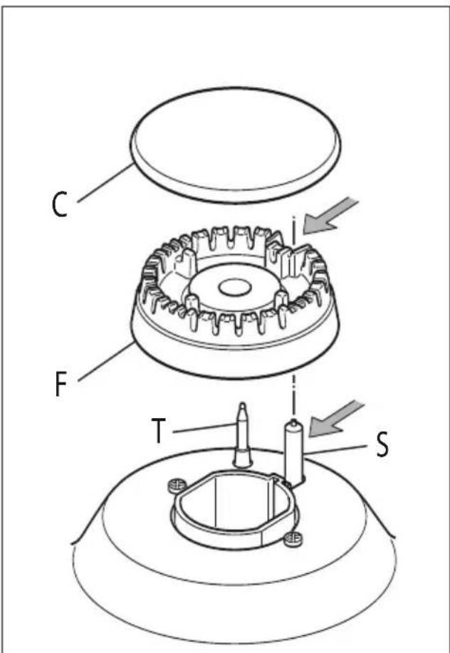
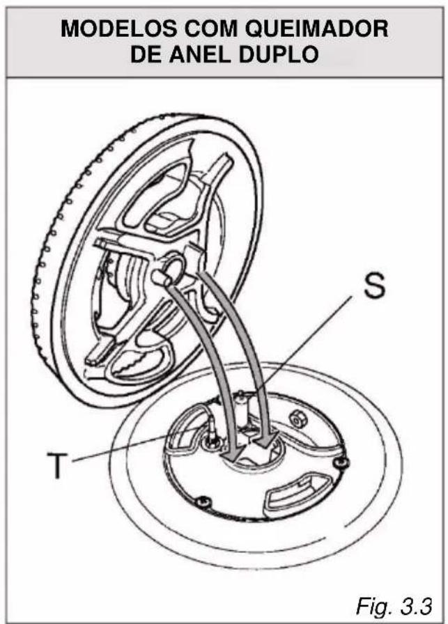
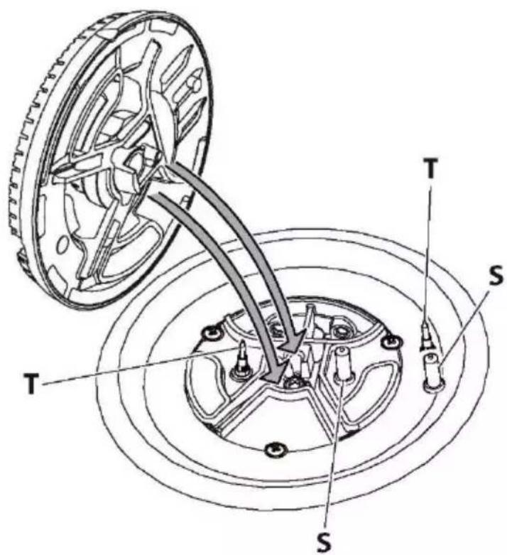
Check that the electrode/s "S" (figs. 3.1, 3.3, 3.4) next to each burner is/are always clean to ensure trouble-free sparking.
Check that the probe/s "T" (figs. 3.1, 3.3, 3.4) next to each burner is/are always clean to ensure correct operation of the safety valves.
Both the probe and ignition plug must be very carefully cleaned.
Note: To avoid damage to the electric ignition do not use it when the burners are not in place.
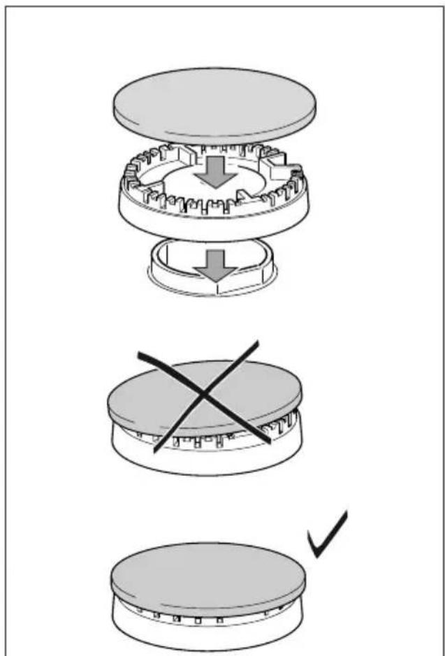
CORRECT REPLACEMENT OF THE AUXILIARY, SEMI-RAPID AND RAPID BURNER
It is very important to check that the burner flame distributor “F” and the cap “C” have been correctly positioned (see figs. 3.1, 3.2) - failure to do so can cause serious problems.
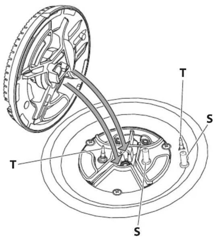
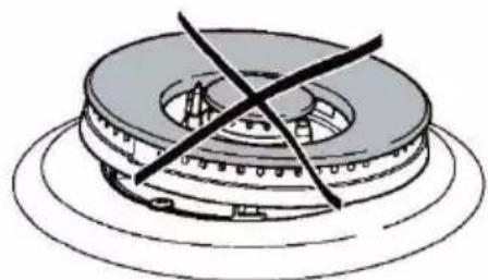
CORRECT REPLACEMENT OF THE DOUBLE-RING AND DUAL BURNER (depending on your model, your cooktop may only have some of these burners - see page 22)
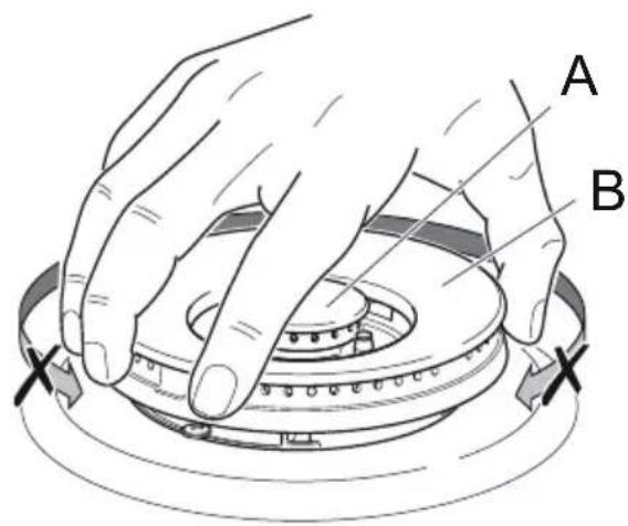
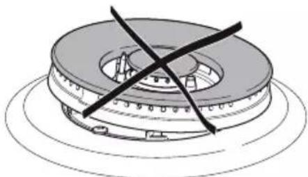
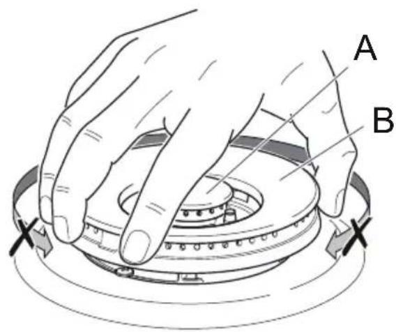
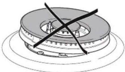
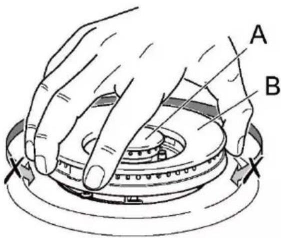
The burner must be correctly positioned; failure to do so can cause serious problems. Fit the flame spreader to the housing as shown by the arrows (see figs. 3.3, 3.4). The burner correctly positioned must not rotate (fig. 3.5).
Then position the cap “A” and the ring “B” (figs. 3.5, 3.6).
text_image
C F T SFig. 3.1 Fig. 3.2
text_image
Diagram illustrating three-step assembly process: top-down, cross-section, and checkmark with arrow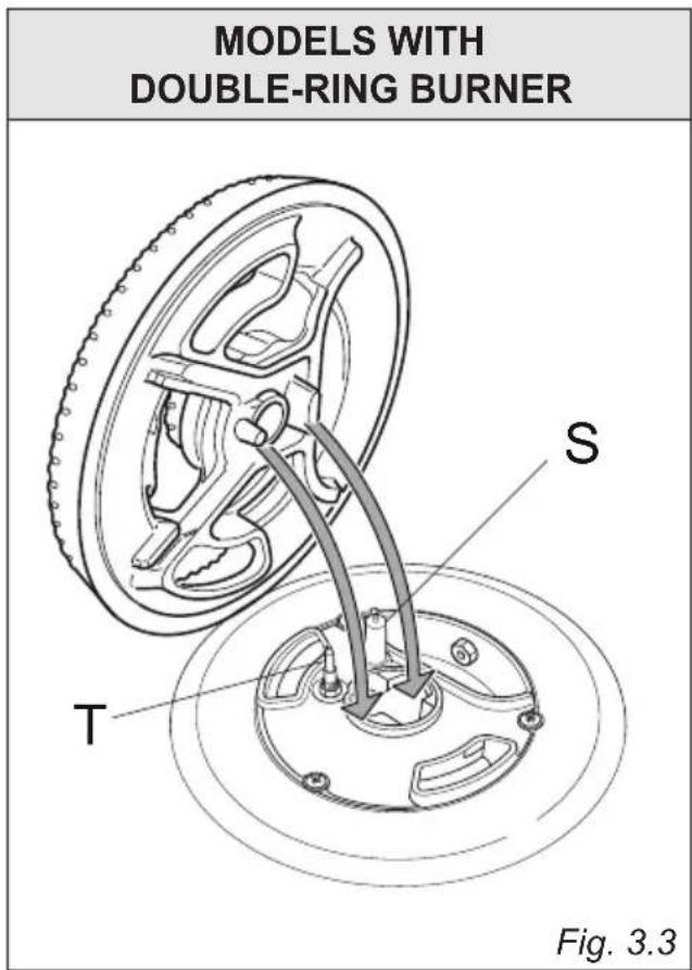
text_image
MODELS WITH DOUBLE-RING BURNER S T Fig. 3.3MODELS WITH
DUAL BURNER

text_image
Technical diagram of a mechanical assembly with labeled components T and S, showing a rotating wheel and internal gear structure.Fig. 3.4
text_image
A BFig. 3.5 Fig. 3.6
natural_image
Diagram of a mechanical component with a central ring and intersecting black lines (no text or symbols)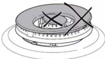
natural_image
Technical illustration of a mechanical component with cross marks, no visible text or symbols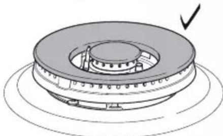
natural_image
Technical illustration of a mechanical component with concentric rings and a checkmark indicating a detail (no text or symbols present)PAN SUPPORTS
These parts can be removed and cleaned with appropriate products.
After cleaning, they must be well dried and correctly replaced.
Warning! Not dishwasher safe.
It is very important to check that the pan supports have been correctly positioned. Failure to do so can cause serious problems.
The prongs of the pan supports must always be centred with the burners (fig. 3.7).
Note: Continuous use may cause a change in the glaze around the burners and grids, corresponding to the areas exposed to the heat. This is a natural phenomenon and does not prevent the parts from working properly.
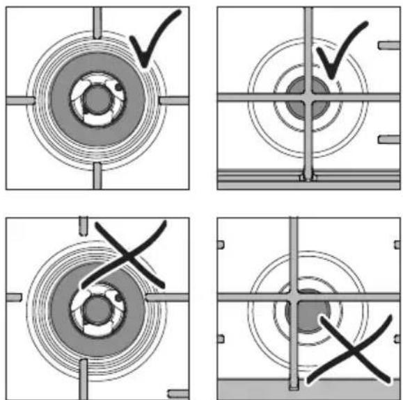
Fig. 3.7
Gentile Cliente
natural_image
Symbol of a trash bin crossed out by two diagonal lines (no text or labels)
AVVERTENZE E CONSIGLI IMPORTANTI PER LA SICUREZZA
MANUTENZIONE PARTE GAS
natural_image
Technical line drawing of a mechanical assembly with labeled component 'F', no readable text or symbols beyond label and figure label (Fig. 3.2)
text_image
L₁ E N (L₂) Fig. 3.3natural_image
Diagram of a circular object with flame-like motion arrows and a starburst symbol, labeled Fig. 2.1a (no text or symbols on the object itself)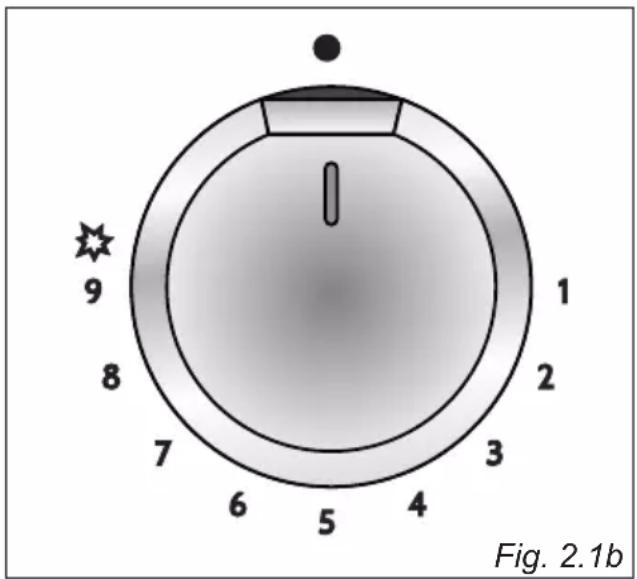
text_image
9 8 7 6 5 4 3 2 1 1 Fig. 2.1bACCENSIONE DEI BRUCIATORI
natural_image
Illustration of a mechanical knob with directional arrows indicating motion (no text or symbols)Fig. 2.2a Fig. 2.2b
text_image
Diagram of a rotary knob with numbered dial and directional arrow, showing motion and rotation patterns.SCELTA DEL BRUCIATORE
natural_image
Prohibition sign showing a crossed-out arrow over leaves, enclosed in a circle (no text or symbols)text_image
Diagram illustrating three-step assembly process: top-down, cross-section, and checkmark with arrow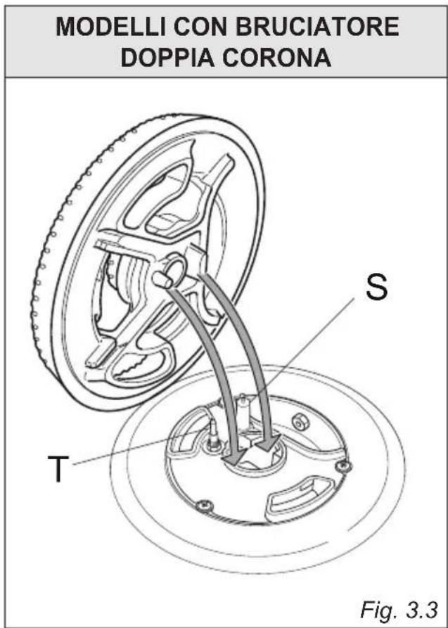
text_image
MODELLI CON BRUCIATORE DOPPIA CORONA S T Fig. 3.3MODELLI CON BRUCIATORE
DUAL

text_image
Technical diagram of a mechanical assembly with labeled components T and S, showing a gear-like component and concentric rings.Fig. 3.4

text_image
A BFig. 3.5 Fig. 3.6

natural_image
Diagram of a mechanical component with a central ring and intersecting black lines (no text or symbols)
natural_image
Technical line drawing of a mechanical component with cross marks, no text or symbols present
natural_image
Technical illustration of a mechanical component with concentric rings and a checkmark indicating a detail (no text or symbols present)GRIGLIE
- Prescriptions de la Directive 93/68/CEE;
- Prescriptions de la Directive 2011/65/UE.

AVERTISSEMENTS POUR L'ÉLIMINATION CORRECTE DU PRODUIT AUX TERMES
DE LA DIRECTIVE EUROPÉENNE 2012/19/UE
natural_image
Symbol of a trash bin crossed with no text or numbers, representing waste sorting or disposal (no text present)
PRECAUTIONS DE SECURITE ET CONSEILS IMPORTANTS
EVACUATION DES PRODUITS DE COMBUSTION
To replace the injectors proceed as follows:
natural_image
Diagram of a cable or pipeline system with labeled component A, showing connections and structural elements (no readable text or symbols)
text_image
FFig. 3.2 Fig. 3.3
text_image
L₁ E N (L₂)natural_image
Diagram of a circular device with flame and smoke, labeled Fig. 2.1a (no text or symbols on the diagram itself)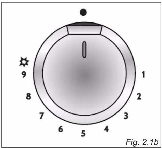
text_image
9 8 7 6 5 4 3 2 1 1 Fig. 2.1bnatural_image
Illustration of a mechanical knob with directional arrows and a star symbol, labeled Fig. 2.2a (no text or symbols on the knob itself)BRÛLEUR DOUBLE - CERTAINS MODELES UNIQUEMENT
GRILLE SPECIALE POUR MARMITES "WOK" (EN OPTION)
(figs. 2.4a - 2.4b)
text_image
INEXACT Fig. 2.4bCONSEILS GENERAUX
natural_image
Prohibition sign with crossed diagonal lines and leafy ground, no text or symbols presentATTENTION
text_image
Diagram illustrating three-step assembly process: top-down, cross-section, and checkmark with arrow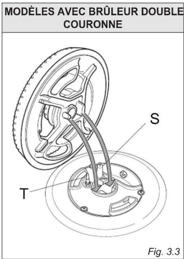
text_image
MODELÈS AVEC BRÛLEUR DOUBLE COURONNE S T Fig. 3.3MODÈLES AVEC BRÛLEUR DOUBLE
text_image
Technical diagram of a mechanical assembly with labeled components T and S, showing a gear-like component and concentric rings.Fig. 3.4
text_image
A BFig. 3.5 Fig. 3.6
natural_image
Mechanical component with cross-shaped clamping mechanism (no text or symbols)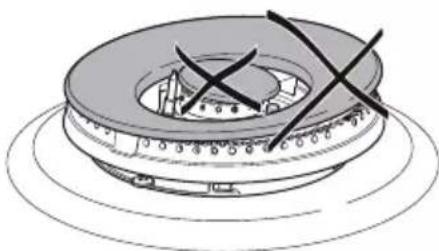
natural_image
Diagram of a mechanical component with cross marks and concentric rings (no text or symbols)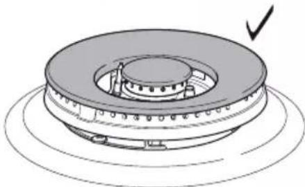
natural_image
Technical illustration of a mechanical component with concentric rings and a curved arrow indicating direction (no text or symbols)natural_image
Circular diagram with concentric rings and a checkmark inside, no text or symbols present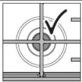
natural_image
Pure mechanical cross-section diagram without any text, numbers, or symbols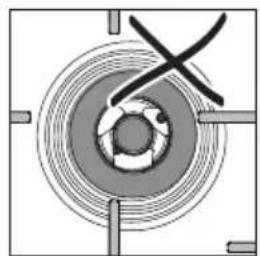
natural_image
Pure mechanical diagram showing concentric circular components with no text or symbols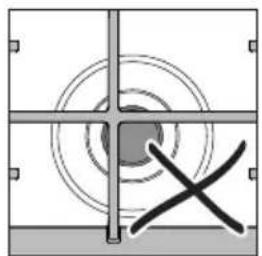
natural_image
Pure geometric diagram with concentric circles and crosshairs, no text or symbols presentFig. 3.7
Caro Cliente,
natural_image
Symbol of a trash bin crossed with two crossed lines and a horizontal bar below (no text or numbers present)PRECAUÇÕES E RECOMENDAÇÕES DE SEGURANÇA IMPORTANTES
natural_image
Technical line drawing of an electrical connector with labeled component 'F' and part number 'Fig. 3.2' (no text or symbols beyond label)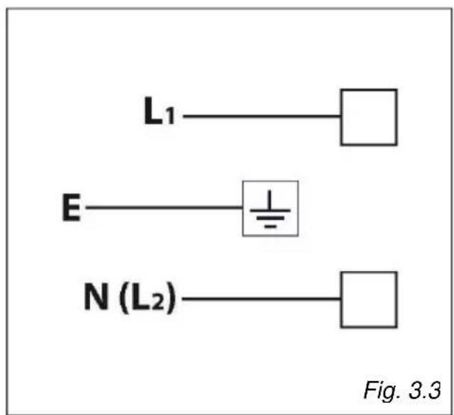
text_image
L₁ E N (L₂) Fig. 3.3UTILIZADORES DO CONSELHO
Fig. 1.1
text_image
5 2 3 1 4 11 7 8 9 10Fig. 1.2
text_image
6 2 3 1 4 13 12 7 8 9 10NOTA:
natural_image
Diagram of a circular device with flame and smoke, labeled Fig. 2.1a (no text or symbols on the diagram itself)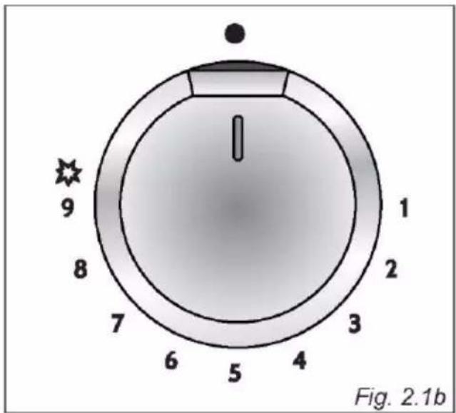
text_image
9 8 7 6 5 4 3 2 1 1 Fig. 2.1bnatural_image
Diagram of a mechanical knob with directional arrows indicating rotation and movement (no text or symbols)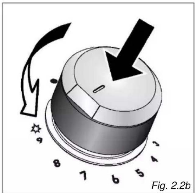
natural_image
Diagram of a mechanical knob with numbered parts and directional arrows indicating motion (no text or symbols)ESCOLHA DO QUEIMADOR
natural_image
Prohibition sign showing a crossed-out fence with a diagonal line, no text or symbols present.text_image
Diagram illustrating three-step assembly process: top-down, cross-section, and final step with checkmark.Fig. 3.2
text_image
MODELOS COM QUEIMADOR DE ANEL DUPLO S T Fig. 3.3MODELOS COM QUEIMADOR DUPLO
text_image
Technical diagram of a mechanical assembly with labeled components T and S, showing a rotating wheel and gear mechanism.Fig. 3.4
text_image
A B XFig. 3.5
natural_image
Diagram of a mechanical component with intersecting lines indicating alignment or dislocation (no text or symbols present)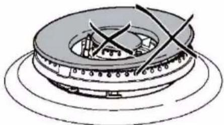
natural_image
Technical line drawing of a mechanical component with no visible text or symbols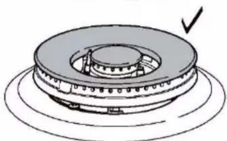
natural_image
Technical illustration of a mechanical component with concentric rings and a checkmark indicating a detail (no text or symbols present)Fig. 3.6
SUPPORTES DE PANELAS
The manufacturer will not be responsible for any inaccuracy resulting from printing or transcript error contained in this brochure. We reserve the right to carry out modifications to products as required, including the interests of consumption, without prejudice to the characteristics relating to safety or function.