TV 225 - Measuring equipment Testboy - Free user manual and instructions
Find the device manual for free TV 225 Testboy in PDF.
| Product Type | True RMS Digital Multimeter Clamp |
| Brand | Testboy |
| Model | TV 225 |
| Dimensions (L x W x H) | 324 x 178 x 30 mm |
| Power Supply | 3 AAA 1.5 V batteries |
| Overvoltage Category | CAT IV 600 V |
| Protection Rating | IP42 |
| Display | LCD with backlight |
| Measurement Point Lighting | Yes, built-in |
| Auto Detection | Yes (AC/DC, resistance, continuity) |
| DC Voltage Measurement Ranges | 6 V / 60 V / 600 V |
| AC Voltage Measurement Ranges | 6 V / 60 V / 600 V (True RMS, 40-2000 Hz) |
| AC Current Measurement Ranges | 60 A / 600 A / 3000 A (True RMS, 40-1000 Hz) |
| Resistance Measurement Ranges | 6 kΩ / 60 kΩ / 600 kΩ / 6 MΩ |
| Frequency Measurement Range | 40 Hz – 10 kHz |
| Continuity Test | Acoustic signal < 50 Ω |
| HOLD Function | Yes, measured value storage |
| Auto Power Off | After 5 minutes of inactivity |
| Operating Temperature | 0 °C to 40 °C, < 80% RH |
| Max. Operating Altitude | Up to 2000 m |
| Maintenance and Cleaning | Clean with a damp cloth and mild detergent; avoid moisture |
| Standards | IEC/EN 61010-1, 61010-2-032, 61326-1 |
Frequently Asked Questions - TV 225 Testboy
User questions about TV 225 Testboy
0 question about this device. Answer the ones you know or ask your own.
Ask a new question about this device
Download the instructions for your Measuring equipment in PDF format for free! Find your manual TV 225 - Testboy and take your electronic device back in hand. On this page are published all the documents necessary for the use of your device. TV 225 by Testboy.
USER MANUAL TV 225 Testboy
natural_image
Line drawing of a handheld electronic device with two leads and a circular top, no text or symbols present.Testboy® TV 225
Version 1.3
de Testboy® TV 225 3
Bedienungsanleitung
en Testboy® TV 225 15
Operating Instructions
fr Testboy ^® TV 225 27
8 HOLD Taste (Speicher)
natural_image
Diagram of a handheld device with a circular component and a diagonal line above it (no text or symbols)text_image
Diagram showing concentric circles with labeled points A, B, C and directional arrows, likely illustrating a physics or engineering concept.General safety notes 16
Description 20
Operation 20
Use 20
Switching on/off 21
Automatic switch-off 21
Display backlight 21
Lighting of the measurement location 21
Reading memory (HOLD) 21
Voltage/resistance/continuity testing 21
AC testing 22
Position fault 22
Definition of the measurement categories 23
Replacing the battery 23
Maintenance 23
Cleaning 24
Test ranges 24
Technical data 26
Testboy ^® TV 225 15
Information
Safety information

WARNING
Sources of danger are, for example, mechanical parts, which may cause serious personal injury.
Objects are also at risk (e.g. damage to the instrument).
WARNING
An electric shock can result in death or serious personal injury, and also functional damage to objects (e.g. damage to the instrument).
WARNING
Never point the laser beam towards the eyes directly or indirectly via reflective surfaces. Laser radiation can cause irreparable damage to the eyes. The laser beam must be deactivated when testing close to people.
General safety notes

WARNING
Unauthorised modification and/or changes to the instrument are not permitted, for reasons of safety and approval (CE). In order to ensure safe and reliable operation using the instrument, you must always observe the safety instructions, warnings and the information contained in the section "Intended use".

WARNING
Please observe the following information before using the instrument:
Do not operate the instrument anywhere near electric welders, induction heaters or other electromagnetic fields.
After abrupt temperature fluctuations, the instrument must be allowed to adjust to the new ambient temperature for approx. 30 minutes before using it, in order to stabilise the IR sensor.
Do not expose the instrument to high temperatures for a long period of time.
Avoid dusty and humid environments.
Measuring instruments and their accessories are not toys, and must be kept out of the reach of children!
In industrial facilities, the accident prevention regulations for electrical systems and equipment, established by the employer's liability insurance association, must be observed.

Please observe the five safety rules:
1 Disconnect
2 Ensure that the instrument cannot be switched back on again
3 Ensure isolation from the power supply (check that there is no voltage on both poles)
4 Earth and short-circuit
5 Cover adjacent live parts
Intended use
The instrument is intended strictly for use in applications described in the operating instructions. Any other usage is forbidden, and may result in accidents or irreparable damage to the instrument. Any such usage will result in the immediate expiry of all guarantee and warranty claims on the part of the operator against the manufacturer.

Remove the batteries if the instrument is not in use for a long period of time, in order to protect the instrument from damage.

We assume no liability for damage to property or personal injury caused by improper handling or failure to observe the safety information. Any warranty claim expires in such cases. An exclamation mark in a triangle indicates safety information in the operating instructions. Read the instructions through before beginning initial commissioning. This instrument is CE-approved and thus fulfils the required guidelines.
We reserve the right to change specifications without prior notice
© 2016 Testboy GmbH, Germany.
Disclaimer

The warranty claim expires in cases of damage caused by failure to observe the instructions! We assume no liability for any resulting damage!
Testboy is not responsible for damage resulting from
failure to observe the instructions
changes to the product that have not been approved by Testboy or
the use of spare parts that have not been manufactured or approved by Testboy
the use of alcohol, drugs or medication.
Accuracy of the operating instructions
These operating instructions have been compiled with due care and attention. No guarantee is given that the data, illustrations and drawings are complete or correct. All rights reserved with regard to changes, printing mistakes and errors.
Disposal
Dear Testboy customer: purchasing our product gives you the option of returning the instrument to suitable collection points for waste electrical equipment at the end of its lifespan.
The WEEE directive regulates the return and recycling of electrical appliances. Manufacturers of electrical appliances are obliged to take back and recycle all electrical appliances free of charge. Electrical devices may then no longer be disposed of through conventional waste disposal channels. Electrical appliances must be recycled and disposed of separately. All equipment subject to this directive is marked with this logo.
Disposal of used batteries
As an end user, you are legally obliged (battery law) to return all used batteries; disposal with normal domestic waste is prohibited!
Batteries containing contaminant material are labelled with this symbol indicating that they cannot be disposed of in normal domestic waste.
The abbreviations used for the respective heavy metals are:
Cd = cadmium, Hg = mercury, Pb = lead.
You can return your used batteries free of charge to collection points in
your community or anywhere where batteries are sold!
Certificate of quality
All activities and processes carried out within Testboy GmbH relating to quality are subject to ongoing monitoring within the framework of a Quality Management System. Furthermore, Testboy GmbH confirms that the testing equipment and instruments used during the calibration process are subject to an ongoing inspection process.
Declaration of conformity
The product conforms to the most recent directives. For more information, go to www.testboy.de
Description
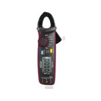
The TV225 digital flexible clamp multimeter can be used to test DC and AC voltage, alternating current, frequency, resistance and continuity.
The electrical parameter to be measured is detected automatically so there is no need for the user to carry out any settings.
text_image
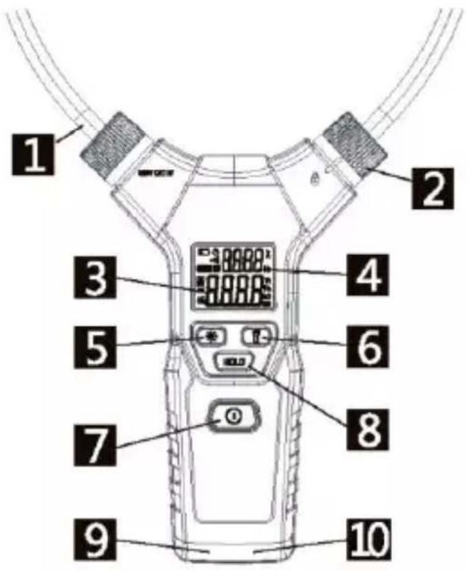
1 2 3 4 5 6 7 8 9 101 Flexible test loop ("clamp")
2 Test loop locking mechanism
3 Main display
4 Auxiliary display
5 Illuminates the display
6 Lights up the measurement location
7 ON/OFF button
8 HOLD button (memory)
9 Measurement socket COM (reference point)
10 Measurement socket V, Ω, o)))
Operation
Use
This multimeter is extremely easy to operate: the electrical parameter to be tested and the correct test range are selected automatically without the user having to select specific functions.
The measured value is then shown on the LC display.
Switching on/off
Switching on: press and hold down the ON/OFF button [7] until you hear a beep.
Switching off: press the ON/OFF button [7]. You will hear a short beep and the display will go off.
Automatic switch-off
When there is no signal to be measured and if no buttons are pressed, the instrument will switch off automatically after five minutes.
Display backlight
Press the button with the sun symbol [5] to switch on the display backlight. Press the button again to switch the backlight off.
Lighting of the measurement location
Press the button with the torch symbol [6] to light up the measurement location. Press the button again to switch off measurement location lighting.
Reading memory (HOLD)
To save the reading (e.g. if it is difficult to see the display at the measurement location), press the HOLD button [8]. The symbol "H" appears on the display. The reading is retained until you press the button again.
Voltage/resistance/continuity testing
Connect the red test lead to the "V, Ω, o)))" socket [10] and the black test lead to the "COM" socket [9].
Use the measurement probes to carry out testing parallel to the voltage source or the resistance. The instrument automatically detects whether DC or AC voltage is present, or switches to resistance testing.
If the resistance values are lower than 50 (continuity), you will hear a continuous beep. The reading appears on the main display.
Where DC voltage is detected, "DC" is displayed. The polarity of the measured voltage in relation to the reference point (black test lead) is also displayed. Negative polarity is indicated by "-".
Where AC voltage is present, "AC" is displayed, and the frequency of the AC voltage is shown in the auxiliary display.
The order of automatic detection is as follows:
AC voltage → DC voltage → AC, resistance/continuity
Operation
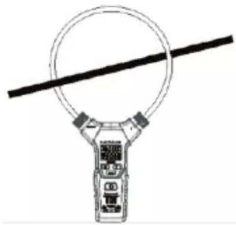
AC testing
Release the test loop locking mechanism, guide the flexible test loop around the conductor to be tested and close the test loop again (see figure). Ensure that the test loop is correctly secured. The mark on the locking mechanism lines up with the " 🔒 " symbol.
Automatic detection switches the instrument to the relevant AC test range.
The reading appears on the main display, and the frequency appears on the auxiliary display
natural_image
Top-down line drawing of a car with a circular head and diagonal line, no text or symbols presentWhen simultaneously measuring the voltage (via the test leads) and current (via the test loop), the main display shows the voltage value and the auxiliary display shows the current instead of the frequency.
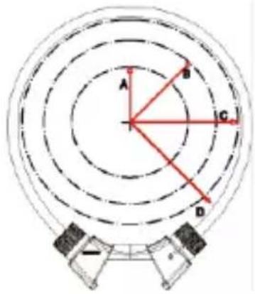
Position fault
The accuracy of the current reading greatly depends on the position of the conductor in the test loop.
Please also note that electrical and magnetic fields affect the test result, and the measurement location should be as free from interferences as possible.
text_image
A B C D| Optimum test radius | Position fault | |
| A | 35 mm | ± 0.5 % |
| B | 50 mm | ± 1.5 % |
| C | 60 mm | ± 2.0 % |
22 Testboy
^® TV 225
| D | >60 mm | ± 5.0 % |
Definition of the measurement categories
Measurement category II: Measurements on circuits directly connected to low voltage networks electrically via plug. Typical short-circuit current < 10 kA
Measurement category III: Measurements within the building installation (stationary consumer devices with non-plug-in connection, distributor connection, permanently installed equipment in the distributor).
Typical short-circuit current < 50 kA
Measurement category IV: Measurements at the source of the low voltage installation (meters, mains connection, primary overcurrent protection). Typical short-circuit current >> 50 kA
To establish the measurement category in a combination of test lead and measuring instrument, the lowest category, of either the test lead or the measuring instrument, always applies.
Replacing the battery
If the battery symbol is displayed, the batteries are dead and need to be replaced.
To do this, switch off the instrument and remove any test leads.
To open the battery compartment on the back of the instrument, undo the holding screw using a Phillips screwdriver size 1. Remove the cover and replace the old batteries with new ones. 3 AAA (Micro) 1.5 V batteries are required.

Batteries must not be disposed of with normal domestic waste. There will be a collection point near you!
Maintenance
The instrument does not require special maintenance when used as specified in these operating instructions.
Cleaning
Use a damp cloth and mild household detergent to clean the instrument should it become soiled through daily use.
Never use aggressive cleaning agents or solvents to clean the instrument.

To prevent electric shocks, do not allow moisture to ingress the housing.
Test ranges
| Range | Resolution | Accuracy | Comment |
| DC voltage | ±0.8% + 3 digits | Min. 0.2 VInput impedance2 MΩMax. 600 Veffective | |
| 6 V | 0.001 V | ||
| 60 V | 0.01 V | ||
| 600 V | 0.1 V | ||
| AC voltage | ±1.2% + 3 digits | ||
| 6 V | 0.001 V | ||
| 60 V | 0.01 V | ||
| 600 V | 0.1 V | ||
| Alternating current | 40 – 65 Hz | Min. 0.15 AMax. 3000 Aeffective40 – 1000 Hz | |
| 60 A | 0.01 A | ±2.0% + 5 digits | |
| 600 A | 0.1 A | ||
| 3000 A | 1 A | ||
| 65 – 1000 Hz | |||
| 60 A | 0.01 A | ±3.0% + 5 digits | |
| 600 A | 0.1 A | ||
| 3000 A | 1 A | ||
| Frequency | ±0.5% + 2 digits | Sensitivity:3 A 40 Hz – 1 kHz | |
| 40 Hz – 1000 Hz | 0.1 Hz |
Test ranges
| 1 kH – 10 kHz | 1 Hz | 0.5 V 40 Hz – 10 kHz | |
| Resistance | ± 1.0 % + 3 digits | Max. 600 V effective | |
| 6 kΩ | 0.001 kΩ | ||
| 60 kΩ | 0.01 kΩ | ||
| 600 kΩ | 0.1 kΩ | ||
| 6 MΩ | 0.001 MΩ |
Technical data
| Test procedure | True RMS |
| Accuracy | |
| DC voltage | ± 0.8 % + 3 digits, min. 0.2 VInput impedance 2 MΩ |
| AC voltage | ± 1.2 % + 3 digits, min. 0.5 V at 45 – 65 Hz± 2.0 % + 5 digits, min. 0.5 V at 65 – 2000 HzInput impedance 2 MΩ |
| Alternating current | ± 3.0 % + 5 digits |
| Frequency | ± 0.5 % + 2 digits |
| Resistance | ± 1.0 % + 3 digits |
| Continuity | Beep < 50 Ω, test current 1 mA |
| Scan frequency | 3 Hz |
| Operating conditions | 0 – 40 °C at < 80 % RH< 2000 m above MSL |
| Dimensions LxWxH | 324 x 178 x 30 mm |
| Protection class | IP 42 |
| Overvoltage category | CAT IV 600 V |
| Testing standard | IEC/EN 61010-1, 61010-2-032, 61326-1 |
| Voltage supply | 3x 1.5 V type AAA Micro |
Table des matières
Consignes 28
Cd = Cadmium, Hg = mercure, Pb = plomb.
natural_image
Top-down line drawing of a car with a circular head and diagonal line, no text or symbols presenttext_image
Diagram showing concentric circles with labeled points A, B, C, D and directional arrows, likely illustrating a physics or engineering concept.natural_image
Top-down line drawing of a car with a circular head and diagonal line, no text or symbols presentnatural_image
Simple line drawing of a handheld device with a circular ring and a horizontal line (no text or symbols)Cd = cadmium, Hg = kwikzilver, Pb = lood.