KDE3-24 - Boiler KOSPEL - Free user manual and instructions
Find the device manual for free KDE3-24 KOSPEL in PDF.

| Product type | Instantaneous electric water heater |
| Brand | Kospel |
| Model | KDE3-24 |
| Power supply | 400 V ~ 3 phases |
| Rated power | 24 kW (adjustable from 9 to 27 kW depending on configuration) |
| Rated current | 34.6 A |
| Dimensions (H x W x D) | 440 x 245 x 126 mm |
| Weight | Approximately 4.85 kg |
| Water supply pressure | 0.1 – 1.0 MPa |
| Minimum activation flow rate | 2.5 L/min |
| Temperature range (Normal mode) | 30 – 60 °C |
| Temperature range (Shower mode) | 30 – 55 °C |
| Hydraulic connection | G 1/2" (pipe spacing) |
| Minimum power cable cross-section | 4 x 2.5 mm² |
| Maximum power cable cross-section | 4 x 16 mm² |
| Protection indices | 30 mA residual-current circuit breaker recommended |
| Main functions | Instantaneous water heating, LCD display, temperature adjustment, presets (ECO, SINK, BATH), flow detection, overheat protection, air detection, NO blocking input, BLOK relay output |
| Maintenance and cleaning | Periodic cleaning of strainer, regular descaling (frequency depending on water hardness) |
| Safety | Safety switch, overvoltage protection, mandatory residual-current circuit breaker, automatic shutdown in case of error (overheat, air) |
| Repairability | Authorized after-sales service (KOSPEL Repair Hotline: 0241 910504 50) |
| General information | Indoor use only, wall mounting on flat surface, do not expose to frost, do not use plastic pipes |
Frequently Asked Questions - KDE3-24 KOSPEL
User questions about KDE3-24 KOSPEL
0 question about this device. Answer the ones you know or ask your own.
Ask a new question about this device
Download the instructions for your Boiler in PDF format for free! Find your manual KDE3-24 - KOSPEL and take your electronic device back in hand. On this page are published all the documents necessary for the use of your device. KDE3-24 by KOSPEL.
USER MANUAL KDE3-24 KOSPEL
This appliance can be used by children aged from 3 years and above and persons with reduced physical, sensory or mental capabilities or lack of experience and knowledge if they have been given supervision or instruction concerning use of the appliance in a safe way and understand the hazards involved. Children shall not play with the appliance. Cleaning and user maintenance shall not be made by children without supervision.
- Read and strictly follow the installation and operating instructions to ensure a long life and reliable unit operation.
- The unit is designed to be mounted only on the flat wall.
- The water heater is designed to heat DHW in households, sanitary facilities, laboratories and workshops etc.
- The unit can only be used when in perfect technical condition and correctly assembled.
- If there is a non-return valve installed on the water supply pipe the safety valve must be fitted between unit and non-return valve.
- Inlet and outlet pipes should not be made of plastic.
- The maximum inlet water temperature should not exceed 60^ .
- The unit should always be vented before initial start-up. Vent the unit each time after the water has been emptied from the heater or pipes (e.g. when water supply system has been repaired or maintained).
- Connection to the mains and measurement of fire protection effectiveness should be made by a qualified person.
- Water heater must be unconditionally connected to protective grounding- the quality of which (continuity of the protective conductor) should be checked periodically by qualified electrician. It is recommended to install heater on grounded, steel or copper hydraulic fittings.
- According to the general norms, electrical installation must be equipped with current differential switch of high sensitivity (of max rated current 30mA ), whereby we recommend installing a separate four-pole residual current circuit breaker (regardless of the remaining part of the installation) of current 10 or 30mA .
- Electric installation should be equipped with residual current protective devices and other solutions which will ensure disconnecting the heater from the source of power (intervals between all their poles should not be less than 3mm ).
-
The unit must not be installed in the place which is exposed to the danger of explosion and place in which the temperature may go down below 0^ .
-
Storage of water heater in the rooms where temperature drops below 0 degrees may result in its damage (there is water inside the device) and may eventually lead to the loss of warranty rights.
- Do not use when the water has been emptied from the unit or pipes (e.g. when water supply system has been repaired or maintained).
- Unit's cover must not be taken off while power is on.
- Failure to install the filter on water supply pipe can cause unit damage.
- Lime scale built-up on heater's elements may limit water flow and lead to heater's damage. Such damages are not subjected to warranty rights. Water heater and sanitary fittings should be periodically descaled, whereas, frequency this process should be adjusted to water hardness in given installation. Lime scale built-up may be partially limited by usage of magnetic descalers installed on the cold water inlet pipe.
- Appropriate precaution must be taken when using hot water. Temperature of water over 40^ may cause hot feeling and can be dangerous for children, whereas, temperature above 50^ may lead to first degree burn (especially amongst small children).
- Electronically controlled heater is a electrical surge sensitive device, therefore the electrical installation must contain surge protection devices.
- Water heater should be mounted in such a way in order to enbale easy access for service and service repair. It is connected with keeping minimal distance from the walls and the ceiling of min. 100mm
- Apply template on place the unit will be fitted. Mark points for drilling the holes for fixing screws.
- Bring the water system pipes and electric supply cables to the marked places.
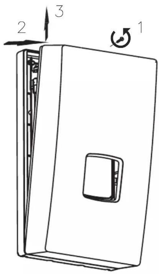
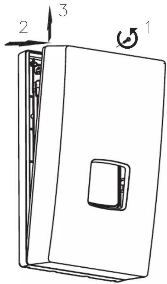
- Take off the unit's cover.
- Install the heater on fixing screws after running the supply wire through the hole and fix the unit.
- Connect the unit to the electric mains.
- Remove rubber plugs from cold and hot water fittings.
- Connect the unit to the water supply system.
- Open the cold water valve and check for leaks.
- Vent the water system. See section "Venting".
- During heater's installation, check the activation of safety switch (only applies to the first connection of the device).
- Put the unit's cover back.
- Make sure that there is no access to live parts through the holes at the back plate.
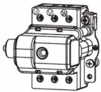
Safety switch
a) - to switch on
b) - safety switch on
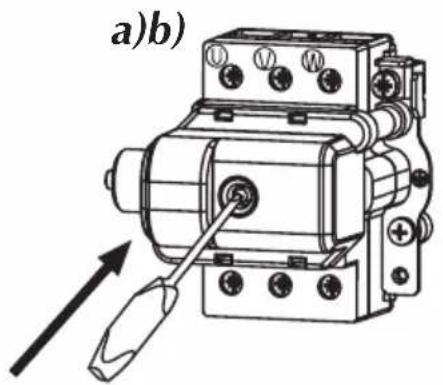
Attention! In the event of a safety switch being triggered during operation, please contact the service.
Switching on the safety switch again and continuing to use the device may cause danger and serious damage to the heater.
- Shut off electric supplies to the heater.
- Turn the flow on (turn the hot water tap on) in order to vent the water installation (for about 15-30 seconds), until the flow of water becomes constant and even.
- Switch on the electric supplies.
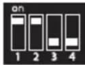
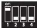
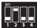
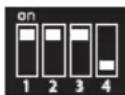
Configuration
Heating box size 15kW

9 kW

11 kW

12 kW

15 kW
Heating box size 24kW

17 kW
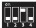

18 kW
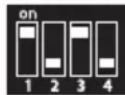

21 kW
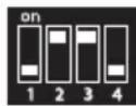

24 kW
Heating box size 27kW
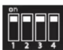

27 kW
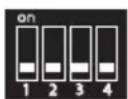
White square shows the switch position.
Notice! Configuration must be performed before initial start-up when power supply is switched off. Set 2 (two) switches at proper position to configure a heater. The switches are located on electronic board. Each switch has 4 (four) positions, they are described as (power settings) and (other settings). Switch on a power supply to upgrade configuration. After you supply power to KDE5 a display will show: (PW...) - software version of control panel, (MSP...) - software version of controller and the value of rated power that has been set for the heater.
switches settings: P
- 1,2 - rated power of heater,
3, 4 - type of heating box,
switches settings F:
- 1, 2, 3 - do not change! keep factory settings,
- 4 - ON - blocks access to the heater's settings.
In this case in KDE 5, the display shows the desired temperature value (which has been adjusted before the heater is off), the heating icon and other possible working characteristics.
The heater is factory set at NORMAL mode (30 - 60^) . To use the heater for shower purposes it has to be changed to SHOWER mode (30 - 55^) . Change of the modes can only be done by authorised service.
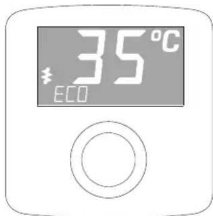
The heater switches on automatically straight after reaching the flow rate over 2,5 l/min. The temperature control system adjusts the power rate according to the water flow rate, required temperature and the temperature of water in the mains. The LCD backlight and icon signalises the heating operation. If the unit reach the maximum power value which is too low for a given operating conditions the LCD display will show flickering icon . The LED display backlight also turns on while pushing or turning the setting knob. The backlight will automatically turn off when the
heating operation is turned off, or if more than 50 seconds have passed since the last adjustment.
If you block the unit by master appliance (NA entry) the display will show "EXT BLOCKED". If the fault occurs the display will show Econ and error message.
Error messages:
- ER>T INLET - inlet sensor failure,
- ER> T MAX - temperature has exceeded the maximum value,
- ER> AIR 1 - air bubbles in the heating box - equipment detection,
ER> AIR 2 - air bubbles in the heating box - program detection.
If the display shows ER> T MAX, ER> AIR 1 or ER> AIR 2 the unit will stop heating. The unit will not heat again until the failure is resolved and the appropriate value of water flow is reached.
Temperature adjustment
The current temperature is displayed on LCD. Turn the knob to the right to increase the temperature value, or to the left to decrease it.
Push the knob to read the temperature value that is stored in memory. Push it again to read the next stored value. You can switch between the following settings: „ECO“ „SINK“ and „BATH“.
To change the temperature setting in memory:
- select the temperature setting by pushing the control knob,
- push the knob and keep for about 3 seconds until the value starts to flashing,
- turn the knob to adjust the value,
- push the knob to save the value.
Notice: save the new value within 10 seconds, otherwise you will lose it.
Configuration and parameters view
Set the minimum temperature value then push and keep knob for about 5 seconds until the display shows > SETPOINT". Turn a knob to select the required value. There are some parameters that are not changeable by the user (e.g. INLET, POWER), or can be used to change the work configuration only (e.g. display brightness, language version). To change the parameters value push (position flickering) and turn the knob. Push the knob to confirm a change.
Notice: confirm a new parameter value within 10 seconds, otherwise you will lose it.
The new parameter value will be saved when you exit menu using [EXIT].
You can switch between the following parameters:
- [>T SETPOINT] temperature (min-max) - °C,
- [>T INLET] inlet temperature value - ^ C
- [>T OUTLET] outlet temperature value - °C,
- [>FLOW] flow rate - l/min,
- [>POWER] percentage of maximum power with which the unit currently heats, -%,
- [>T - h] work time,
- [>BRIGH MIN] minimum brightness / stand-by-mode (0 - BRIGH MAX),
- [>BRIGH MAX] maximum brightness / active (BRIGH MIN -25),
- [>ENGLISH] select language version,
- [>TEMP LIMIT] maximum temperature limit (min setting - max setting),
Notice: a new maximum temperature value will be saved in memory for other temperature settings as well,
If you try to set the temperature above the adjusted maximum value the display will show for about 1 second.
- [>TEST] for authorized service only,
- [>POWER SET] configured power value,
- push knob to check a software version (PW...,MSP...),
- restore to factory settings [FACTORY SET] or to restart controllers [RESET],
- push and keep knob (for about 5sec., until the display show [-]) to up grate [FACTORY SET] and [RESET] function,
- [>EXIT] save a new parameter and menu exit.
Notice: parameters view mode will automatically exit (without saving changes) after 5 minutes since the last adjustment.
The heater switches on automatically straight after reaching the flow rate over 2,5l/min. The temperature control system adjusts the power rate according to the water flow rate, required temperature and the water temperature in the mains.
There are two indicators on the case:
-
green - power supply "on",
-
red - heating "on".
Other modes are shown by flickering green light.
| Number of impulses (green indicator) | Description |
| 1 | The unit was switched off because the temperature has exceeded the maximum value (fault signal will not disappear until the appropriate rate of water flow is reached). |
| 2 The unit was switched off by a master appliance | |
| 3 The inlet temperature sensor failure | |
| 4 | The unit was switched off because the air bubbles in the heating box (the unit will not heat again until the fault is resolved and the appropriate rate of flow is reached). |
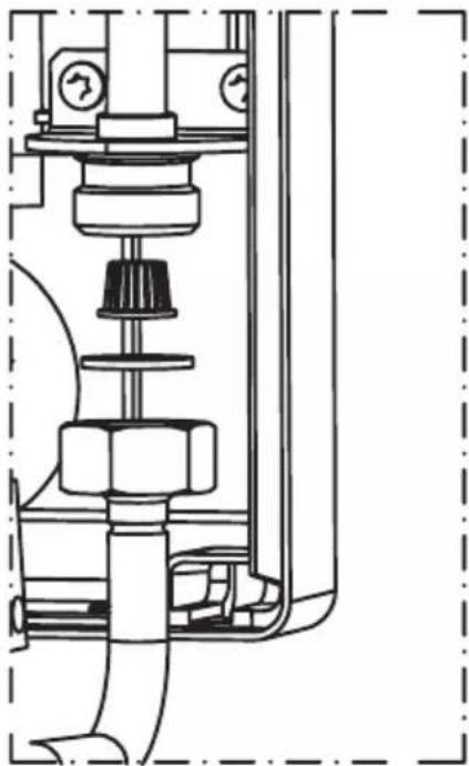
Filter cleaning:
- Cut off power and cold water supplies.
- Take off the unit's cover.
- Undo the inlet fitting - on the cold water side.
- Take the filter out from the inlet fitting.
- Clean up the filter.
- Fix the filter back, put the gasket and do up the inlet fitting.
- Open the cut-off valve on cold water supply pipe check connections for leaks.
- Fix the unit's cover back.
- Vent the water system - see "Venting section".
Co-operation with other appliances
Unit is equipped with the BLOCK and NA clamps.
BLOCK - relay input that switches off the slave appliance, the circuit that is connected to the BLOCK clamps (max. 0,1A 250V-) will be opened at the time of heating operation starts up.
NA - input that locks the unit operation, opened NA contacts locks the heating operation-co-operation with the master appliance.
Wire (2 x 0,5sq mm) for BLOCK and NA clamps showuld be run inside the unit on the right side. The wire connections must be performed by a qualified person.
| Heater KDE3; KDE5 | 9/11/12/15 17/18/21 | 24 27 | ||||||||
| Rated power kW 9 11 12 15 17 18 21 24 | 27 | |||||||||
| Rated voltage 400V 3~ | ||||||||||
| Rated current | A | 3x13,0 | 3x15,9 | 3x17,3 | 3x21,7 | 3x24,7 | 3x26,0 | 3x30,3 | 3x34,6 | 3x39,0 |
| Efficiency (at Δt = 30°C and water pressure at 0,45 MPa) | 1/min | 4,3 5,2 5 | 8 7,2 8, | 1 8,7 10, | 1 11, | 6 13 | ||||
| Min. connecting wires section | mm² | 4 x 2,5 | 4 x 6 | |||||||
| Max. connecting wires section | mm² | 4 x 16 | ||||||||
| The maximum allowed network impedance | Ω | 0,43 | 0,37 | 0,30 | ||||||
| Overall dimension (height x width x depth) | mm | 440 x 245 x 126 | ||||||||
| Weight | kg | ~4,85 | ||||||||
| Pressure in the water mains | MPa | 0,1 ÷ 1,0 | ||||||||
| Activation point (min. rate of flow) | l/min | 2,5 | ||||||||
| Temperature adjustment range | NORMAL mode | 30 ÷ 60 | ||||||||
| SHOWER mode | 30 ÷ 55 | |||||||||
| Water fittings | G 1/2" (distance between inlet and outlet 100 mm) | |||||||||
The minimal resistivity of water at 15^ is 1100 cm
79 ix wina h79 by annn nn
11
ynnn nn (30mA nno n no n) nn nn nn nn
mA 10-30 ynnn 4 nn
"y yon nn nnnn 17 19 nn nn on xN ,yT I Oyn Dn ninn
.0ININ'U7NNND
7nnn nn nnnn nn nnnnnnnnnnnnnnnnnnnnnnnnnnnnnnnnnnnnnnnnnnnnnnnnnnnnnnnnnnnnnnnnnnnnnnnnnnnnnnnnnnnnnnnnnnnnnnnnnnnnnnnnnnnnnnnnnnnnnnnnnnnnnnnnn
nno .nnnn nniin no.1
n
.2
.3
4
.0INnn n90x
.5
.6
7
.177 w9ni a7n nn dinov nx n9 .8
"innn" n 9 nn nn nn nn .9
.
X .D D NNNN NNNN NNNN NNNN NNNN NNNN NNNN
niv nnn nn nnn, nnnn nn npnn nn ny nn noy no
TEST
bwnn - POWER SET.
.ENTNNN NYYYyNNTNNNNTNNN - EXIT
nnnnnnnn (nnw) npt 5 nnovn nnx ny
n 2.5 w nwn ynn nnynnn nn nn nn nn nn nn nn nn nn nn nn nn nn nn nn nn nn nn nn nn nn nn nn nn nn nn nn nn nn nn nn nn nn nn nn nn nn nn nn nn nn nn nn nn nn nn nn nn nn nn nn nn nn nn nn nn nn nn nn nn nn nn nn nn nn nn nn nn nn nn nn nn
777 777777777
"ON" nnn npdox - p77
"ON" 177
777 777 777 777 777 777 777 777
Used product can't be treated as general communal waste. Disassembled appliance has to be delivered to the collection point of electrical and electronic equipment for recycling. Appropriate utilisation of used product prevents potential negative environmental influences that may occur as a result of inappropriate handling of waste. In order to get more detailed information about recycling this product you should contact the local government unit, waste management service or the shop where this product has been purchased.