Ironmeter - Multimeter HT Instruments - Free user manual and instructions
Find the device manual for free Ironmeter HT Instruments in PDF.

| Product type | Digital Multimeter |
| Brand | HT Instruments |
| Model | Ironmeter |
| Category | TRMS Multimeter |
| Dimensions (L x W x H) | 120 x 65 x 45 mm |
| Power Supply | 2 x 1.5V AAA alkaline batteries (LR03) |
| Autonomy | Auto Power OFF after 15 minutes (disablable) |
| Display | LCD 4000 counts, backlight |
| Measurement Functions | AC/DC Voltage, AC/DC Current, Resistance, Continuity, Diodes, Capacitance, Frequency, Duty Cycle |
| Max Voltage | 600 V DC/AC |
| Max Current | 10 A (20 A for 30 s max) |
| Max Resistance | 40.00 MΩ |
| Max Capacitance | 4000 µF |
| Max Frequency | 10 kHz (electronic) |
| Continuity Test | Threshold < 50 Ω with audible tone |
| Diode Test | Test current < 0.35 mA, open circuit voltage 3 V DC |
| Safety | CAT III 600 V, double insulation, pollution degree 2 |
| Standards | IEC/EN61010-1, IEC/EN61326-1 |
| Included Accessories | Pair of test probes, batteries, pouch, user manual |
| Maintenance | Cleaning with dry cloth, battery and fuse replacement |
| Spare Parts | Fuses F10A/600V and F500mA/600V (5x20mm), AAA batteries |
| Warranty | According to general terms and conditions of sale |
Frequently Asked Questions - Ironmeter HT Instruments
User questions about Ironmeter HT Instruments
0 question about this device. Answer the ones you know or ask your own.
Ask a new question about this device
Download the instructions for your Multimeter in PDF format for free! Find your manual Ironmeter - HT Instruments and take your electronic device back in hand. On this page are published all the documents necessary for the use of your device. Ironmeter by HT Instruments.
USER MANUAL Ironmeter HT Instruments
IRONMETER
Manuale d'uso
User manual
natural_image
Abstract black-and-white geometric logo with stylized letter 'E' and lightning bolt-like shapes (no text or symbols)Indice generale General index Índice general Inhalt Table des matières
ITALIANO IT - 1
ENGLISH ...... EN - 1
1. PRECAUTIONS AND SAFETY MEASURES 2
1.1. Preliminary instructions....2
1.2. During use....3
1.3. After use.... 3
1.4. Definition of Measurement (Overvoltage) category 3
2. GENERAL DESCRIPTION 4
3. PREPARATION FOR USE 4
3.1. Initial checks....4
3.2. Instrument power supply 4
3.3. Calibration 4
3.4. Storage....4
4. OPERATING INSTRUCTIONS....5
4.1. Description of the instrument....5
4.1.1. Description of the controls 5
4.2. Description of function keys 6
4.2.1. HOLD/ key 6
4.2.2. MODE/ key 6
4.2.3. RANGE key 6
4.2.4. MAX MIN key 6
4.2.5. Disabling the Auto Power OFF function 6
4.3. Description of rotary switch functions....7
4.3.1. DC Voltage measurement 7
4.3.2. AC Voltage measurement 8
4.3.3. Resistance measurement and Continuity test....9
4.3.4. Diode test.... 10
4.3.5. Capacitance measurement.... 11
4.3.6. DC Current measurement 12
4.3.7. AC Current measurement.... 13
5. MAINTENANCE 14
5.1. Replacing the batteries and the internal fuses 14
5.2. Cleaning the instrument 14
5.3. End of life 14
6. TECHNICAL SPECIFICATIONS ....15
6.1. Technical characteristics.... 15
6.1.1. Reference standards 17
6.1.2. General characteristics.... 17
6.2. Environment 17
6.2.1. Environmental conditions for use 17
6.3. Accessories....17
6.3.1. Accessories provided 17
7. ASSISTANCE....18
7.1. Warranty conditions.... 18
7.2. Assistance....18
1. PRECAUTIONS AND SAFETY MEASURES
The instrument has been designed in compliance with directive IEC/EN61010-1 relevant to electronic measuring instruments. For your safety and in order to prevent damaging the instrument, please carefully follow the procedures described in this manual and read all notes preceded by symbol ▲with the utmost attention.
Before and after carrying out measurements, carefully observe the following instructions:
- Do not carry out any measurement in humid environments.
- Do not carry out any measurements in case gas, explosive materials or flammables are present, or in dusty environments.
- Avoid any contact with the circuit being measured if no measurements are being carried out.
- Avoid any contact with exposed metal parts, with unused measuring probes, circuits, etc.
- Do not carry out any measurement in case you find anomalies in the instrument such as deformation, breaks, substance leaks, absence of display on the screen, etc.
- Pay special attention when measuring voltages higher than 20V, since a risk of electrical shock exists.
In this manual, and on the instrument, the following symbols are used:
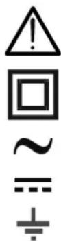
Warning: observe the instructions given in this manual; improper use could damage the instrument or its components.
Double-insulated meter
AC voltage
DC voltage or current
Connection to earth
1.1. PRELIMINARY INSTRUCTIONS
- This instrument has been designed for use in environments of pollution degree 2.
- It can be used for VOLTAGE and CURRENT measurements on installations in CAT III 600V.
- We recommend following the normal safety rules devised by the procedures for carrying out operations on live systems and using the prescribed PPE to protect the user against dangerous currents and the instrument against incorrect use.
- In case the lack of indication of the presence of voltage may represent a danger for the operator, always carry out a continuity measurement before carrying out the measurement on the live system, in order to confirm the correct connection and condition of the leads.
- Only the leads supplied with the instrument guarantee compliance with the safety standards. They must be in good conditions and be replaced with identical models, when necessary.
- Do not test circuits exceeding the specified voltage limits.
- Do not perform any test under environmental conditions exceeding the limits indicated in § 6.2.1.
- Check that the battery is correctly inserted.
- Make sure that the LCD display and the rotary switch indicate the same function.
1.2. DURING USE
Please carefully read the following recommendations and instructions:
CAUTION
Failure to comply with the caution notes and/or instructions may damage the instrument and/or its components or be a source of danger for the operator.
- Before activating the rotary switch, disconnect the test leads from the circuit being measured.
- When the instrument is connected to the circuit being measured, do not touch any unused terminal.
- Do not measure resistance in case external voltages are present; even if the instrument is protected, an excessive voltage may cause malfunction.
- While measuring, if the value or the sign of the quantity being measured remain unchanged, check if the HOLD function is enabled.
1.3. AFTER USE
- When measurement is complete, set the rotary switch to OFF to turn off the instrument.
- If the instrument is not to be used for a long time, remove the batteries.
1.4. DEFINITION OF MEASUREMENT (OVERVOLTAGE) CATEGORY
Standard “IEC/EN61010-1: Safety requirements for electrical equipment for measurement, control and laboratory use, Part 1: General requirements”, defines what measurement category, commonly called overvoltage category, is. § 6.7.4: Measured circuits, reads:
(OMISSIS)
Circuits are divided into the following measurement categories:
- Measurement category IV is for measurements performed at the source of the low-voltage installation.
Examples are electricity meters and measurements on primary overcurrent protection devices and ripple control units.
- Measurement category III is for measurements performed on installations inside buildings.
Examples are measurements on distribution boards, circuit breakers, wiring, including cables, bus-bars, junction boxes, switches, socket-outlets in the fixed installation, and equipment for industrial use and some other equipment, for example, stationary motors with permanent connection to fixed installation.
- Measurement category II is for measurements performed on circuits directly connected to the low-voltage installation.
Examples are measurements on household appliances, portable tools and similar equipment.
- Measurement category I is for measurements performed on circuits not directly connected to MAINS.
Examples are measurements on circuits not derived from MAINS, and specially protected (internal) MAINS-derived circuits. In the latter case, transient stresses are variable; for that reason, the standard requires that the transient withstand capability of the equipment is made known to the user.
2. GENERAL DESCRIPTION
The instrument carries out the following measurements:
- DC voltage
- AC TRMS voltage
- DC current
- AC TRMS current
- Resistance and Continuity test
- Frequency
- Duty Cycle
- Diode test
- Capacity
Each of these functions can be activated by means of the appropriate switch. The instrument is also provided with a HOLD/∅, MODE/∅, RANGE and MAXMIN button. For their use, please refer to § 4.2. The instrument is also equipped with a white light torch and an Auto Power OFF function which automatically switches off the instrument 15 minutes after the last time a function key was pressed or the rotary switch was turned.
3. PREPARATION FOR USE
3.1. INITIAL CHECKS
Before shipping, the instrument has been checked from an electric as well as mechanical point of view. All possible precautions have been taken so that the instrument is delivered undamaged.
However, we recommend generally checking the instrument in order to detect possible damage suffered during transport. In case anomalies are found, immediately contact the forwarding agent.
We also recommend checking that the packaging contains all components indicated in § 6.3.1. In case of discrepancy, please contact the Dealer.
In case the instrument should be returned, please follow the instructions given in § 7.
3.2. INSTRUMENT POWER SUPPLY
The instrument is supplied with 2x1.5V alkaline batteries type IEC AAA LR03, included in the package. When the battery is flat, the symbol “t-appears on the display. To replace the battery, see § 5.1.
3.3. CALIBRATION
The instrument has the technical specifications described in this manual. The instrument's performance is guaranteed for one year.
3.4. STORAGE
In order to guarantee precise measurement, after a long storage time under extreme environmental conditions, wait for the instrument to come back to normal condition (see § 6.2.1).
4. OPERATING INSTRUCTIONS
4.1. DESCRIPTION OF THE INSTRUMENT
4.1.1. Description of the controls
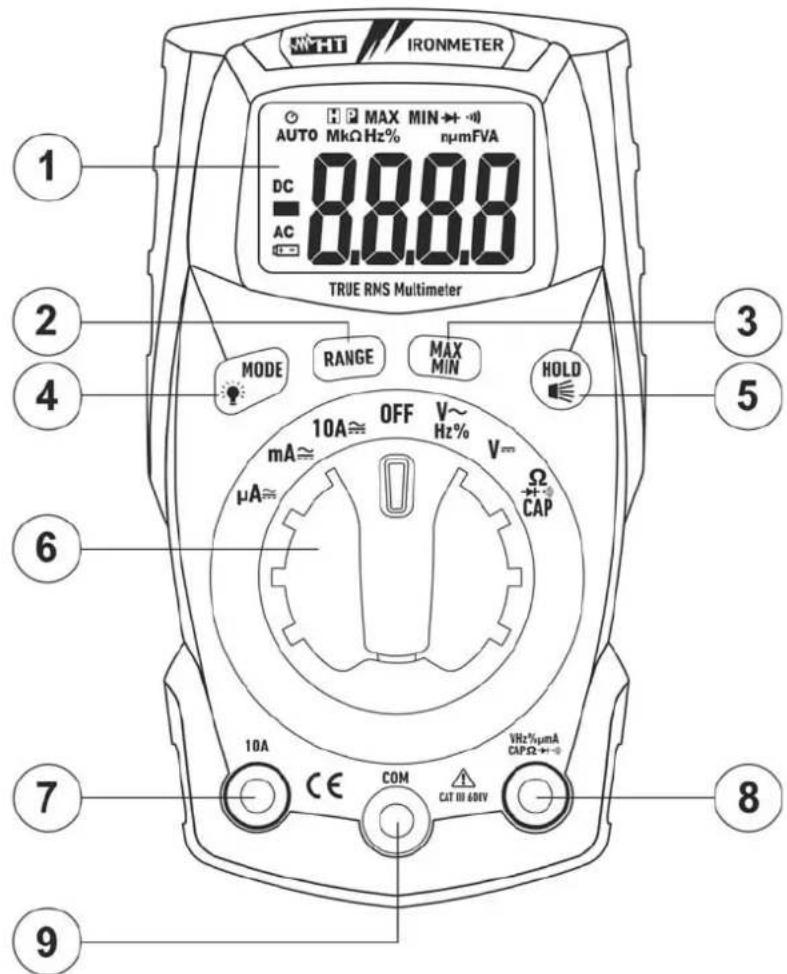
CAPTION:
- LCD display
- RANGE key
- MAXMIN key
- MODE/ key
- HOLD/ key
- Rotary selector switch
- Input terminal 10A
- Input terminal
$$ \mathrm{VHz} \% \mathrm{m} \mu \mathrm{ACAP} \Omega - + \cdot 1)) $$
- Input terminal COM
Fig. 1: Description of the front part of the instrument
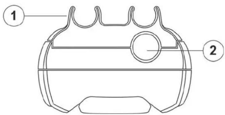
CAPTION:
- Slots for lead connection
- White light
Fig. 2: Description of the upper part of the instrument
4.2. DESCRIPTION OF FUNCTION KEYS
4.2.1. HOLD/ key
Pressing the HOLD/⌘ key freezes the value of the measured quantity on the display. After pressing this key, the message "H" appears on the display. Press the HOLD/⌘ key again to exit the function.
Press and hold the HOLD/ key to activate/deactivate the white light on the upper part of the instrument (see Fig. 2 – part 2).
4.2.2. MODE/ ⚙ key
The MODE/★ key is used in position “Ω▶+”CAP” to select resistance measurement, continuity test, diode test and capacity test, in position “VHz%\~” to select measurement of voltage, frequency and duty cycle, in position “μA≡”, “mA≡” and “10A≡” to select AC or DC measurement.
Long pressing the MODE/☀ key activates/deactivates the display's backlight. This function is active in any position of the rotary switch.
4.2.3. RANGE key
Press the RANGE key to disable the Autorange function. The symbol "AUTO" disappears from the upper left part of the display. In manual mode, press the RANGE key to change measuring range: the relevant decimal point will change its position. The RANGE key is not active in positions Hz%, CAP, ▶ and •) In Autorange mode, the instrument selects the most appropriate ratio for carrying out measurement. If a reading is higher than the maximum measurable value, the indication "O.L" appears on the display.
Long pressing the RANGE key (or upon switching on the instrument again) allows quitting the manual mode and restoring the Autorange mode.
4.2.4. MAX MIN key
Pressing the MAX MIN key once activates the detection of maximum and minimum values of the quantity being tested. Both values are constantly updated and are displayed cyclically every time the same key is pressed again. The display shows the symbol associated with the selected function: "MAX" for maximum value and "MIN" for minimum value. The flashing symbol "MAX MIN" shows the current value on the display. The MAX MIN key is not active when the HOLD function is activated. The function is not active for measurements Hz%, CAP, ▶+ and •). Long pressing the MAX MIN key (or upon switching on the instrument again) allows quitting the function.
4.2.5. Disabling the Auto Power OFF function
In order to preserve internal batteries, the instrument switches off automatically approximately 15 minutes after it was last used. The symbol “○” appears on the display. To disable the Auto Power Off function, proceed as follows:
- Switch off the instrument (OFF)
- Press and hold the MODE/☀ key, switch on the instrument by turning the rotary switch. The symbol “💡” disappears from the display
- Switch off and then on again the instrument to enable the function.
4.3. DESCRIPTION OF ROTARY SWITCH FUNCTIONS
4.3.1. DC Voltage measurement
CAUTION
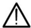
The maximum input DC voltage is 600V. Do not measure voltages exceeding the limits given in this manual. Exceeding voltage limits could result in electrical shocks to the user and damage to the instrument.
Fig. 3: Use of the instrument for DC voltage measurement
- Select position ¥
- Insert the red cable into input terminal VHz% m ACAP +· and the black cable into input terminal COM.
- Position the red lead and the black lead respectively in the spots with positive and negative potential of the circuit to be measured (see Fig. 3). The display shows the value of voltage.
- If the display shows the message "O.L", select a higher range.
- When symbol "-" appears on the instrument's display, it means that voltage has the opposite direction with respect to the connection in Fig. 3.
- To use the HOLD, RANGE and MAX MIN functions, see § 4.2
4.3.2. AC Voltage measurement
CAUTION
The maximum input AC voltage is 600V. Do not measure voltages exceeding the limits given in this manual. Exceeding voltage limits could result in electrical shocks to the user and damage to the instrument.
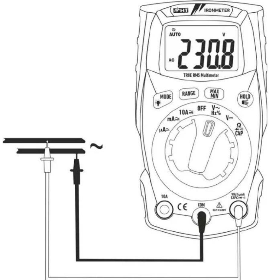
Fig. 4: Use of the instrument for AC voltage measurement
- Select position VHz%\~
- Insert the red cable into input terminal VHz%m_ +···) and the black cable into input terminal COM.
- Position the red lead and the black lead respectively in the spots of the circuit to be measured (see Fig. 4). The display shows the value of voltage.
- If the display shows the message "O.L", select a higher range.
- Press the MODE/ ⚙ key to select measurements "Hz" or "%" in order to display the values of frequency and duty cycle of input voltage.
- To use the HOLD, RANGE and MAX MIN functions, see § 4.2
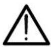
4.3.3. Resistance measurement and Continuity test
CAUTION
Before attempting any resistance measurement, cut off power supply from the circuit to be measured and make sure that all capacitors are discharged, if present.
Fig. 5: Use of the instrument for resistance measurement and continuity test
- Select position CAP.
- Insert the red cable into input terminal VHz% m ACAP +· and the black cable into input terminal COM.
- Position the test leads in the desired spots of the circuit to be measured (see Fig. 5). The display shows the value of resistance.
- If the display shows the message "O.L", select a higher range.
- Press the MODE/ ⚙ key to select “”) measurement, relevant to the continuity test, and position the test leads in the desired spots of the circuit to be measured.
- The value of resistance (which is only indicative) is displayed in and the instrument sounds if the value of resistance is < 50
- To use the HOLD, RANGE and MAX MIN functions, see § 4.2
4.3.4. Diode test
CAUTION

Before attempting any resistance measurement, cut off power supply from the circuit to be measured and make sure that all capacitors are discharged, if present.

Fig. 6: Use of the instrument for diode test
- Select position Ω▶+)))CAP.
- Press the MODE/ ⚙ key to select “▶+” measurement.
- Insert the red cable into input terminal VHz%mμACAPΩ→+·) and the black cable into input terminal COM.
- Position the leads at the ends of the diode to be tested (see Fig. 6), respecting the indicated polarity.
- The value of directly polarized threshold voltage, given in mV, is shown on the display.
- If threshold value is equal to 0mV, the P-N junction of the diode is short-circuited.
- If the display shows the message "O.L", the terminals of the diode are reversed with respect to the indication given in Fig. 6 or the P-N junction of the diode is damaged
4.3.5. Capacitance measurement
CAUTION
Before carrying out capacitance measurements on circuits or capacitors, cut off power supply from the circuit being tested and let all capacitance in it be discharged. When connecting the multimeter and the capacitance to be measured, respect the correct polarity (when required).
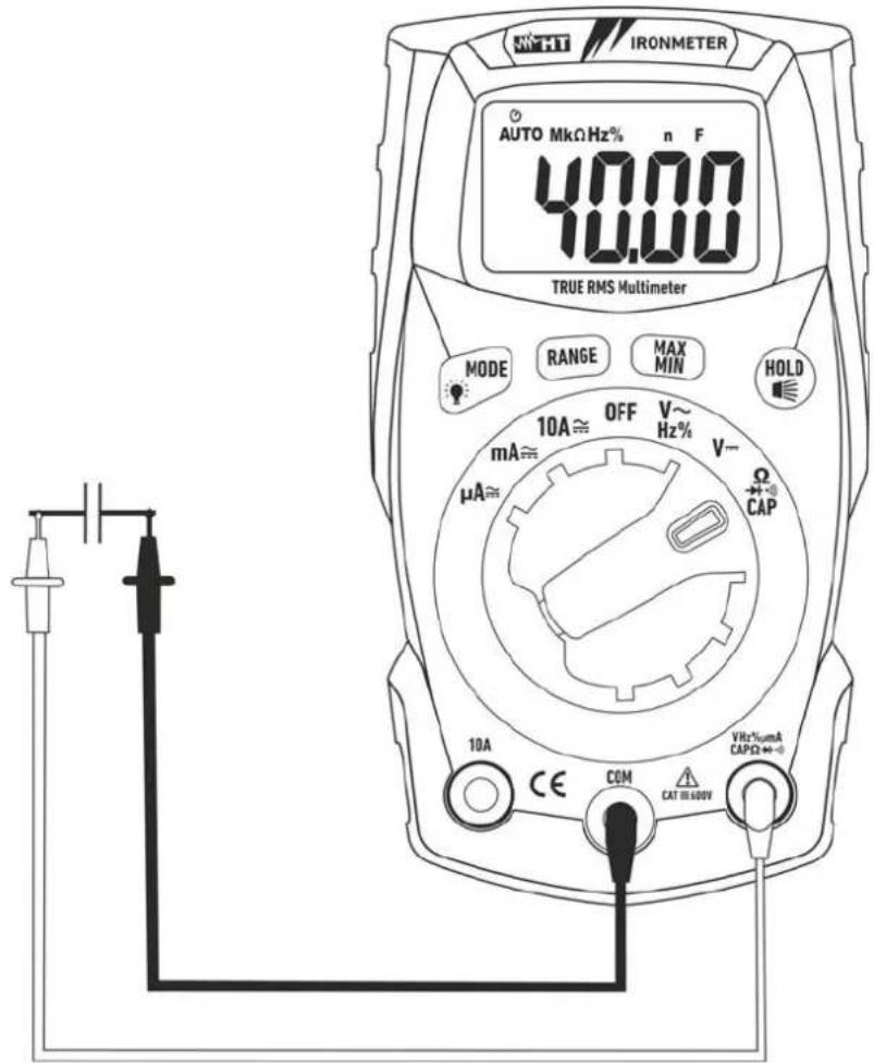
Fig. 7: Use of the instrument for capacitance measurement
- Select position ΩCAP▶+•)
- Press the MODE/ key to select "nF" measurement
- Insert the red cable into input terminal VHz%mμACAPΩ→+))) and the black cable into input terminal COM
- Position the leads at the ends of the capacitor to be tested, respecting, if necessary, the positive (red cable) and negative (black cable) polarity (see Fig. 7). The display shows the value of capacitance
- The message "O.L." indicates that the value of capacitance exceeds the maximum measurable value
- To use the HOLD function, see § 4.2
4.3.6. DC Current measurement
CAUTION

Maximum input DC current is 10A (input 10A) or 400mA (input VHz%mμACAPΩ→+·)). Do not measure currents exceeding the limits given in this manual. Exceeding voltage limits could result in electrical shocks to the user and damage to the instrument.
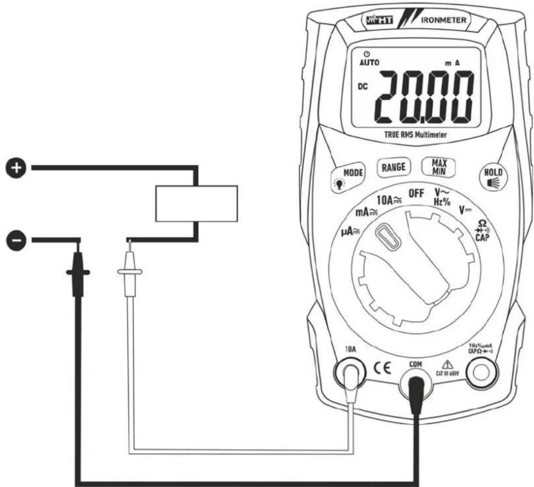
Fig. 8: Use of the instrument for DC current measurement
- Cut off power supply from the circuit to be measured.
- Select positions"μA≈", "mA≈" or "10A≈"
- Press the MODE/ 🔊 key to select "DC" measurement.
- Insert the red cable into input terminal 10A or into input terminal VHz% m ACAP +·)) and the black cable into input terminal COM.
- Connect the red lead and the black lead in series to the circuit whose current you want to measure, respecting polarity and current direction (see Fig. 8).
- Supply the circuit to be measured. The display shows the value of current.
- If the display shows the message "O.L", the maximum measurable value has been reached.
- When symbol "-" appears on the instrument's display, it means that current has the opposite direction with respect to the connection in Fig. 8.
- To use the HOLD, RANGE and MAX MIN functions, see § 4.2
4.3.7. AC Current measurement
CAUTION
Maximum input AC current is 10A (input 10A) or 400mA (input VHz%ΩmAμACAP▶+•). Do not measure currents exceeding the limits given in this manual. Exceeding voltage limits could result in electrical shocks to the user and damage to the instrument.
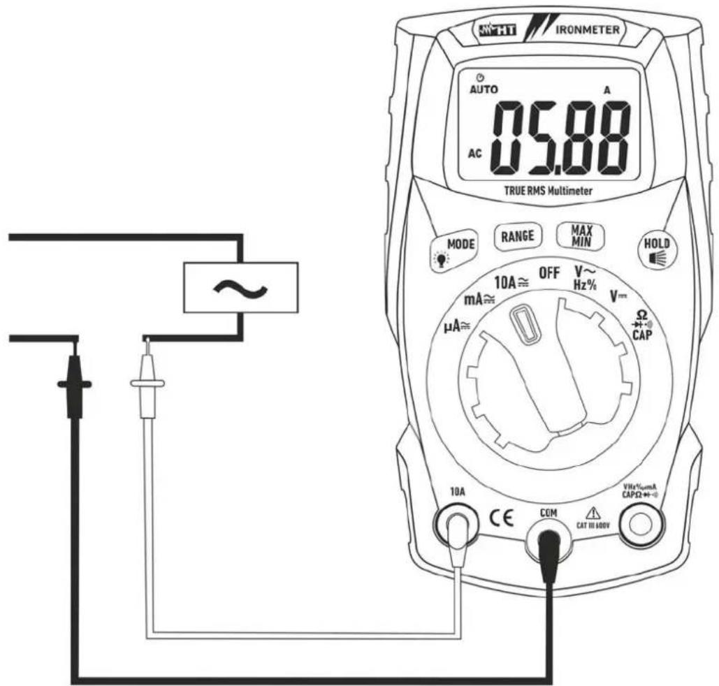
Fig. 9: Use of the instrument for AC current measurement
- Cut off power supply from the circuit to be measured.
- Select positions "μA≈", "mA≈" or "10A≈"
- Insert the red cable into input terminal 10A or into input terminal VHz%mμACAPΩ▶+))) and the black cable into input terminal COM.
- Connect the red lead and the black lead in series to the circuit whose current you want to measure, respecting polarity and current direction (see Fig. 9).
- Supply the circuit to be measured. The display shows the value of current.
- If the display shows the message "O.L", the maximum measurable value has been reached.
- To use the HOLD, RANGE and MAX MIN functions, see § 4.2
5. MAINTENANCE
CAUTION
- Only expert and trained technicians should perform maintenance operations. Before carrying out maintenance operations, disconnect all cables from the input terminals.
- Do not use the instrument in environments with high humidity levels or high temperatures. Do not expose to direct sunlight.
- Always switch off the instrument after use. In case the instrument is not to be used for a long time, remove the battery to avoid liquid leaks that could damage the instrument's internal circuits.
5.1. REPLACING THE BATTERIES AND THE INTERNAL FUSES
When the display shows “+ -” it is necessary to replace the battery.
Replacing the battery
- Turn the rotary switch to OFF.
- Remove the cables from the input terminals.
- Loosen the fastening screw of the battery compartment cover on the top rear part of the instrument and remove the cover.
- Remove all batteries and replace them with new batteries of the same type (see § 6.1.2), respecting the indicated polarity.
- Restore the battery compartment cover into place and fasten it by means of the relevant screw.
- Do not scatter old batteries into the environment. Use the relevant containers for disposal.
Replacement of fuses
- Position the rotary switch to OFF and remove the cables from the input terminals.
- Loosen the fastening screw of the fuse compartment cover under the instrument's stand and remove the cover.
- Remove the damaged fuse, insert a new fuse of the same type (see § 6.1.2) and close the fuse compartment again.
5.2. CLEANING THE INSTRUMENT
Use a soft and dry cloth to clean the instrument. Never use wet cloths, solvents, water, etc.
5.3. END OF LIFE

WARNING: the symbol on the instrument indicates that the appliance and its accessories must be collected separately and correctly disposed of.
6. TECHNICAL SPECIFICATIONS
6.1. TECHNICAL CHARACTERISTICS
Accuracy calculated as [%reading + (num. digits*resolution)] at 18°C ÷ 28°C <75%HR
DC Voltage
| Range | Resolution | Accuracy | Input impedance | Protection against overcharge |
| 400.0mV | 0.1mV | ±(1.0%rdg + 3digits) >10MΩ | 600VDC/ACrms | |
| 4.000V | 0.001V | |||
| 40.00V | 0.01V | |||
| 400.0V | 0.1V | |||
| 600V | 1V |
AC TRMS Voltage
| Range | Resolution | Accuracy (*) (50÷60Hz) | Input impedance | Protection against overcharge |
| 4.000V | 0.001V | ±(1.0%rdg + 3digits) >10MΩ | 600VDC/ACrms | |
| 40.00V | 0.01V | |||
| 400.0V | 0.1V | |||
| 600V | 1V | |||
(*) Accuracy specified from 5% to 100% of the measuring range.
Frequency measuring range: 50Hz ÷ 60Hz (arbitrary waveform), 45Hz ÷ 1kHz (sinusoidal waveform)
Crest factor: ≤3 (up to 300V), ≤1.5 (up to 600V)
DC Current
| Range | Resolution | Accuracy | Protection against |
| 400.0μA | 0.1μA | ±(1.0%rdg + 3digits) | Fast fuse 500mA/600V |
| 4000μA | 1μA | ||
| 40.00mA | 0.01mA | ||
| 400.0mA | 0.1mA | ||
| 4.000A | 0.001A | ±(1.2%rdg + 3digits) | Fast fuse 10A/600V |
| 10.00A (*) | 0.01A |
(*) 20A for max 30s with not declared accuracy
AC TRMS Current
| Range | Resolution | Accuracy (*) (50÷60Hz) | Protection against overcharge |
| 400.0μA | 0.1μA | ±(1.2%rdg + 3digits) | Fast fuse 500mA/600V |
| 4000μA | 1μA | ||
| 40.00mA | 0.01mA | ||
| 400.0mA | 0.1mA | ||
| 4.000A | 0.001A | ±(1.8%rdg + 5digits) | Fast fuse 10A/600V |
| 10.00A (**) | 0.01A |
(*) Accuracy specified from 5% to 100% of the measuring range
(**) 20A for max 30s with not declared accuracy
Diode test
| Function Test current Max voltage with open circuit | ||
| <0.35mA | 3VDC | |
Resistance and Continuity test
| Range | Resolution | Accuracy | Buzzer | Protection against overcharge |
| 400.0Ω | 0.1Ω | ±(1.5%rdg + 5digits) | <50Ω | 600VDC/ACrms |
| 4.000kΩ | 0.001kΩ | |||
| 40.00kΩ | 0.01kΩ | |||
| 400.0kΩ | 0.1kΩ | |||
| 4.000MΩ | 0.001MΩ | |||
| 40.00MΩ | 0.01MΩ | ±(2.5%rdg + 20digits) |
Frequency (electronic circuits)
| Range | Resolution | Accuracy | Sensitivity: |
| 10.00Hz ÷ 10kHz | 0.01Hz | ±(1.2%rdg) | 15Vrms |
Duty Cycle
| Range | Resolution | Accuracy |
| 0.1% ÷ 99.9% | 0.1% | ±(1.2%rdg + 2digits) |
Pulse frequency range: 5Hz ÷ 150kHz, Pulse amplitude: 100μs ÷ 100ms
Capacitance
| Range | Resolution | Accuracy | Protection against |
| 40.00nF | 0.01nF | ±(4.5%rdg + 10digits) | 600VDC/ACrms |
| 400.0nF | 0.1nF | ||
| 4.000μF | 0.001μF | ±(3.0%rdg + 5digits) | |
| 40.00μF | 0.01μF | ||
| 400.0μF | 0.1μF | ||
| 4000μF | 1μF | ±(5.0%rdg + 5digits) |
overcha
6.1.1. Reference standards
Safety: IEC/EN61010-1 EMC: IEC/EN61326-1
Insulation: double insulation
Pollution level: 2
Measurement category: CAT III 600V
Max operating altitude: 2000m (6562ft)
Drop test: 3m
6.1.2. General characteristics
Mechanical characteristics
Size (L x W x H): 120 x 65 x 45mm (5 x 3 x 2in)
Weight (batteries included): 200g (7ounces)
Power supply
Battery type: 2x1.5V batteries type AAA IEC LR03
Low battery indication: the symbol
Auto Power OFF: after 15 minutes
Fuses: F10A/600V, 5 x 20mm (input 10A)
"appears on the display 'idling (may be disabled)
F500mA/600V, 5 x 20mm (input mAμA)
Display
Conversion: TRMS
Characteristics: 4 LCD, 4000 dots plus decimal sign, point and backlight
Sampling frequency: 3times/s
6.2. ENVIRONMENT
6.2.1. Environmental conditions for use
Reference temperature: 18^ ÷ 28^ ( 64^ ÷ 82^ )
Operating temperature: 5^ ÷ 40^ ( 41^ ÷ 104^ )
Allowable relative humidity: <80%HR
Storage temperature: -20^ ÷ 60^ (-4^ ÷ 140^)
Storage humidity: <80%HR
This instrument satisfies the requirements of Low Voltage Directive 2014/35/EC (LVD) and of EMC Directive 2014/30/EC
This instrument satisfies the requirements of European Directive 2011/65/EU (RoHS) and 2012/19/EU (WEEE).
6.3. ACCESSORIES
6.3.1. Accessories provided
- Pair of test leads
- Batteries
- Carrying case
- User manual
7. ASSISTANCE
7.1. WARRANTY CONDITIONS
This instrument is warranted against any material or manufacturing defect, in compliance with the general sales conditions. During the warranty period, defective parts may be replaced. However, the manufacturer reserves the right to repair or replace the product.
Should the instrument be returned to the After-sales Service or to a Dealer, transport will be at the Customer's charge. However, shipment will be agreed in advance. A report will always be enclosed to a shipment, stating the reasons for the product's return. Only use original packaging for shipment. Any damage due to the use of non-original packaging material will be charged to the Customer. The manufacturer declines any responsibility for injury to people or damage to property.
The warranty shall not apply in the following cases:
• Repair and/or replacement of accessories and battery (not covered by warranty).
- Repairs that may become necessary as a consequence of an incorrect use of the instrument or due to its use together with non-compatible appliances.
• Repairs that may become necessary as a consequence of improper packaging.
- Repairs which may become necessary as a consequence of interventions performed by unauthorized personnel.
- Modifications to the instrument performed without the manufacturer's explicit authorization.
- Use not provided for in the instrument's specifications or in the instruction manual.
The content of this manual cannot be reproduced in any form without the manufacturer's authorization.
Our products are patented and our trademarks are registered. The manufacturer reserves the right to make changes in the specifications and prices if this is due to improvements in technology.
7.2. ASSISTANCE
If the instrument does not operate properly, before contacting the After-sales Service, please check the conditions of battery and cables and replace them, if necessary. Should the instrument still operate improperly, check that the product is operated according to the instructions given in this manual. Should the instrument be returned to the After-sales Service or to a Dealer, transport will be at the Customer's charge. However, shipment will be agreed in advance. A report will always be enclosed to a shipment, stating the reasons for the product's return. Only use original packaging for shipment; any damage due to the use of non-original packaging material will be charged to the Customer.
ESPAÑOL
Poids (piles incluses): 200g
Alimentation
Type de pile: 2 piles de 1.5V de type AAA IEC LR03
3145 Bordentown Avenue W3
08859 Parlin - NJ - USA
Tel: +1 719 421 9323
eMail: sales@ht-instruments.us
Web: www.ht-instruments.com