VC191 - Multimeter VOLTCRAFT - Free user manual and instructions
Find the device manual for free VC191 VOLTCRAFT in PDF.
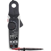
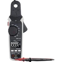
| Product Type | Digital multimeter (DMM) |
| Brand | Voltcraft |
| Model | VC191 |
| Measurement category | CAT III 600 V |
| Display | 6000 counts |
| Dimensions (L x H x D) | 76.5 x 157.5 x 40 mm |
| Weight (without battery) | 262 g |
| Power supply | 9 V block battery (6F22, NEDA 1604) |
| Main functions | AC/DC voltage measurement, AC/DC current, resistance, capacitance, frequency, duty cycle, temperature, diode test, continuity test, NCV test |
| Additional functions | Hold, peak value, MAX/MIN, relative value, auto power off, backlight, flashlight, auto/manual range |
| DC voltage accuracy | ±(1.0% + 8) for 600.0 mV; ±(1.0% + 5) for other ranges |
| AC voltage accuracy | ±(1.5% + 5) for 600.0 mV; ±(1.3% + 4) for other ranges |
| Temperature range | -40 to +400 °C (-40 to +752 °F) |
| Protection fuses | F1: FF 10 A H 600 V; F2: FF 600 mA H 600 V |
| Battery life | Approximately 35 hours (backlight on, flashlight and buzzer off) |
| Maintenance | Clean with dry cloth; calibration recommended once a year; replace battery if low battery symbol appears |
| Operating temperature | 0 to 40 °C |
| Operating humidity | ≤75% RH (0-30 °C), ≤50% RH (30-40 °C), non-condensing |
| Maximum altitude | 2000 m |
| Warranty | See manufacturer's terms |
Frequently Asked Questions - VC191 VOLTCRAFT
User questions about VC191 VOLTCRAFT
0 question about this device. Answer the ones you know or ask your own.
Ask a new question about this device
Download the instructions for your Multimeter in PDF format for free! Find your manual VC191 - VOLTCRAFT and take your electronic device back in hand. On this page are published all the documents necessary for the use of your device. VC191 by VOLTCRAFT.
USER MANUAL VC191 VOLTCRAFT
GB Operating Instructions
VC191 Digital Multimeter
Item No. 2446475 Page 38 - 71
F Notice d'emploi
text_image
QR code image containing encoded data, no visible human-readable text3. Symbol-Erklärung
text_image
VOLTIGR4FT- Introduction....40
- Explanation of symbols ....40
- Intended use....41
- Delivery content....41
- Features and functions....41
- Up-to-date operating instructions 42
- Safety instructions 42
a) General information....42
b) Connected devices....43
c) Fuse 43
d) (Rechargeable) batteries....43
e) Multimeter....44
f) Probes....45
- Operating elements 46
a) Overview 46
b) Dial....47
- Display and symbols 48
- Insert / replace batteries....49
- Operation....49
a) Power ON....49
b) DC/AC voltage Measurement....50
c) LoZ AC voltage measurement....51
d) Resistance measurement (Ω) 52
e) Continuity test ( ·s )....53
f) Diode test (▶)....54
g) Capacity measurement ....55
h) Frequency (>10 Hz) / duty ratio measurement (%) 56
i) Temperature measurement....57
j) Current measurement / Frequency (999.9 Hz to 9.999 kHz) ....58
k) Non-contact AC voltage test "NCV" 59
12. Additional functions ....59
a) Access sub functions....59
b) Range....60
c) Hold / 📄 ⇌ (torch)....60
d) Peak....60
e) Maximum / Minimum....61
f) Automatic power off....61
g) Relative value....62
13. Replacing the Fuse ....62
14. Troubleshooting....62
15. Cleaning and maintenance....63
a) Cleaning....63
b) Maintenance....63
16. Disposal....64
a) Product....64
b) (Rechargeable) batteries....64
17. Technical data ....65
a) General....65
b) Fuses....66
c) Measurement tolerances....66
d) Capacitance measurement....66
e) Continuity ( ) and diode ( ) test....67
f) DC voltage measurement....67
g) AC voltage measurement....68
h) Resistance measurement (Ω) 69
i) Frequency / duty ratio measurement....69
j) DC current measurement....70
k) Temperature measurement....70
I) AC current measurement....71
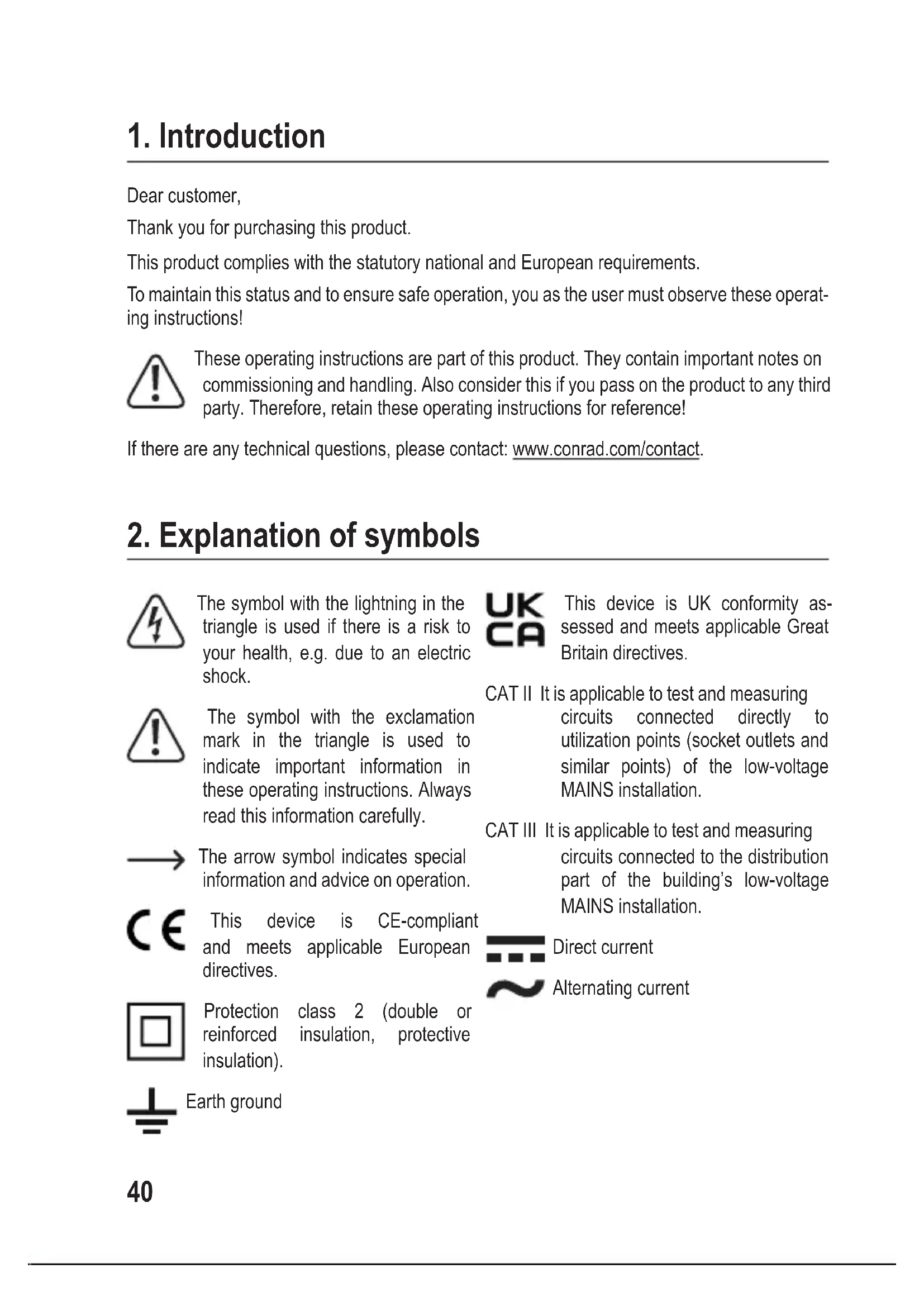
1. Introduction
Dear customer,
Thank you for purchasing this product.
This product complies with the statutory national and European requirements.
To maintain this status and to ensure safe operation, you as the user must observe these operating instructions!

These operating instructions are part of this product. They contain important notes on commissioning and handling. Also consider this if you pass on the product to any third party. Therefore, retain these operating instructions for reference!
If there are any technical questions, please contact: www.conrad.com/contact.
2. Explanation of symbols
The symbol with the lightning in the triangle is used if there is a risk to your health, e.g. due to an electric shock.

The symbol with the exclamation mark in the triangle is used to indicate important information in these operating instructions. Always read this information carefully.
The arrow symbol indicates special information and advice on operation.

This device is CE-compliant and meets applicable European directives.

Protection class 2 (double or reinforced insulation, protective insulation).
Earth ground

This device is UK conformity assessed and meets applicable Great Britain directives.
CAT II It is applicable to test and measuring circuits connected directly to utilization points (socket outlets and similar points) of the low-voltage MAINS installation.
CAT III It is applicable to test and measuring circuits connected to the distribution part of the building's low-voltage MAINS installation.

Direct current
Alternating current
3. Intended use
The product is intended to be used as a digital multimeter (DMM), measured values are shown on a digital display. The DMM can be used for professional, industrial and do-it-yourself applications up to CAT III. It is intended for indoor use only. Contact with moisture must be avoided under all circumstances.
For safety and approval purposes, you must not rebuild and/or modify this product. If you use the product for purposes other than those described above, the product may be damaged. In addition, improper use can result in short circuits, fires, electric shocks or other hazards. Read the instructions carefully and store them in a safe place. Make this product available to third parties only together with its operating instructions.
All company names and product names are trademarks of their respective owners. All rights reserved.
4. Delivery content
- Digital multimeter
- Test leads (pair)
-
Point contact temperature probe
-
9 V block battery
- Operating instructions
5. Features and functions
• AC / DC voltage measurement
• AC / DC current measurement up to 10 A.
- Duty cycle
- Diode test
• Acoustic continuity tester
- Hold function
- Auto power off.
- Backlight
- Peak reading (PEAK)
- 6000 counts
- True RMS
- Auto range
- 600 V high performance fuses
• CAT III 600 V measuring category - Torch
6. Up-to-date operating instructions
Download the latest operating instructions at www.conrad.com/downloads or scan the QR code shown. Follow the instructions on the website.

text_image
QR code image containing encoded data, no visible human-readable text7. Safety instructions

Read the operating instructions carefully and especially observe the safety information. If you do not follow the safety instructions and information on proper handling in this manual, we assume no liability for any resulting personal injury or damage to property. Such cases will invalidate the warranty/guarantee.
a) General information
- The device is not a toy. Keep it out of the reach of children and pets.
- Do not leave packaging material lying around carelessly. This may become dangerous playing material for children.
- Protect the appliance from extreme temperatures, direct sunlight, strong jolts, high humidity, moisture, flammable gases, steam and solvents.
- Do not place the product under any mechanical stress.
- If it is no longer possible to operate the product safely, take it out of operation and protect it from any accidental use. Safe operation can no longer be guaranteed if the product:
- is visibly damaged,
- is no longer working properly,
- has been stored for extended periods in poor ambient conditions or
- has been subjected to any serious transport-related stresses.
- Please handle the product carefully. Jolts, impacts or a fall even from a low height can damage the product.
- Consult an expert when in doubt about the operation, safety or connection of the appliance.
-
Maintenance, modifications and repairs must only be completed by a technician or an authorised repair centre.
-
If you have questions which remain unanswered by these operating instructions, contact our technical support service or other technical personnel.
- In commercial institutions, the accident prevention regulations of the Employer's Liability Insurance Association for Electrical Systems and Operating Materials are to be observed.
- In schools, training centres, computer and self-help workshops, handling of meters must be supervised by trained personnel in a responsible manner.
- Before each use verify tester operation by measuring a known voltage.
b) Connected devices
- Observe the safety and operating instructions of any other devices which are connected to the product.
c) Fuse
- A defective fuse must be replaced with a new fuse with the same specifications. Do not repair or bridge a defective fuse, as this may cause a fire or result in fatal electric shock!
d) (Rechargeable) batteries
- Correct polarity must be observed while inserting the (rechargeable) battery.
- The (rechargeable) batteries should be removed from the device if it is not used for a long period of time to avoid damage through leaking. Leaking or damaged (rechargeable) batteries might cause acid burns when in contact with skin, therefore use suitable protective gloves to handle corrupted (rechargeable) batteries.
- (Rechargeable) batteries must be kept out of reach of children. Do not leave (rechargeable) batteries lying around, as there is risk, that children or pets swallow them.
- All (rechargeable) batteries should be replaced at the same time. Mixing old and new (rechargeable) batteries in the device can lead to (rechargeable) battery leakage and device damage.
- (Rechargeable) batteries must not be dismantled, short-circuited or thrown into fire. Never recharge non-rechargeable batteries. There is a risk of explosion!
e) Multimeter
- Do not switch the meter on after it has been taken from a cold to a warm environment. The condensation that forms might destroy the device. Allow the device to reach room temperature before switching it on.
- Check that the multimeter is set to the correct function before each measurement.
- To avoid electric shock, do not touch the connections/measuring points directly or indirectly during measurement. Check the meter for damage before each measurement. Never carry out any measurements if the protecting insulation is defective (torn, ripped off etc.)
- Do not use during thunderstorms.
- Never operate the product in direct proximity of strong magnetic or electromagnetic fields or transmitter aerials or HF generators. This could affect measurement.
- For accurate measurements, replace the battery when the low battery symbol appears on the display.
- Pay attention to the information besides the warning signs at the test lead terminals. The measured voltage or current must not exceed the values shown!
- Never operate the meter when the case is open. !DANGER TO LIFE!
f) Probes
- The probe cables have a wear indicator. When damaged, a second insulation layer in a different colour becomes visible. The measuring accessories must no longer be used and must be replaced.
- During measuring, do not grip beyond the grip range markings indicated on the measuring probes.
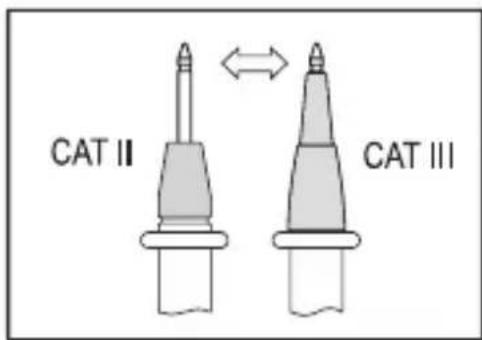
- When using the measuring probes without cover caps, measurements between the meter and the earth potential must not be performed above the measuring category CAT II.
text_image
CAT II CAT III- When measuring in the measuring category CAT III. Measuring probes with cover caps (max. 4 mm free contact length) must be used to avoid accidental short circuits during measurement. They are enclosed.
- The measuring probes must be removed from the measured object each time the measuring function is changed.
- The voltage between the connection points of the meter and the earth potential must not exceed 600 V DC/AC in CAT III.
- Risk of fatal electric shock! Be careful when dealing with voltages higher than AC 30Vr.m.s, 42.4Vpeak or DC 60V.
- Probe assemblies to be used for MAINS measurements should meet EN 61010-031 standard, rated CAT III 600V, 10A or better.
8. Operating elements
a) Overview
text_image
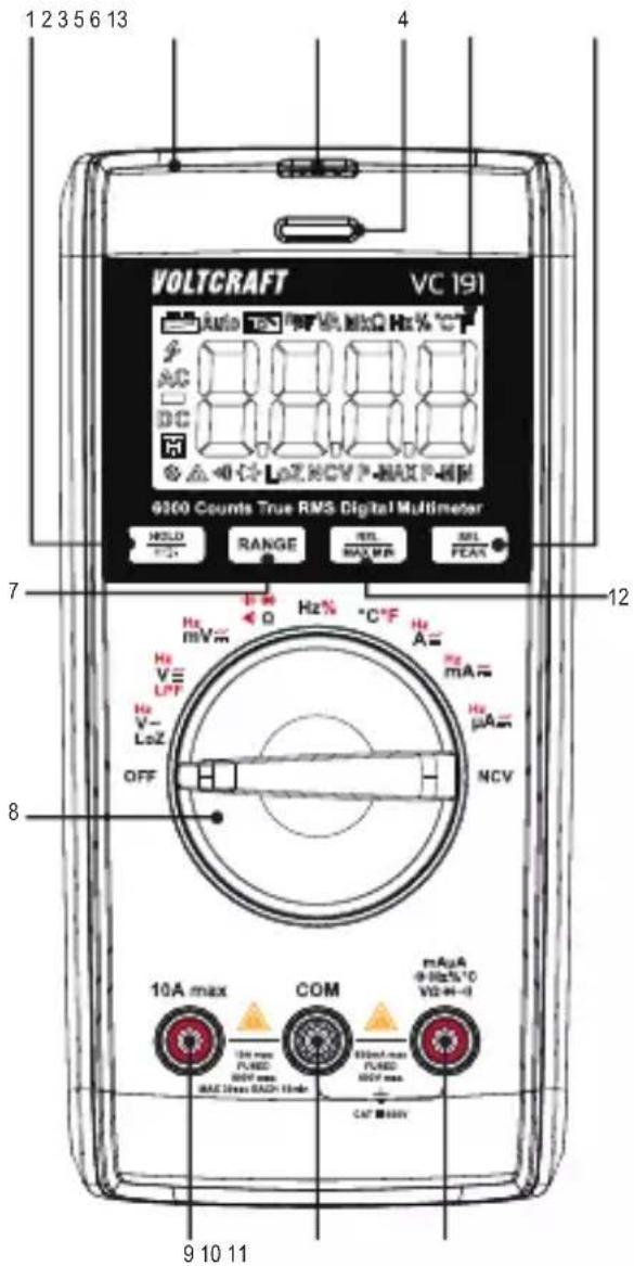
1 2 3 5 6 13 4 VOLTCRAFT VC 191 AC DC 0.00 Hz NCV P-MAX P-HM 9300 Counts True RMS Digital Multimeter HOLD RANGE REL MAX FEA 7 B Hz Hz mV Hz V- LoZ OFF 12 Hz A Hz mA Hz μA NCV 8 10A max COM mAuA 0 Hz NCO VD H- 10A max FLRED RND max MAC Max RAD HmR 0.00A max FLRED RND max CAT MNV 9 10 11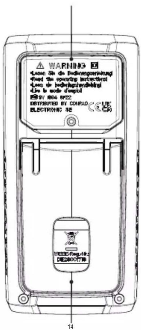
text_image
WARNING Leven Se de Bedingengesinklungs Fixed the operating instructions Leven de bedingengesinklungs Live to node dempel EN 19V 804 6P22 DISTRIBUTED BY CONPAD ELECTRONIC SE WEEEE/Rag-Hk DE25001778 141 HOLD / button
2 Non-contact voltage measuring area
3 Torch
4 Tri-color indicator LED
5 Display
6 SEL/PEAK button
7 RANGE button
8 Function dial
9 10 A max terminal
10 COM terminal
11 terminal
12 REL/MAX MIN button
13 Battery compartment cover
14 Fold-out stand
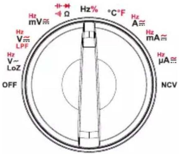
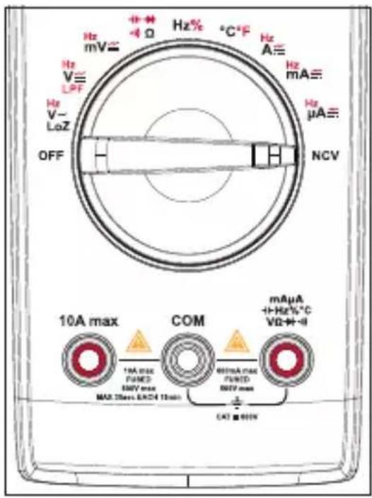
b) Dial
text_image
Hz mV≈ Hz V≈ LPF Hz V~ LoZ OFF +→ -Ω Hz% °C+F Hz A≈ Hz mA≈ Hz μA≈ NCV- Adjust the dial to choose a function.
- Automatic range selection "Auto" is active for most measuring functions.
- Some functions have sub functions, these are marked in red can be accessed by pressing the SEL/PEAK button.
- Always set the dial to "OFF" when not in use.
| Function Description | |
| V, V, mV ≈ | AC/DC voltage measurement |
| Ω | Resistance measurement |
| Diode test | |
| Continuity test | |
| Capacitance measurement | |
| Hz Frequency measurement | |
| % Duty ratio measurement | |
| °C/°F Temperature measurement | |
| μA, mA, ≈ ≈ | AC/DC current |
| LPF V Low pass filter measurement for AC voltage | |
| LoZ V Low impedance measurement for AC voltage | |
| OFF Shutdown | |
| NCV Non-contact AC voltage measurement | |
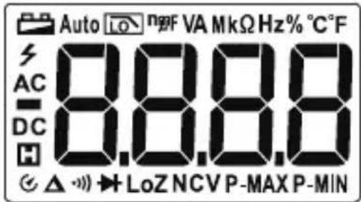
9. Display and symbols
text_image
Auto LO n2F VA MkΩ Hz% °C F AC 8.8.8.8 DC H △ ▼→LoZ NCVP-MAX P-MIN| Icon Description | |
 | Low battery |
 | Auto power off |
| Auto Auto range | |
 | Low pass filter measurement |
| LoZ Low impedance measurement | |
| P-MAX/P-MIN Peak value measurement | |
| MAX/MIN Maximum/Minimum measurement | |
 | Data hold |
 | High voltage |
| AC AC signal | |
| DC DC signal | |
| mV, V Voltage units: millivolt, volt | |
| μA, mA, A Current units: microampere, milliampere, ampere | |
| Ω, kΩ, MΩ Resistance units: ohm, kilo ohm, megaohm | |
| nF, μF, mF Capacitance units: nanofarad, microfarad, millifarad | |
| Hz, kHz, Mhz Frequency units: hertz, kilohertz, megahertz | |
| % Duty ratio measurement | |
| OL Over limit (exceeds max. range) | |
 | Relative value measurement. |
| NCV Non-contact AC voltage measurement | |
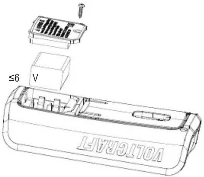
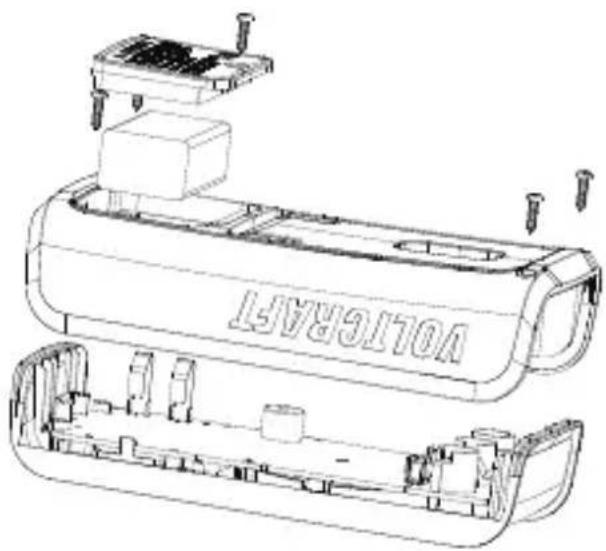
10. Insert / replace batteries

Before opening the rear cover, switch off the power supply and disconnect the test leads from the input terminals and the circuit.
- When the battery voltage is
±0.2 V, the low battery symbol

will be displayed.
- Turn the function dial to the "OFF"
position, and remove the test leads
from the input terminals.
- Unscrew and remove the battery
cover to replace the battery.
text_image
VOLTERTA ≤6 V11. Operation

Replace the battery if the low battery warning ☐ shows. Pay attention to the information besides the warning signs marked on the DMM ☑ beside the test lead terminals. The measured voltage or current must not exceed the values shown!
Test on known voltages to verify that the DMM is functioning correctly.
For accurate measurement results, make sure the probe tips and any areas of contact are free from debris or residue.
a) Power ON
- Turn ON: Set the function dial to the corresponding measurement function.
- Turn OFF: Set the function dial to OFF. Always turn the meter off when it is not in use.
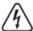
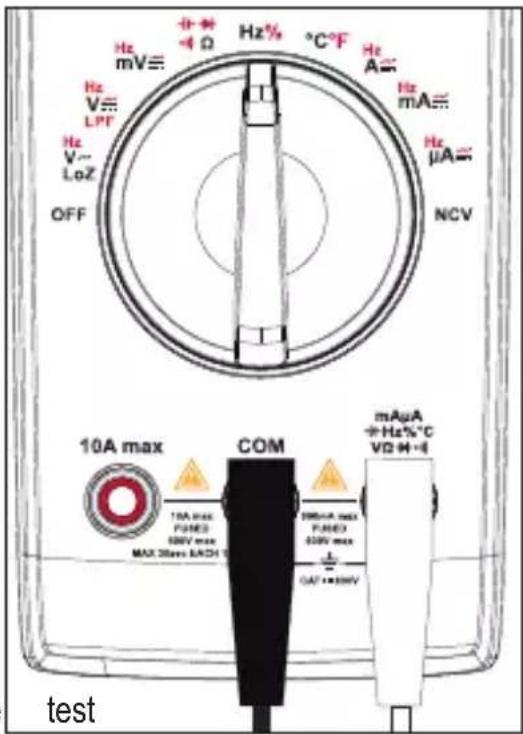
b) DC/AC voltage Measurement
The input impedance is approximately circuit.
10
MΩ and
will
not put
much
strain or
- Set the function dial to the required setting:
- DC voltage measurement (V), “DC” will show on the display.
- Short press RANGE to toggle through ranges (indicated by decimal position).
- AC voltage measurement (V), "AC" will show on the display.
- Short press RANGE to toggle through ranges (indicated by decimal position).
-
Connect the test leads to the terminals:
-
Red test lead to the terminal.
-
Black test lead to the COM terminal.
-
Connect the test lead probes to the correct test points in the circuit:
-
Red: Positive polarity “+”.
-
Black: Negative polarity “-”.
-
Read the voltage values on the display.
- DC voltage measurements (V---): If a minus “-” sign appears in front of the value, the measured voltage is negative (or the measuring lines are swapped).
text_image
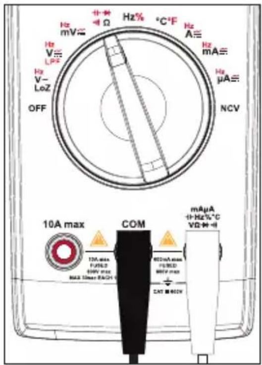
Hz mV≡ + - Ω Hz% °C*F Hz A≡ Hz mA≡ Hz μA≡ NCV 10A max COM 10A max FLAMED 500V max MAX Max DACR 1 600mA max FLAMED 500V max CET ■ BMY mAµA + Hz% °C VD M - €- AC voltage measurements are given in true RMS.

A warning will sound when measured values are out of range >600 V.
- When finished measuring, disconnect the test leads and switch the power OFF.
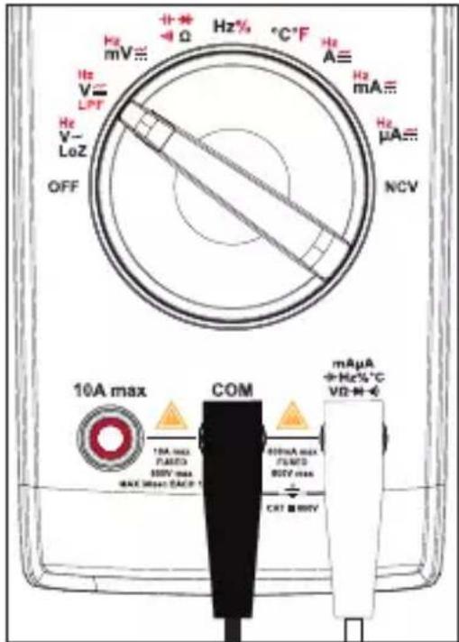
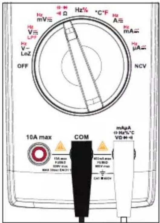
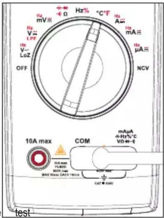
c) LoZ AC voltage measurement
The LoZ measuring function permits alternating “AC” voltage measurements with low impedance (approx. 3 kΩ). The lower internal resistance of the meter reduces measurement discrepancies such as phantom voltages.
The input impedance is approximately 3 kΩ and will put some strain on the circuit.
- Set the function dial to LoZ V.\~
-
Connect the test leads to the terminals:
-
Red test lead to the terminal.
-
Black test lead to the COM terminal.
-
Connect the test lead probes to the correct test points in the circuit:
-
Red: Positive polarity “+”.
-
Black: Negative polarity “-”.
-
Read the voltage values on the display.
-
The displayed value is true RMS.
-
Wait for 3 minutes before next operation.
-
When finished measuring, disconnect the leads and switch the power OFF.
text_image
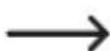
Hz mV≡ Hz% -Ω Hz% °C°F Hz A≡ Hz mA≡ Hz μA≡ NCV Hz V≡ LPF Hz V~ LoZ OFF 10A max COM 10A max TURD PUNED MAX 30mm BACH BUTDA MAX PUNED SMV max CAT ■ MNV mAμA +H-Hz% °C VΩ+0 testd) Resistance measurement (Ω)
Make sure all circuit parts, circuits, components, and other objects of measurement are disconnected from the voltage supply and fully discharged..
- Set the function dial to .
- “Ω” will show on the display.
- Short press RANGE to toggle through ranges (indicated by decimal position).
- Connect the test leads to the terminals:
- Red test lead to the terminal.
- Black test lead to the COM terminal.
- Connect the test lead probes to the correct test points in the circuit:
- Red: Positive polarity “+”.
- Black: Negative polarity “-”.
Check the lines for continuity by connecting the two test leads. The impedance value should be ≤ 0.5 (inherent impedance of the measuring lines). If the value is ≥ 0.5 , check the terminal connections or if there is any damage.
-
Read the resistance values on the display.
-
"OL" will appear on the display if the maximum range is exceeded or if the circuit is open.
-
When measuring high resistance, it is normal to take a few seconds for readings to stabilize.
-
When finished measuring, disconnect the test leads and switch the power OFF
text_image
Hz mV Hz V L Hz V- LoZ OFF 10A max COM 10A max FUSED 68kV max MAX 10ms MAX RACH Hz% °C-F Hz A Hz mA Hz μA NCV mAµA +Hz%°C VD+H+Ie) Continuity test (·)
Make sure all circuit parts, circuits, components, and other objects of measurement are disconnected from the voltage supply and fully discharged.
- Set the function dial to
- Short press the SEL/PEAK button 1x to select continuity test, “.” will show on the display.

-
Connect the test leads to the terminals:
-
Red test lead to the terminal.
-
Black test lead to the COM terminal.
-
Connect the test lead probes to the correct test points in the circuit.
-
A resistance of ≤ 10 is considered and a beep will sound.
-
The measuring range is ≤ 600
-
"OL" will appear on the display if the maximum range is exceeded or if the circuit is open.
-
When finished measuring, disconnect the leads and switch the power OFF.

text_image
Hz mV Hz V LPF Hz V- LoZ OFF Hz% -Ω Hz% °C°F Hz A≡ Hz mA≡ Hz μA≡ NCV continuity, COM mAuA +Hz%°C VD-M=€ 10A max 10A max PUBD MNV max MAX Max Max PADS 600mA max PUBD 600M max CAT 800V testf) Diode test (▶+
Make sure all circuit parts, circuits, components, and other objects of measurement are disconnected from the voltage supply and fully discharged.
The test voltage is approximately 3V.
-
Set the function dial to +-
-
Short press the SEL/PEAK button 3x to select diode test, "→will show on the display.
-
Connect the test leads to the terminals:
- Red test lead to the + terminal.
- Black test lead to the COM terminal.
-
Check the lines for continuity by connecting the two test leads. The value should be approximately 0.000 V.
-
Connect the test lead probes to the correct test points on the diode.
- "OL" will appear on the display if the polarity is reversed or if the circuit is open.
- The normal PN junction forward voltage is approx. 500 to 800 mV.
text_image
Hz mV≡ Ω Hz% °C-F Hz A≡ Hz mA≡ Hz μA≡ NCV 10A max COM mAµA +/-Hz%°C VD-+/-I 10A max PUBSD 329V max MAX 5max EACH 600mA max PUBSD MCV max CAT ■ 600V- When finished measuring, disconnect the test leads and switch the power OFF.
g) Capacity measurement
Make sure all circuit parts, circuits, components, and other objects of measurement are disconnected from the voltage supply and fully discharged.
Always observe polarity with electrolyte capacitors.
- Set the function dial to

-
Short press the SEL/PEAK button 2x to select capacity measurement, "nF" unit or capacitance will show on the display.
-
Connect the test leads to the terminals:
- Red test lead to the terminal.
- Black test lead to the COM terminal.
- Connect the test lead probes to the correct test points on the capacitor.
- Always observe the polarity with electrolyte capacitors.
- "OL" will appear on the display if the polarity is reversed or if the circuit is shorted.
- Wait until the displayed value has stabilized. This may take a few seconds for capacities >60 F.
text_image
Hz mV≡ Hz V~ LPF Hz V~ LoZ OFF + - Φ Ω Hz% °C°F Hz A= Hz mA≡ Hz μA≡ NCV 10A max COM mAµA +Hz%°C VΩ·M-4 *EA max Pc/MD MCV max MAX 20mm MAX 3.5 000mA max Pc/MD 000V max CFI ■ 100V- When finished measuring, disconnect the test leads and switch the power OFF.
h) Frequency (>10 Hz) / duty ratio measurement (%)

This measuring function is not suitable for measuring mains current!
The DMM can be used to measure and indicate signal voltage frequencies up to 1 MHz.
The maximum input amplitude is 30 Vrms.
Please observe the input values in the technical data.
- Set the function dial to Hz% , Hz will appear on the display.
- Short press the SEL/PEAK button to switch between frequency "Hz" and duty ratio "%" measurement.
-
Connect the test leads to the terminals:
-
Red test lead to the terminal.
-
Black test lead to the COM terminal.
-
Connect the test lead probes to the correct test points in the circuit.
Duty ratio: The pulse duration of the positive half wave is displayed as a percentage. 50% is displayed for a symmetrical signal.
- When finished measuring, disconnect the leads and switch the power OFF.
text_image
Hz mV≡ Hz V≡ LPT Hz V~ LoZ OFF 10A max COM 10A max PUMED 500V max MAX 30ms MAX 1 mAμA +Hz%°C VD +H+I mAμA +Hz%°C VD +H+I testi) Temperature measurement

Do not get the temperature probe wet!
- Set the function dial to ^ C°F.
-
Short press the SEL/PEAK button to select a unit of measurement, "°C" or "°F" will show on the display.
-
Connect the K-type thermocouple to the terminals.
-
"TEMP +" plug to the terminal.
-
"COM -" plug to the COM terminal.
-
Measure the temperature at the probe tip.
-
"OL" will appear on the display when the DMM is turned on.
-
The measured temperature should be < 400 °C / 752 °F (°F = °C × 1.8 + 32)
-
When finished measuring, disconnect the leads and switch the power OFF.
text_image
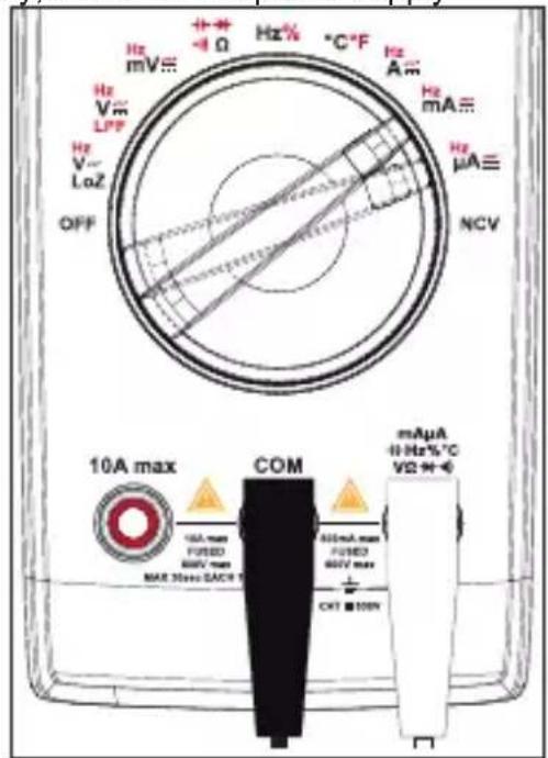
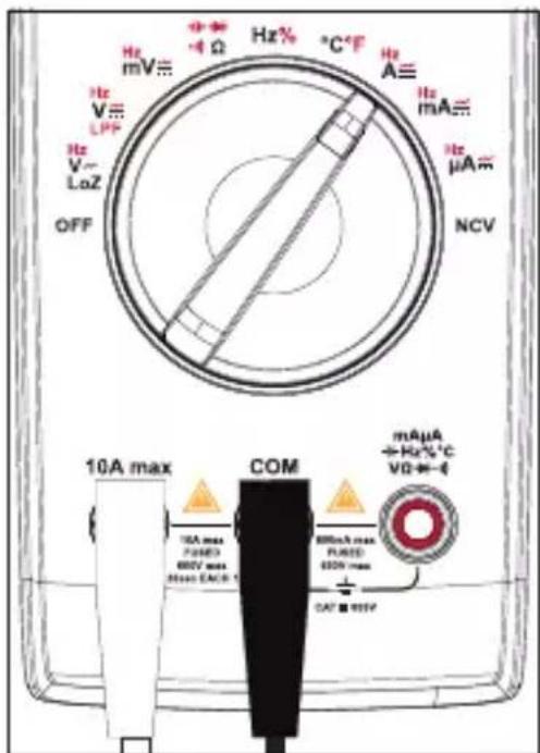
Hz mV Hz V LPP Hz V LoZ OFF Hz% °C-F Hz A Hz mA Hz μA NCV 10A max COM mAµA +Hz%°C VD+- SEA max PLUMB DCF max MAX 300A (ACB 100A) CAT 400V testj) Current measurement / Frequency (999.9 Hz to 9.999 kHz)

This measuring function is suitable for measuring mains current.
To prevent possible electric shock, fire or personal injury, switch off the power supply
of the circuit, and then connect the DMM to the circuit in series before measuring the current.
If the range of the measured current is unknown, always start at the highest measurement range and switch down to lower ranges if needed.
There are fuses inside "10 A" and "mA μA" input terminals. Do not connect the test leads to circuits in parallel.
A warning will sound when measured values are out of range >10 A.
Measuring >5 A must only be performed for max. 30 seconds and at 15 minute intervals.
text_image
Hz mV≡ + - + - -4 Ω Hz % °C °F Hz A≡ Hz mA≡ Hz μA≡ NCV 10A max COM mAµA +1 Hz-%°C V2 + + - 10A max FUSED MAX 30ms DACB 600mA max FUSED MAX 30ms DACB CKT ■ 100kV- Set the function dial to A , mA , or A , the corresponding unit of measurement will appear on the display.
- Short press the SEL/PEAK button to cycle through "DC", "AC", "Hz".
-
Connect the test leads to the terminals:
-
Red test lead to the -10A max terminal.
-
Black test lead to the COM terminal.
-
Connect the test lead probes to the circuit in series.
-
Read the value on the display.
-
DC current: The polarity is shown together with the measured value.
- AC current: Values are given in true RMS.
-
Frequency: Measuring range is 999.9 Hz to 9.999 kHz (input amplitude ≥ range × 50 %).
-
When finished measuring, disconnect the test leads, power the circuit down and switch the DMM power OFF.
text_image
Hz mV≡ -4 Ω Hz% °C°F Hz A≡ Hz mA≡ Hz μA≡ NCV 10A max COM mAµA +Hz%°C V0←- 10A max PUMED 600V max MAX EACH 1 800mA max PUMED 600V max 0.57 ± 95%k) Non-contact AC voltage test "NCV"
Make sure that all measuring sockets are unoccupied. Please remove all measuring leads and adapters from the measuring device.
This function only serves as an aid. Prior to performing work on these cables, you must perform contact measuring operations to check for the absence of voltage.
Test this function beforehand on a known AC voltage source.
- Set the function dial to NCV, "EF" and "NCV" will show on the display.
-
Guide the non-contact voltage sensor area to the test location (max. 5 mm). For twisted cables, it is recommended to touch the cable with the end of non-contact voltage sensor.
-
If AC power is sensed, the tri-color indicator LED will light up and the buzzer will sound.
- The higher the voltage, the higher the frequency at which the buzzer will beep.
-
The tri-color indicator LED will change from green to yellow to red as the voltage increases.
-
When finished measuring, switch the power OFF.
text_image
Hz mV= Hz V~ LPF Hz V~ LoZ OFF 10A max COM 10A max (μHz) 50V max MAX 25max, MAX4 15min 60mA max (μHz) 50V max CAT ■ 600W Hz% °C °F Hz A≡ Hz mA≡ Hz μA≡ NCV mAµA +1Hz%°C VΩ+ + + -12. Additional functions

Button press:
Short press = <2 sec.
Long press = >2 sec.
a) Access sub functions
Several measuring functions are assigned sub functions, and are marked in red around the function dial. Short press the SEL/PEAK button to cycle through each sub function.
b) Range
Pressing the RANGE button will switch the DMM from automatic "Auto" range to manual range. This mode is only applicable with the following functions: V\~, V-, Ω, μA\~, mA\~, and A\~
- Enter manual range: Short press the RANGE button.
- "Auto" will disappear from the display.
- Short press RANGE to toggle through ranges (indicated by decimal position).
- Exit manual range: Long press the RANGE button or rotate the function dial, "Auto" will appear on the display.
c) Hold / (torch)
Hold
The hold function keeps the indicated value on the display so you have more time to read or record it.

If you test live wires, make sure this function is deactivated before the measurement starts. Otherwise, the measurement will not be correct.
- Short press the HOLD button to activate/deactivate the hold.
- The symbol will appear to indicate that hold is active.
Torch
Long press the button to switch the torch ON/OFF.
d) Peak
- This function allows users to capture faster signal events than the normal min/max function. Input changes of 1 millisecond or longer will be recorded.
- This mode is only available with the following functions: V\~, mV\~, μA\~, mA\~, and A\~.
- Long press the SEL/PEAK button to enter/exit peak value mode.
- Short press the SEL/PEAK button to cycle through "P-MAX" and "P-MIN" values.
e) Maximum / Minimum
This function permits saving and display of maximum or minimum values during a series of measurements. Auto-range will be deactivated.
- This mode is only applicable with the following functions: LOZV\~, LPFV\~, V\~, V---, mV ≅, Ω, μA≈, mA≈, A≈, and °C/°F.
- Select the proper range before selecting MAX MIN to ensure that the MAX MIN reading will not exceed the measurement range.
- The values are taken from the time MAX MIN mode was entered. Input changes of 100 milliseconds or longer will be recorded.
- Long press the MAX MIN button to enter/exit maximum and minimum measurement mode.
- Short press the MAX MIN button to cycle through measurements:
- Maximum value: MAX will show on the display.
- Minimum value: MIN will show on the display.
f) Automatic power off
Automatic power off is an energy saving feature. When activated, the power will turn off if no activity is detected for approximately 15 mins. Press any button, use the function dial, or restart to wake.
Disable auto-power off
- Set the function dial to the OFF position.
- While pressing and holding the SEL/PEAK button, turn the function dial to any position.
- The symbol will disappear.
Activate auto-power off
- Restart the device by setting the function dial OFF then ON again.
- The symbol will show.
g) Relative value
This stores an existing reading (a delta) and resets the display to zero. It is a relative reference point to measure against the next reading.
- This mode is only applicable with the following functions: LOZV\~, V\~, V-, mV\~, μA\~, mA\~, A , EPFV , , \~°C\~F.
- Short press the REL/MAX MIN button to enter or exit REL measurement function.
• The symbol will show.
13. Replacing the Fuse

Never operate the meter if the case is open. !DANGER TO LIFE!
- Turn the function dial to the "OFF" position.
- Remove the test leads from the input terminals.
- Unscrew then remove the battery cover.
- Unscrew the rear cover screws.
- Replace the fuse with one that is of the same type and specification. Refer to the section "Technical data" for further information.
- Carefully replace the covers.
text_image
VOLI/6R45T14. Troubleshooting
| Problem Possible cause | Suggested solution | |
| The DMM will not power up. | Flat battery Replace with new battery. | |
| Cannot measure changes in value. | Is the wrong measuring function activated (AC/DC)? | Check display (AC/DC) and switch the function if required. |
| Are the incorrect leads used? | Check the terminal assignment or connection of the probe leads. | |
| Is the HOLD function activated? | Deactivate the HOLD function. | |
| No measurement possible in the A measurement range | Is the fuse of the A measuring range defective? | Check the 10 A F1 fuse |
| No measurement possible in the mA/μA measurement range | Is the fuse of the mA/μA measurement range defective? | Check the 0.6 A F2 fuse. |
15. Cleaning and maintenance
a) Cleaning

Do not use aggressive cleaning agents, rubbing alcohol or other chemical solutions as they can cause damage to the housing and malfunctioning.
- Disconnect the product from the mains before each cleaning.
- Clean the product with a dry, fibre-free cloth.
- If there is any malfunction, stop using the meter and send it for maintenance. Maintenance and service must only be carried out by qualified professionals.
b) Maintenance
- The DMM should be calibrated once a year for maximum accuracy.
- The DMM does not require maintenance other than battery and fuse replacement.
- Check the device and measuring lines for signs of wear and damage.
16. Disposal
a) Product
This symbol must appear on any electrical and electronic equipment placed on the EU market. This symbol indicates that this device should not be disposed of as unsorted municipal waste at the end of its service life.
Owners of WEEE shall dispose of it separately from unsorted municipal waste. Spent batteries and accumulators, which are not enclosed by the WEEE, as well as lamps that can be removed from the WEEE in a non-destructive manner, must be removed by end users from the WEEE in a non-destructive manner before it is handed over to a collection point.
Distributors of electrical and electronic equipment are legally obliged to provide free takeback of waste. Conrad provides the following return options free of charge (more details on our website):
• in our Conrad offices
• at the Conrad collection points
- at the collection points of public waste management authorities or the collection points set up by manufacturers or distributors within the meaning of the ElektroG
End users are responsible for deleting personal data from the WEEE to be disposed of. It should be noted that different obligations about the return or recycling of WEEE may apply in countries outside of Germany.
b) (Rechargeable) batteries
Remove batteries/rechargeable batteries, if any, and dispose of them separately from the product. According to the Battery Directive, end users are legally obliged to return all spent batteries/rechargeable batteries; they must not be disposed of in the normal household waste.
Batteries/rechargeable batteries containing hazardous substances are labelled with this symbol to indicate that disposal in household waste is forbidden. The abbreviations for heavy metals in batteries are: Cd = Cadmium, Hg = Mercury, Pb = Lead (name on (rechargeable) batteries, e.g. below the trash icon on the left).
Used (rechargeable) batteries can be returned to collection points in your municipality, our stores or wherever (rechargeable) batteries are sold. You thus fulfil your statutory obligations and contribute to environmental protection.
Batteries/rechargeable batteries that are disposed of should be protected against short circuit and their exposed terminals should be covered completely with insulating tape before disposal. Even empty batteries/rechargeable batteries can contain residual energy that may cause them to swell, burst, catch fire or explode in the event of a short circuit.
17. Technical data
a) General
Intended use......indoors
Voltage supply....9 V block battery (6F22, NEDA 1604 or same)
Operating time/battery......approx. 35 h (backlight always on, torch off, buzzer off)
Measuring impedance ....approx. 10 MΩ (600 mV: ≥100 MΩ)
Display range......6000 counts (characters)
Refresh rate....2-3x per sec
Temperature measurement= ......-40 to +400 °C (-40 to 752 °F)
Measuring method AC......True RMS
Measuring line length ....each approx. 90 cm
Low battery indicator ....≤6 V ±0.2 V
Measuring jacks distance .....19 mm (COM-V)
Auto power off ....approx. 15 minutes
Data hold ....approx. 15 minutes
Measuring category ....≤ CAT III 600 V
Degree of contamination .....2
Direct voltage.....max. 600.0 V / DC
Alternating voltage....max. 600.0 V / AC
Direct current....max. 10.00 A / DC
Alternating current....max. 10.00 A / AC
Resistance.....max. 60 MΩ
Capacitance.....max. 60 mF
Operating temperature ....0 to 40 °C
Storage temperature....-10 to +50 °C
Operating/storage humidity ....0 °C to 30 °C: ≤75 % RH (non-condensing)
30 °C to 40 °C: ≤ 50 % RH (non-condensing)
Operating altitude ....max. 2000 m (above sea level)
Dimensions (W x H x D): 76.5 x 157.5 x 40 mm
Weight ....approx. 262 g (without battery)
b) Fuses
F1 Fuse ....Φ6 x 32 mm, FF 10 A, H 600 V, Breaking capacity:10 KA Input terminal protection (A)
F2 Fuse .........Φ5 x 20 mm, FF 600 mA, H 600 V, Breaking capacity: 500 A min.
Input terminal protection (μA, mA)
c) Measurement tolerances
Accuracy: ± (% of reading + count)
The accuracy is valid for one year at:
- Ambient temperature: +3 °C (± 5 °C), ≤75 %, RH non-condensing
- Operating temperature*: 18 to 28^ ( ± 1^ )
*A temperature coefficient applies outside of this temperature range: +0.1 x (specified accuracy) / °C.
The measurement can be impaired when the device is operated within a high-frequency electromagnetic field.
d) Capacitance measurement
| Range Resolution Accuracy | ||
| 6.000 nF 0.001 nF ± (5.0 % + 10) | ||
| 60.00 nF 0.01 nF ± (3.5 % + 9) | ||
| 600.0 nF 0.1 nF | ± (3.5 % + 5) | |
| 6.000 uF 0.001 uF | ||
| 60.00 uF 0.01 uF | ||
| 600.0 uF 0.1 uF | ||
| 6.000 mF 0.001 mF ± (5.0 % + 5) | ||
| 60.00 mF 0.01 mF ± (8.0 % + 5) | ||
| Overload protection: 600 V | ||
e) Continuity (•) and diode ( ) test
| Range Resolution Remark | ||
 | 0.1Ω | Open circuit: Resistance >100 Ω, no beep.Circuit with a good connection: Resistance ≤1 secutive beeps. |
 | 1 mV | Open circuit voltage: Approx. 3.2 VSilicon PN junction voltage: Appox. 0.5 to 0.8 V |
| Overload protection: 600 V | ||
f) DC voltage measurement
| Range Resolution Accuracy | |
| 600.0 mV 0.1 mV ± (1.0 % + 8) | |
| 6.000 V 0.001 V ± (1.0 % + 5) | |
| 60.00 V 0.01 V | |
| 600.0 V 0.1 V | |
| Input impedance: ≥100 MΩ for mV range (short circuit allows ≤5 digits), approx 10 MΩ for other ranges.Input voltage: max. 600 V | |
g) AC voltage measurement
| Range Resolution Accuracy | ||
| 600.0 mV 0.1m V ± (1.5 % + 5) | ||
| 6.000 V 0.001 V ± (1.3 % + 4) | ||
| 60.00 V 0.01 V ± (1.3 % + 4) | ||
| 600.0 V 0.1 V ± (1.3 % + 4) | ||
| LoZ ACV 600.0 V 0.1 V ± (2.6 % + 4) | ||
| LPF ACV 600.0 V 0.1 V ± (2.5 % + 6) | ||
| Input impedance: approx. 10 MΩ.True RMS display.Frequency response: 40 - 400 Hz. LPF frequency response: 40 - 200 Hz.After using the LoZ function, please cool down the meter for 1 minute.Accuracy guarantee range: 5~100% of range, short circuit allows least significant digit <5.The AC crest factor is ≤2.5 when measured at 4000 counts. The full range AC crest factor of 6000 counts is ≤1.8.Non-sinusoidal waveforms:- When the crest factor is 1.0 to 2.0, the accuracy must be increased by 4.0%.- When the crest factor is 2.0 to 2.5, the accuracy must be increased by 5.0%.- When the crest factor is 2.5 to 3.0, the accuracy must be increased by 7.0%.Input voltage: max. 600 Vrms. | ||
h) Resistance measurement (Ω)
| Range Resolution Accuracy | ||
| 600.0 Ω 0.1 Ω | ± (1.3 % + 3) | |
| 6.000 kΩ 1 Ω | ± (1.0 % + 3)60.00 kΩ 10 Ω | |
| 600.0 kΩ 100 Ω | ||
| 6.000 MΩ 1 kΩ | ± (1.6 % + 4) | |
| 60.00 MΩ 10 kΩ | ± (3.0 % + 5) | |
| Overload protection: 600 V | ||
i) Frequency / duty ratio measurement
| Range Resolution Accuracy | ||
| 10.00 Hz - 1.00 MHz 0.01 Hz - 0.0001 MHz ± (0.1 % + 6) | ||
| 0.1 % - 99.9 % 0.1 % | ± (2.5 %) | |
| Overload protection: 600 VInput amplitude a: (DC level = 0)≤100 kHz: 200 mVrms ≤ a ≤ 20 Vrms>100 kHz - 1 MHz: 600 mVrms ≤ a ≤ 30 VrmsDuty ratio measurement is applicable to zero-crossing square waves with frequency ≤10kHz.1 Vpp ≤ Input amplitude ≤ 30 Vpp.Frequency ≤ 1 kHz, duty ratio: 10.0 % to 90.0 %.Frequency > 1 kHz, duty ratio: 30.0 % to 70.0 % | ||
j) DC current measurement
| Range Resolution Accuracy | |||
| μA | 600.0 μA 0.1 | μA | ± (1.0 % + 4) |
| 6000 μA 1 μA | |||
| mA | 60.00 mA 10 μA | ||
| 600.0 mA 0.1 mA | |||
| A | 6.000 A 1 mA ± (1.3 % + 4) | ||
| 10.00 A 10 mA | ± (1.5 % + 6) | ||
| ·When the measured current is >5 A, each measurement time should be ≤30 s and the rest interval should be ≥15 minutes.·Overload protection:- F1 Fuse: Φ6 x 32 mm, FF 10 A, H 600 V, Breaking capacity:10 KA- F2 Fuse: Φ5 x 20 mm, FF 600 mA, H 600 V, Breaking capacity: 500 A min. | |||
k) Temperature measurement
| Range Resolution Accuracy | ||||
| °C | -40 to +400 °C | -40 to +300 °C | 0.1 to 1 °C | ± (1.4 % + 3 °C) |
| 300 to 400 °C | ||||
| °F | -40 to +752 °F | -40 to +572 °F | 0.2 to 2 °F | ± (1.4 % + 5.4 °F) |
| 572 to 752°F | ||||
| Overload protection: 600 VThe K-type thermocouple is only suitable for measuring temperatures < 400 °C (752 °F). | ||||
I) AC current measurement
| Range Resolution Accuracy | |||
| μA | 600.0μA 0.1 μA | ± (1.3 % + 4) | |
| 6000μA 1 μA | |||
| mA | 60.00 mA 10 μA | ||
| 600.0 mA 0.1 mA | |||
| A | 6.000 A 1 mA ± (1.6 % + 4) | ||
| 10.00 A 10 mA ± (1.8 % + 6) | |||
| ·When the measured current is >5 A, each measurement time should be ≤30 s and the rest interval should be ≥15 minutes.·True RMS display.·Frequency response: 40 - 400 Hz.·Accuracy guarantee range: 5 - 100 % of range, open circuit allows least significant digit <5.·The AC crest factor is ≤2.5 when measured at 4000 counts. The full range AC crest factor of 6000 counts is ≤1.8.·Non-sinusoidal waveforms:- When the crest factor is 1.0 - 2.0, the accuracy must be increased by 4.0%.- When the crest factor is 2.0 - 2.5, the accuracy must be increased by 5.0%.- When the crest factor is 2.5 - 3.0, the accuracy must be increased by 7.0%.·Overload protection:- F1 Fuse: Φ6 x 32 mm, FF 10 A, H 600 V, Breaking capacity:10 KA- F2 Fuse: Φ5 x 20 mm, FF 600 mA, H 600 V, Breaking capacity: 500 A min. | |||
Page
France (email): technique@conrad-france.fr
text_image
QR code image containing encoded data, no visible human-readable text3. Explication des symboles
text_image
VOLTGRART11. Fonctionnement

text_image
VOLTGRAP114. Dépannage
Tension continue....600,0 V/CC max.
Tension alternative....600,0 V/CA max.
Courant continu 10,00 A/CC max.
Courant alternatif....10,00 A/CA max.
Résistance....60 MΩ max.
Capacité ....60 mF max.
text_image
QR code image containing encoded data, no visible human-readable texttext_image
VOLT/ER/AT11. Bediening

Copyright 2023 by Conrad Electronic SE.
This is a publication by Conrad Electronic SE, Klaus-Conrad-Str. 1, D-92240 Hirschau (www.conrad.com).
All rights including translation reserved. Reproduction by any method, e.g. photocopy, microfilming, or the capture in electronic data processing systems require the prior written approval by the editor. Reprinting, also in part, is prohibited. This publication represent the technical status at the time of printing.
Copyright 2023 by Conrad Electronic SE.
Copyright 2023 by Conrad Electronic SE.
Copyright 2023 by Conrad Electronic SE.