
DH3640DA - Hammer HiKOKI - Free user manual and instructions
Find the device manual for free DH3640DA HiKOKI in PDF.
| Product type | Cordless rotary hammer |
| Brand | HiKOKI |
| Model | DH3640DA |
| Drilling capacity (concrete) | Up to 40 mm |
| Core drilling capacity (concrete) | Up to 105 mm |
| No-load speed | 250 - 500 rpm |
| Full load impact rate | 1,400 - 2,800 impacts/min |
| Motor | DC motor |
| Power supply | Lithium-ion battery 36 V / 18 V (model BSL36B18) |
| Compatible charger | UC18YSL3 (120 V AC, 60 Hz) |
| Charging time (BSL36B18) | Approx. 52 minutes at 20°C |
| Weight (with battery) | 7.4 kg |
| Operating modes | Rotation + hammering, hammering only, rotation only (with accessory) |
| Speed adjustment | 4 positions (250, 340, 420, 500 rpm) |
| Tool holder | SDS-max shank |
| Safety function | Reactive force control (RFC) with slip clutch and motor stop |
| Electronic protection | Overload, overheating and low battery protection |
| Lighting | Integrated LED to illuminate the work area |
| Battery charge indicator | 3-LED display on the tool |
| Side handle | Adjustable auxiliary handle included |
| Maintenance | Periodic lubrication (every 6 months) with specific grease |
| Reparability | Repair only by HiKOKI authorized service center |
| Included accessories | Plastic case, side handle, depth stop, grease tube |
Frequently Asked Questions - DH3640DA HiKOKI
User questions about DH3640DA HiKOKI
0 question about this device. Answer the ones you know or ask your own.
Ask a new question about this device
Download the instructions for your Hammer in PDF format for free! Find your manual DH3640DA - HiKOKI and take your electronic device back in hand. On this page are published all the documents necessary for the use of your device. DH3640DA by HiKOKI.
USER MANUAL DH3640DA HiKOKI
SAFETY INSTRUCTIONS AND INSTRUCTION MANUAL
WARNING
IMPROPER OR UNSAFE use of this power tool can result in death or serious bodily injury! This manual contains important information about product safety. Please read and understand this manual BEFORE operating the power tool. Please keep this manual available for other users and owners before they use the power tool. This manual should be stored in safe place.
INSTRUCTIONS DE SECURITE ET MODE D'EMPLOI
AVERTISSEMENT
IMPORTANT SAFETY INFORMATION
Read and understand all of the safety precautions, warnings and operating instructions in the Instruction Manual before operating or maintaining this power tool.
Most accidents that result from power tool operation and maintenance are caused by the failure to observe basic safety rules or precautions. An accident can often be avoided by recognizing a potentially hazardous situation before it occurs, and by observing appropriate safety procedures.
Basic safety precautions are outlined in the "SAFETY" section of this Instruction Manual and in the sections which contain the operation and maintenance instructions.
Hazards that must be avoided to prevent bodily injury or machine damage are identified by WARNINGS on the power tool and in this Instruction Manual.
NEVER use this power tool in a manner that has not been specifically recommended by metabo HPT.
MEANINGS OF SIGNAL WORDS
WARNING indicates a potentially hazardous situations which, if ignored, could result in death or serious injury.
CAUTION indicates a potentially hazardous situations which, if not avoided, may result in minor or moderate injury, or may cause machine damage.
NOTE emphasizes essential information.
SAFETY
GENERAL POWER TOOL SAFETY WARNINGS
WARNING
Read all safety warnings and all instructions.
Failure to follow the warnings and instructions may result in electric shock, fire and/or serious injury.
Save all warnings and instructions for future reference.
The term "power tool" in the warnings refers to your mains-operated (cored) power tool or battery-operated (cordless) power tool.
1) Work area safety
a) Keep work area clean and well lit.
Cluttered or dark areas invite accidents.
b) Do not operate power tools in explosive atmospheres, such as in the presence of flammable liquids, gases or dust.
Power tools create sparks which may ignite the dust or fumes.
c) Keep children and bystanders away while operating a power tool.
Distractions can cause you to lose control.
2) Electrical safety
a) Power tool plugs must match the outlet.
Never modify the plug in any way.
Do not use any adapter plugs with earthed (grounded) power tools.
Unmodified plugs and matching outlets will reduce risk of electric shock.
b) Avoid body contact with earthed or grounded surfaces such as pipes, radiators, ranges and refrigerators.
There is an increased risk of electric shock if your body is earthed or grounded.
c) Do not expose power tools to rain or wet conditions.
Water entering a power tool will increase the risk of electric shock.
d) Do not abuse the cord. Never use the cord for carrying, pulling or unplugging the power tool.
Keep cord away from heat, oil, sharp edges or moving parts.
Damaged or entangled cords increase the risk of electric shock.
e) When operating a power tool outdoors, use an extension cord suitable for outdoor use.
Use of a cord suitable for outdoor use reduces the risk of electric shock.
f) If operating a power tool in a damp location is unavoidable, use a residual current device (RCD) protected supply.
Use of an RCD reduces the risk of electric shock.
3) Personal safety
a) Stay alert, watch what you are doing and use common sense when operating a power tool. Do not use a power tool while you are tired or under the influence of drugs, alcohol or medication.
A moment of inattention while operating power tools may result in serious personal injury.
b) Use personal protective equipment. Always wear eye protection.
Protective equipment such as dust mask, non-skid safety shoes, hard hat, or hearing protection used for appropriate conditions will reduce personal injuries.
c) Prevent unintentional starting. Ensure the switch is in the off-position before connecting to power source and/or battery pack, picking up or carrying the tool.
Carrying power tools with your finger on the switch or energising power tools that have the switch on invites accidents.
d) Remove any adjusting key or wrench before turning the power tool on.
A wrench or a key left attached to a rotating part of the power tool may result in personal injury.
e) Do not overreach. Keep proper footing and balance at all times.
This enables better control of the power tool in unexpected situations.
f) Dress properly. Do not wear loose clothing or jewellery. Keep your hair, clothing and gloves away from moving parts.
Loose clothes, jewellery or long hair can be caught in moving parts.
g) If devices are provided for the connection of dust extraction and collection facilities, ensure these are connected and properly used.
Use of dust collection can reduce dust-related hazards.
4) Power tool use and care
a) Do not force the power tool. Use the correct power tool for your application.
The correct power tool will do the job better and safer at the rate for which it was designed.
b) Do not use the power tool if the switch does not turn it on and off.
Any power tool that cannot be controlled with the switch is dangerous and must be repaired.
c) Disconnect the plug from the power source and/or the battery pack from the power tool before making any adjustments, changing accessories, or storing power tools.
Such preventive safety measures reduce the risk of starting the power tool accidentally.
d) Store idle power tools out of the reach of children and do not allow persons unfamiliar with the power tool or these instructions to operate the power tool.
Power tools are dangerous in the hands of untrained users.
e) Maintain power tools. Check for misalignment or binding of moving parts, breakage of parts and any other condition that may affect the power tool's operation.
If damaged, have the power tool repaired before use.
Many accidents are caused by poorly maintained power tools.
f) Keep cutting tools sharp and clean.
Properly maintained cutting tools with sharp cutting edges are less likely to bind and are easier to control.
g) Use the power tool, accessories and tool bits etc. in accordance with these instructions, taking into account the working conditions and the work to be performed.
Use of the power tool for operations different from those intended could result in a hazardous situation.
5) Battery tool use and care
a) Recharge only with the charger specified by the manufacturer.
A charger that is suitable for one type of battery pack may create a risk of fire when used with another battery pack.
b) Use power tools only with specifically designated battery packs.
Use of any other battery packs may create a risk of injury and fire.
c) When battery pack is not in use, keep it away from other metal objects like paper clips, coins, keys, nails, screws, or other small metal objects, that can make a connection from one terminal to another.
Shorting the battery terminals together may cause burns or a fire.
d) Under abusive conditions, liquid may be ejected from the battery; avoid contact. If contact accidentally occurs, flush with water. If liquid contacts eyes, additionally seek medical help.
Liquid ejected from the battery may cause irritation or burns.
6) Service
a) Have your power tool serviced by a qualifi ed repair person using only identical replacement parts.
This will ensure that the safety of the power tool is maintained.
-WARNING -
To reduce the risk of injury, user instruction manual.
SPECIFIC SAFETY RULES AND SYMBOLS
1. Wear ear protectors.

Exposure to noise can cause hearing loss.
- Use auxiliary handle(s), if supplied with the tool. Loss of control can cause personal injury.
- Hold power tools by insulated gripping surfaces when performing an operation where the cutting accessory may contact hidden wiring.
Cutting accessory contacting a "live" wire may make exposed metal parts of the power tool "live" and could give the operator an electric shock.
- NEVER touch the tool bit with bare hands after operation.
- NEVER wear gloves made from materials likely to roll up such as cotton, wool, cloth or string, etc.
- ALWAYS attach the side handle and securely grip the Rotary Hammer.
- Never touch moving parts. NEVER place your hands, fingers or other body parts near the tool's moving parts.
- Never operate without all guards in place.
NEVER operate this tool without all guards or safety features in place and in proper working order. If maintenance or servicing requires the removal of a guard or safety feature, be sure to replace the guard or safety feature before resuming operation of the tool.
- Use right tool.
Don't force small tool or attachment to do the job of a heavy-duty tool.
Don't use tool for purpose not intended -for example-don't use circular saw for cutting tree limbs or logs.
- Never use a power tool for applications other than those specified.
NEVER use a power tool for applications other than those specified in the Instruction Manual. - Handle tool correctly.
Operate the tool according to the instructions provided herein. Do not drop or throw the tool. NEVER allow the tool to be operated by children, individuals unfamiliar with its operation or unauthorized personnel.
-
Keep all screws, bolts and covers tightly in place. Keep all screws, bolts, and plates tightly mounted. Check their condition periodically.
-
Do not use power tools if the plastic housing or handle is cracked.
Cracks in the tool's housing or handle can lead to electric shock. Such tools should not be used until repaired.
- Bits and accessories must be securely mounted to the tool.
Prevent potential injuries to yourself or others. Bits and accessories which have been mounted to the tool should be secure and tight.
- Keep motor air vent clean.
The tool's motor air vent must be kept clean so that air can freely flow at all times. Check for dust build-up frequently. - Because the cordless tool operates by battery power, be aware of the fact that it can begin to operate at any time.
- NEVER use a tool which is defective or operating abnormally.
If the tool appears to be operating unusually, making strange noises, or otherwise appears defective, stop using it immediately and arrange for repairs by a metabo HPT authorized service center.
- NEVER leave tool running unattended. Turn power off.
Don't leave tool until it comes to a complete stop. - Carefully handle power tools.
Should a power tool be dropped or struck against hard materials inadvertently, it may be deformed, cracked, or damaged.
- Do not wipe plastic parts with solvent.
Solvents such as gasoline, thinner benzine, carbon tetrachloride, and alcohol may damage and crack plastic parts. Do not wipe them with such solvents.
Wipe plastic parts with a soft cloth lightly dampened with soapy water and dry thoroughly.
- ALWAYS wear eye protection that meets the requirement of the latest revision of ANSI Standard Z87.1.
- Do not use the product if the tool or the battery terminals (battery mount) are deformed. Installing the battery could cause a short circuit that could result in smoke emission or ignition.
-
Keep the tool's terminals (battery mount) free of swarf and dust.
Prior to use, make sure that swarf and dust have not collected in the area of the terminals.
During use, try to avoid swarf or dust on the tool from falling on the battery. -
When suspending operation or after use, do not leave the tool in an area where it may be exposed to falling swarf or dust.
Doing so could cause a short circuit that could result in smoke emission or ignition.
- ALWAYS be careful with buried object such underground wiring.
Touching live wiring or electric cable with this tool may result in electric shock.
Confirrmbeforeusewhetherhiddenobjectsa are present, such as electric cables within the wall, floor or ceiling.
- Definities for symbols used on this tool
V .........volts
= direct current
no .........no load speed
---/min ....revolutions per minute
IMPORTANT SAFETY INSTRUCTIONS FOR BATTERY CHARGER
WARNING
Death or serious bodily injury could result from improper or unsafe use of battery chargers. To avoid these risks, follow these basic safety instructions:
READ ALL INSTRUCTIONS
- This manual contains important safety and operating instructions for battery charger Model UC18YSL3.
- Before using battery charger, read all instructions ch aasdaautionary markings on (1) battery charger, (2) battery, and (3) product using battery.
- To reduce risk of injury, charge metabo HPT rechargeable battery type BSL36B18 and BSL18 series. Other type of batteries may burst causing personal injury and damage.
- Use of an attachment not recommended or sold by the battery charger manufacturer may result in a risk of fire, electric shock, or injury to persons.
- To reduce risk of damage to electric plug and cord, pull by plug when disconnecting battery charger.
- Make sure cord is located so that it will not be stepped on, tripped over, or otherwise subjected to damage or stress.
- An extension cord should not be used unless absolutely necessary. Use of improper extension cord could result in a risk of fire and electric shock.
If extension cord must be used make sure:
a. That blades of extension cord are the same number, size, and shape as those of plug on battery charger:
b. That extension cord is properly wired and in good electrical condition; and
c. That wire size is large enough for rating of battery charger as specified in Table 1.
Table 1
RECOMMENDED MINIMUM AWG SIZE FOR
EXTENSION CORDS FOR BATTERY CHARGERS
| AC Input Rating Amperes* | AWG Size of Cord | ||||
| Equal to or greater than | but less than | Length of Cord, Feet (Meter) | |||
| 25 (7.5) | 50 (15) | 100 (30) | 150 (45) | ||
| 0 | 2 | 18 | 18 | 18 | 16 |
| 2 | 3 | 18 | 18 | 16 | 14 |
| 3 | 4 | 18 | 18 | 16 | 14 |
- If the input rating of a battery charger is given in watts rather than in amperes, the corresponding ampere rating is to be determined by dividing rating by the voltage rating-for example:
$$ \frac {1 , 2 5 0 \mathrm {w a t t s}}{1 2 5 \mathrm {v o l t s}} = 1 0 \mathrm {a m p e r e s} $$
- Do not operate battery charger with damaged cord or plug-replace them immediately.
-
Do not operate battery charger if it has received a sharp blow, been dropped, or otherwise damaged in any way; take it to a qualifi ed serviceman.
-
Do not disassemble battery charger; take it to a qualified serviceman when service or repair is therequire the correct reassembly may result in a risk of electric shock or fire.
- To reduce risk of electric shock, unplug charger from receptacle before attempting any maintenance or cleaning. Removing the battery will not reduce this risk.
IMPORTANT SAFETY INSTRUCTIONS FOR USE OF THE BATTERY AND BATTERY CHARGER
You must charge the battery before you can use the power tool. Before using the model UC18YSL3 battery charger, be sure to read all instructions and cautionary statements on it, the battery and in this manual.
REMEMBER: USE ONLY metabo HPT BATTERY TYPE BSL36B18. OTHER TYPES OF BATTERIES MAY BURST AND CAUSE INJURY!
Follow these instructions to avoid the risk of injury:
WARNING
Improper use of the battery or battery charger can lead to serious injury. To avoid these injuries:
- NEVER disassemble the battery.
- NEVER incinerate the battery, even if it is damaged or is completely worn out. The battery can explode in a fire.
- NEVER short-circuit the battery.
- NEVER insert any objects into the battery charger's air vents. Electric shock or damage to the battery charger may result.
- NEVER charge outdoors. Keep the battery away from direct sunlight and use only where there is low humidity and good ventilation.
- NEVER charge when the temperature is below 14^ (-10^) or above 104^ (40^) .
- NEVER connect two battery chargers together.
- NEVER insert foreign objects into the hole for the battery or the battery charger.
- NEVER use a booster transformer when charging.
- NEVER use DC power to charge.
- NEVER store the battery or battery charger in places where the temperature may reach or exceed 104^ (40^) such as inside metal box or car.
- NEVER expose the battery or battery charger to rain or wet conditions.
- ALWAYS operate charger on standard household electrical power (120 volts). Using the charger on any other voltage may overheat and damage the charger.
- ALWAYS wait at least 15 minutes between charges to avoid overheating the charger.
- ALWAYS disconnect the power cord from its receptacle when the charger is not in use.
CAUTION ON LITHIUM-ION BATTERY
To extend the lifetime, the lithium-ion battery equips with the protection function to stop the output.
In the cases of 1 to 3 described below, when using this product, even if you are pulling the switch, the motor may stop. This is not the trouble but the result of protection function.
- When the battery power remaining runs out, the motor stops.
In such case, charge it up immediately.
- If the tool is overloaded, the motor may stop. In this case, release the switch of tool and eliminate causes of overloading. After that, you can use it again.
- If the battery is overheated under overload work, the battery power may stop.
In this case, stop using the battery and let the battery cool. After that, you can use it again.
Furthermore, please heed the following warning and caution.
WARNING
In order to prevent any battery leakage, heat generation, smoke emission, explosion and ignition beforehand, please be sure to heed the following precautions.
- Make sure that swarf and dust do not collect on the battery.
During work make sure that swarf and dust do not fall on the battery.
Make sure that any swarf and dust falling on the power tool during work do not collect on the battery.
Do not store an unused battery in a location exposed to swarf and dust.
Before storing a battery, remove any swarf and dust that may adhere to it and do not store it together with metal parts (screws, nails, etc.). - Do not pierce battery with a sharp object such as a nail, strike with a hammer, step on, throw or subject the battery to severe physical shock.
- Do not use an apparently damaged or deformed battery.
- Do not use the battery in reverse polarity.
- Do not connect directly to an electrical outlets or car cigarette lighter sockets.
- Do not use the battery for a purpose other than those specified.
- If the battery charging fails to complete even when a specified recharging time has elapsed, immediately stop further recharging.
-
Do not put or subject the battery to high temperatures or high pressure such as into a microwave oven, dryer, or high pressure container.
-
Keep away from fire immediately when leakage or foul odor are detected.
- Do not use in a location where strong static electricity generates.
- If there is battery leakage, foul odor, heat generated, discolored or deformed, or in any way appears abnormal during use, recharging or storage, immediately remove it from the equipment or battery charger, and stop use.
- Do not immerse the battery or allow any fluids to flow inside. Conductive liquid ingress, such as water, can cause damage resulting in fire or explosion. Store your battery in a cool, dry place, away from combustible and flammable items. Corrosive gas atmospheres must be avoided.
CAUTION
- If liquid leaking from the battery gets into your eyes, do not rub your eyes and wash them well with fresh clean water such as tap water and contact a doctor immediately.
If left untreated, the liquid may cause eye-problems. - If liquid leaks onto your skin or clothes, wash well with clean water such as tap water immediately.
There is a possibility that this can cause skin irritation. - If you find rust, foul odor, overheating, discolor, deformation, and/or other irregularities when using the battery for the first time, do not use and return it to your supplier or vendor.
REGARDING LITHIUM-ION BATTERY TRANSPORTATION
When transporting a lithium-ion battery, please observe the following precautions.
WARNING
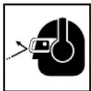
Notify the transporting company that a package contains a lithium-ion battery, inform the company of its power output and follow the instructions of the transportation company when arranging transport.
- Lithium-ion batteries that exceed a power output of 100 Wh are considered to be in the freight classification of Dangerous Goods and will require special application procedures.
- For transportation abroad, you must comply with international law and the rules and regulations of the destination country.
- If the BSL36B18 is installed in the power tool, the power output will exceed 100 Wh and the unit will be classified as Dangerous Goods for freight classification.
WARNING
If an electrically conductive foreign object enters fight
terminals of the lithium ion battery, a short-circuit may occur resulting in the risk of fire. Please observe the following matters when storing the battery.
- Do not place electrically conductive cuttings, nails, steel wire, copper wire or other wire in the storage case.
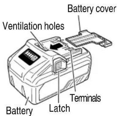
Either install the battery in the power tool or store by securely pressing into the battery cover until the ventilation holes are concealed to prevent short-circuits (See Fig. 3).
SAVE THESE INSTRUCTIONS
AND
MAKE THEM AVAILABLE TO OTHER USERS
AND
OWNERS OF THIS TOOL!
FUNCTIONAL DESCRIPTION
NOTE
The information contained in this Instruction Manual is designed to assist you in the safe operation and maintenance of the power tool.
NEVER operate, or attempt any maintenance on the tool unless you have first read and understood all safety instructions contained in this manual.
Some illustrations in this Instruction Manual may show details or attachments that differ from those on your own power tool.
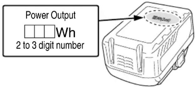
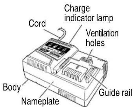
NAME OF PARTS
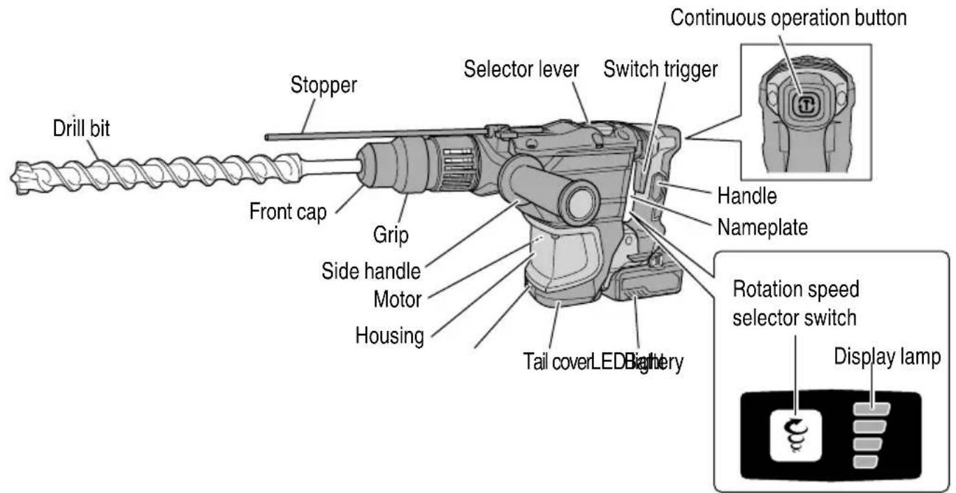
Fig. 2
- Battery 3. Battery Charger
SPECIFICATIONS
1. Cordless Rotary Hammer
| Model DH3640DA | ||
| Motor DC motor | ||
| Capacity Drill bit: 1-9/16" (40 mm) | Core bit: 4-1/8" (105 mm) | |
| No-load speed 250-500 /min | ||
| Full-load impact rate 1,400-2,800 /min | ||
| Battery* | Model BSL36B18 | |
| Type Li-ion battery | ||
| Voltage DC 36 V / 18 V | ||
| Weight 16.2 lbs (7.4 kg) (BSL36B18 attached) | ||
- Existing batteries (BSL3660/3626/3620, BSL18xx and BSL14xx series, etc.) cannot be used with this tool.
2. Battery Charger
| Model | UC18YSL3 |
| Input power source | Single phase: AC 120 V 60 Hz |
| Charging time (At a temperature of 68°F (20°C)) | BSL36B18 : Approx. 52 min |
| Charging voltage | DC 14.4–18 V |
| Charging current | DC 8.0 A |
| Weight | 1.3 lbs. (0.6 kg) |
ASSEMBLY AND OPERATION
APPLICATIONS
Rotation and hammering function
Drilling anchor holes
Drilling holes in concrete
Hammering only function
Crushing concrete, chipping, digging, and squaring
(Some applications need optional accessories)
REMOVAL AND INSTALLATION METHOD OF BATTERY
- Battery installation
Align the battery with the groove in tool handle and slip it into place.
Always insert it all the way until it locks in place with a little click, If not, it may accidentally fall out of the tool, causing injury to you or someone around you (Fig. 5).
- Battery removal
Lower the stopper lever to detach the lock. Press the latches on both sides and slide out the battery (Fig. 6).
CAUTION
Never short-circuit the battery.
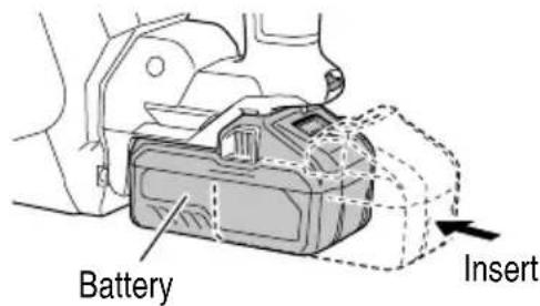
Fig. 5
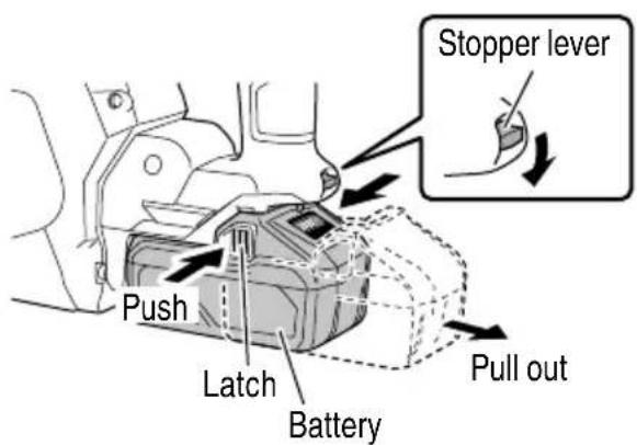
Fig. 6
CHARGING METHOD
NOTE
Before plugging into the receptacle, make sure the following points.
The power source voltage is stated on the nameplate.
The cord is not damaged.

WARNING
Do not charge at voltage higher than indicated on the nameplate.
If charged at voltage higher than indicated on the nameplate, the charger will burn up.
- Connect the charger's power cord to a receptacle. When the power cord is connected, the Charge indicator lamp will blink in red. (At 1-second intervals)


WARNING
Do not use the electrical cord if damaged. Have immediately.
- Insert the battery to the battery charger.
Insert the battery into the battery charger as shown in Fig. 7.
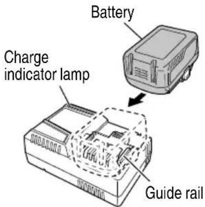
Fig. 7
- Charging
When inserting a battery in the charger, the charge indicator lamp will blink in blue.
When the battery becomes fully recharged, the charge indicator lamp will light up in green. (See Table 2)
(1) Charge indicator lamp indication
The indications of the charge indicator lamp will be as shown in Table 2, according to the condition of the battery charger or the battery.
Table 2
| Indications of the charge indicator lamp | ||||
| Charge indicator lamp (RED / BLUE / GREEN / PURPLE) | Before charging | Blinks (RED) | Lights for 0.5 seconds. Does not light for 0.5 seconds. (off for 0.5 seconds) | Plugged into power source |
| While charging | Blinks (BLUE) | Lights for 0.5 seconds. Does not light for 1 second. (off for 1 second) | Battery capacity at less than 50% | |
| Blinks (BLUE) | Lights for 1 second. Does not light for 0.5 seconds. (off for 0.5 seconds) | Battery capacity at less than 80% | ||
| Lights (BLUE) | Lights continuously | Battery capacity at more than 80% | ||
| Charging complete | Lights (GREEN) | Lights continuously (Continuous buzzer sound: about 6 seconds) | ||
| Overheat standby | Blinks (RED) | Lights for 0.3 seconds. Does not light for 0.3 seconds. (off for 0.3 seconds) | Battery overheated. Unable to charge. (Charging will commence when battery cools) | |
| Charging impossible | Flickers (PURPLE) | Lights for 0.1 seconds. Does not light for 0.1 seconds. (off for 0.1 seconds) (Intermittent buzzer sound: about 2 seconds) | Malfunction in the battery or the charger | |
(2) Regarding the temperature of the rechargeable battery.
The temperatures for rechargeable batteries are as shown in the Table 3, and batteries that have become hot should be cooled for a while before being recharged.
Table 3
| Rechargeable batteries | Temperatures at which the battery can be recharged |
| BSL36B18 | 32°F-122°F (0°C-50°C) |
(3) Regarding recharging time (At 68^ (20^) )
Table 4 Charging time
| Charger Battery | UC18YSL3 |
| BSL36B18 Approx. 52 min | |
NOTE
The recharging time may vary according to the ambient temperature.
- Disconnect battery charger from the receptacle.
CAUTION
Do not pull the plug out of the receptacle by pulling on the cord.
Make sure to grasp the plug when removing from receptacle to avoid damaging cord.
- Remove the battery from the battery charger.
Supporting the battery charger with hand, pull out the battery from the battery charger.
NOTE
Be sure to pull out the battery from the battery charger after use, and then keep it.
Regarding electric discharge in case of new batteries, etc.
As the internal chemical substance of new batteries and batteries that have not been used for an extended period is not activated, the electric discharge might be low when using them the first and second time. This is a temporary phenomenon, and normal time required for recharging will be restored by recharging the batteries 2-3 times.
How to make the batteries perform longer
(1) Recharge the batteries before they become completely exhausted.
When you feel that the power of the tool becomes weaker, stop using the tool and recharge its battery. If you continue to use the tool and exhaust the electric current, the battery may be damaged and its life will become shorter.
(2) Avoid recharging at high temperatures.
A rechargeable battery will be hot immediately after use. If such a battery is recharged immediately after use, its internal chemical substance will deteriorate, and the battery life will be shortened. Leave the battery and recharge it after it has cooled for a while.
CAUTION
- When the battery charger has been continuously used, the battery charger will be heated, thus constituting the cause of the failures. Once the charging has been completed, give 15 rest until the next charging.
- If the battery is charged while it is heated because it has been left for a long time in a location subject to direct sunlight or because the battery has just been used, the charge indicator lamp of UC18YSL3 charger lights for 0.3 seconds, does not light for 0.3 seconds (off for 0.3 seconds). In such a case, first let the battery cool, then start charging.
- When the charge indicator lamp flickers (at 0.2-second intervals), check for and take out any foreign objects in the charger's battery installation hole. If there are no foreign objects, it is probable that the battery or charger is malfunctioning. Take it to your authorized Service Center.
HOW TO RECHARGE USB DEVICE
When an unexpected problem occurs, the data in a USB device connected to this product may be corrupted or lost. Always make sure to back up any data contained in USB device prior to use with this product.
Please be aware that our company accepts absolutely no responsibility for any data stored in a USB device that is corrupted or lost, nor for any damage that may occur to a connected device.
WARNING
Prior to use, check the connecting USB cable for any defect or damage. Using a defective or damaged USB cable can cause smoke emission or ignition.
When the product is not being used, cover the USB port with the rubber cover.
Buildup of dust etc. in the USB port can cause smoke emission or ignition.
NOTE
The time required for charging will be longer when a USB device and battery are being simultaneously charged.
There may be an occasional pause during USB recharging.
When a USB device is not being charged, turn the USB power switch OFF and remove the USB device from the charger.
mints to do so may not only reduce the battery life of a USB device, but may also result in unexpected accidents.
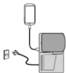
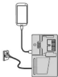
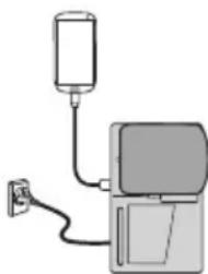
(1) Select a charging method
Depending on the charge method selected, either the battery is inserted into the charger or the power cord is plugged into an outlet.
O Charging a USB device by battery (Fig. 8-a)
O Charging a USB device from a electrical outlet (Fig. 8-b)
O Charging a USB device and battery from a electrical outlet (Fig. 8-c)
a
b
C
Fig. 8
(2) Turn the USB power switch ON (Fig. 9) When you turn the USB power switch ON, the USB power indicator lamp will light up.
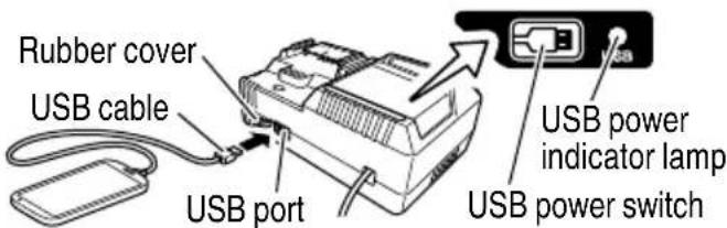
Fig. 9
(3) Connect the USB cable. (Fig. 9) Pull back the rubber cover and firmly plug commercially available USB cable (appropriate to the device being charged) into the USB port.
- When the power cord is not plugged into an outlet and the battery runs out of power, power output will stop and the USB power indicator lamp will shut off.
- When the USB power indicator lamp goes out, change the battery or plug the power cord into an electrical outlet.
(4) When charging is completed
The USB power indicator lamp will not go out when a USB device has been completely charged.
To verify charge status, check the USB device.
Turn the USB power switch OFF and unplug the power cord from the electrical outlet. (Fig. 9)
- Remove the battery from the charger and place the rubber cover over the USB port.
BEFOREUSE
Check the work area to make sure that it is clear of debris and clutter.
Clear the area of unnecessary personnel. Ensure that lighting and ventilation is adequate.
PRIOR TO OPERATION
CAUTION
To prevent accidents, make sure to turn the switch off and disconnect the battery when the drill bits and other various parts are installed (Fig. 13)
or removed. The power switch should also be turned off during a work break and after work.
- Power switch
Ensure that the power switch is in the OFF position. If the battery is inserted while the power switch is in the ON position, the power tool will start operating immediately, which could cause a serious accident.
-
Confirming condition of the environment: Confirm that the work site is placed under appropriate conditions conforming to prescribed precautions.
-
Installing the Side Handle
(1) Turn the side handle to dismantle. (Fig. 10)
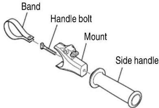
Fig. 10
(2) Place the band over the band attachment area and fit the band's two holes onto the "T" portion of the handle bolt. (Fig. 11, 12)
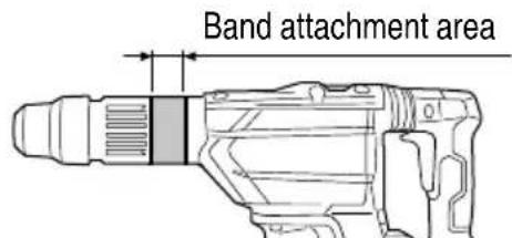
Fig. 11
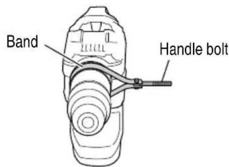
Fig. 12
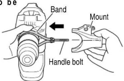
Fig. 13
(4) Adjusting the band to a position that is suitable for the task, turn the side handle to fasten the band. Make sure that the band is securely fastened. (Fig. 14)
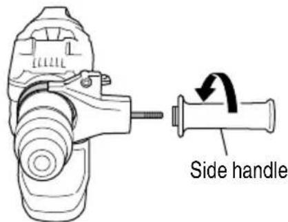
Fig. 14
- How to install tool
CAUTION
For tools such as a drill bit and a bull point, use only metabo HPT genuine parts.
(1) Clean, then smear the tool shank with the grease provided in the tube.
(2) To attach the tool (SDS max shank), insert it into the hole until it contacts the innermost end of the hole as illustrated in Fig. 15.
Turn the tool while gently pressing it in, and the groove of the tool will catch, allowing the tool to enter deeply until it is inserted all the way.
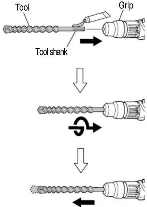
Fig. 15
(3) Pull the tool to make sure it is locked completely.
(4) To remove the tool, fully pull the grip in the direction of the arrow and pull out the tool (Fig. 16).
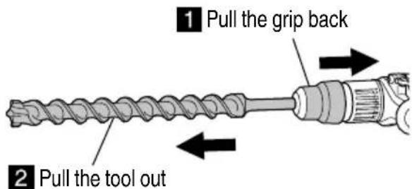
Fig. 16
- Regulating the number of rotations and hammering (Fig. 17)
This Rotary Hammer is equipped with a built-in electronic control circuit that can adjust and regulate the number of rotations and times of hammering. This Rotary Hammer can be used by adjusting the rotation speed selector switch, depending upon the contents of operation, such as boring holes into fragile materials, chipping, centering, etc.
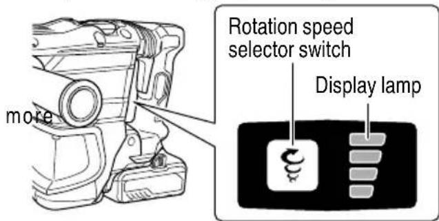
Fig. 17
Pressing the rotation speed selector switch switches rotation speeds as shown in Table 5.
Table 5
| Display lamp sequence | ||||
| No-load speed (/min) | 250 | 340 | 420 | 500 |
| Full-load impact rate (/min) | 1,400 | 1,900 | 2,350 | 2,800 |
NOTE
- Rotation speed cannot be adjusted until a battery is installed to the power tool and the switch has been triggered once.
The rotation speed cannot be changed by pressing the rotation speed selector switch while the motor is rotating. To change speeds, switch off the tool first.
6. About the protection function
This product features functions that are designed to protect the tool itself as well as the battery. While the switch is pulled, if any of the safeguard functions are triggered during operation, the display lamp will blink as described in Table 6. When any of the safeguard functions are triggered, immediately remove your fi nger from the switch and follow the instructions described under corrective action.
Table 6
| Display lamp fl ashing | Cause Solution | |
| Flash | Internal temperature has risen beyond the unit's specified temperature. (Temperature increase protection function) | Turn off the unit and allow it to cool down for about 15 to 30 minutes. When the temperature goes down, press the rotation speed selector switch to recover. |
| Flash | Excessive pressure applied to the tool has resulted in an overload. (Overload protection function) | Press the rotation speed selector switch to recover. Try to avoid tasks that will apply excess pressure to the unit. |
| Flash | Sensor signal read error. (Control monitoring function) | Press the rotation speed selector switch to recover. Repair may be required if this error continuously occurs. |
NOTE
Repair may be required if the display lamp continues to flash after taking all necessary steps to correct the problem. If the problem persists, please arrange for repairs.
7. About remaining battery indicator
You can check the battery's remaining capacity by pressing the remaining battery indicator switch to light the indicator lamp. (Fig. 18, Table 7) The indicator will shut off approximately 3 seconds after the remaining battery indicator switch is pressed.
It is best to use the remaining battery indicator as a guide since there are slight differences such as ambient temperature and the condition of the battery. Also, the remaining battery indicator may vary from those equipped to a tool or charger.
Table 7
| State of lamp | Battery Remaining Power |
| Lights; The battery remaining power is over 75% | |
| Lights; The battery remaining power is 50%-75%. | |
| Lights; The battery remaining power is 25%-50%. | |
| Lights; The battery remaining power is less than 25% | |
| Blinks; The battery remaining power is nearly empty. Recharge the battery soonest possible | |
| Blinks; Output suspended due to high temperature. Remove the battery from the tool and allow it to fully cool down. | |
| Blinks; Output suspended due to failure or malfunction. The problem may be the battery so please contact your dealer. |
As the remaining battery indicator shows somewhat differently depending on ambient temperature and battery characteristics, read it as a reference.
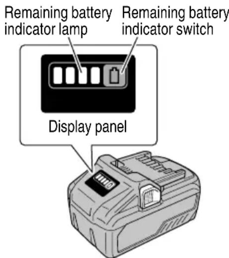
Fig. 18
NOTE
Do not give a strong shock to the display panel or break it. It may lead to a trouble.
- How to use the LED light
While the switch is pulled, the LED light will automatically light up the tip portion of the tool. (Fig. 19)
The LED light will automatically turn off 10 seconds after the switch is released.
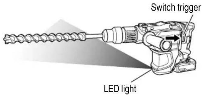
Fig. 19
CAUTION
- Do not expose directly your eye to the light by looking into the light.
If your eye is continuously exposed to the light, your eye will be hurt.
- Wipe off any dirt or grime attached to the lens of the LED light with a soft cloth, being careful not to scratch the lens.
Scratches on the lens of the LED light can result in decreased brightness.
HOW TO USE
CAUTION
To prevent accidents, make sure switch off and disconnect the battery when the drill bits and other various parts are installed or removed. The power switch should also be turned off during a work break and after work. (1)
- How to drill holes (Fig. 20)
(1) Pull the switch trigger after applying the drill bit tip to the drilling position.
(2) It is unnecessary to forcibly press the Rotary Hammer main body. It is sufficient to slightly press the rotary hammer to an extent that clips are freely discharged.
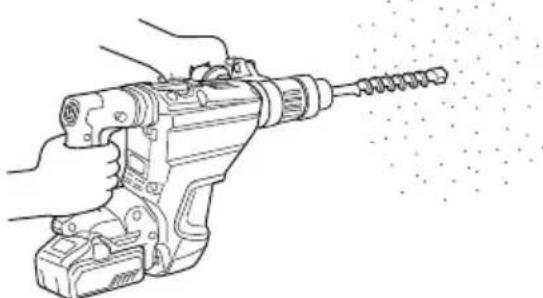
Fig. 20
CAUTION
Although this machine is equipped with a slip clutch, if the drill bit becomes bound in concrete or other material, the resultant stoppage of the drill bit could cause the machine body to turn in reaction. Ensure that the main handle and side handle are gripped firmly during operation.
- How to chisel or demolish (Fig. 21)
By applying the tool tip to the chiseling or demolishing position, operate the rotary hammer by utilizing its own weight. Forcible pressing or thrusting is unnecessary.
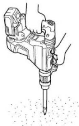
Fig. 21
- When drilling at "rotation + hammering"
CAUTION
If you switch the selector lever during motor rotation, the tool can start to rotate abruptly, resulting in unexpected accidents. Be sure to switch the selector lever when the motor is at a complete stop.
(1) Switching to "rotation + hammering"
(a) Turn the selector lever.
(b) Align of the selector lever and IT of the crank cover as illustrated in Fig. 22.
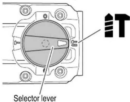
Fig. 22
- When crushing and chipping at "hammering":
CAUTION
If the selector lever is switched during motor rotation, the tool can start to rotate abruptly, resulting in unexpected accidents. Make sure to switch the selector lever when the motor is at a complete stop.
If the bull point or cold chisel is position of "rotation + hammering", the tool can start to rotate, resulting in unexpected accidents. Make sure that they are used at the positon of "hammering".
(1) Switching to "hammering"
(a) Turn the selector lever.
(b) Align of the selector lever and T of the crank cover as illustrated in Fig. 23.
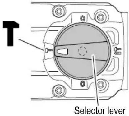
Fig. 23
(2) When fi xing working positions of tools such as cold chisel, etc..
(a) Turn the selector lever.
Align of the selector lever and of the crank cover as illustrated in Fig. 24.
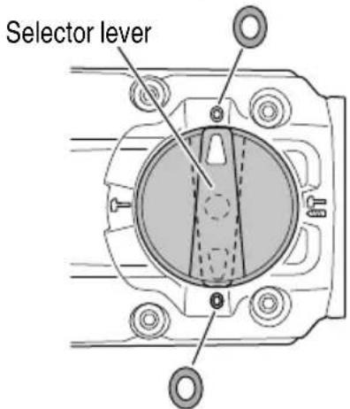
Fig. 24
(b) Turn the Grip or the Tool as illustrated in Fig and fix the tool to the desired working direction.
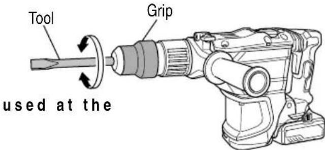
Fig. 25
(c) Switch the selector lever to "hammering" according to the procedures mentioned in the above item (1) and secure the position of the tool.
- Install the stopper (Fig. 26)
(1) Loosen the wing bolt, and insert the stopper into the mounting hole on the side handle.
(2) Adjust the stopper position according to the depth of the hole and tighten the wing bolt securely.
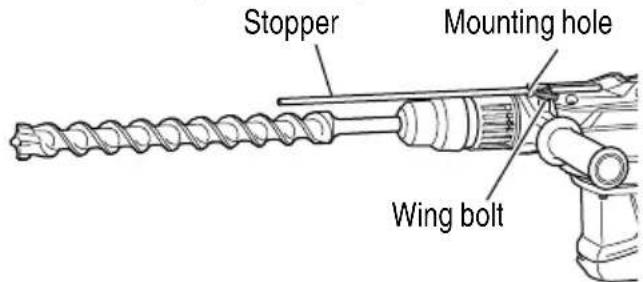
Fig. 26
- Warming up (Fig. 27)
The grease lubrication system in this unit may require warming up in cold regions.
Position the end of the bit so makes contact with the concrete, turn on the switch and perform the warming up operation. Make sure that a hitting sound is produced and then use the unit.
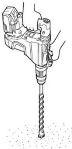
Fig. 27
CAUTION
When the warming up operation is performed, hold the side handle and the main body securely with both hands to maintain a secure grip and be careful not to twist your body by the jammed drill bit.
7. Using the Continuous operation button
When operating this machine in "T hammering" mode, you can set it to remain ON after the switch is released by pressing the Continuous operation button.
CAUTION
Never allow magnets (or similar magnetic devices) to be adjacent to this product has a magnetic sensor inside. Doing so will cause a failure or risk of injury by malfunction.
| Selector lever Operation | |
| “hammering” | Press the Continuous operation button with the switch trigger pulled back (Blue LED will light up) |
| [To cancel Continuous operation] Press the Continuous operation button | |
| “rotation + hammering” | Continuous operation button cannot be used for this mode |
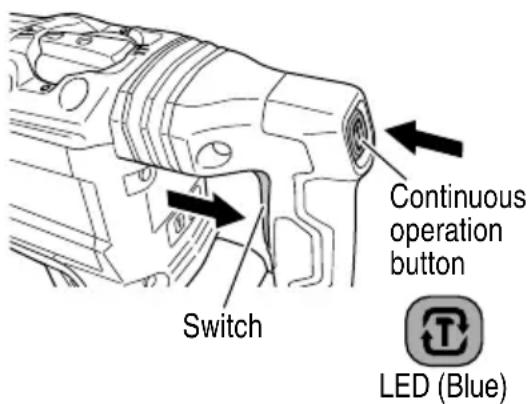
Fig. 28
USING DRILL CHUCK, CHUCK ADAPTOR
Note that this machine can be used at "rotation only" if separately sold parts such as drill chuck and chuck adaptor are attached. Use it with the selector lever positioned at "rotation + hammering".
WARNING
During operation, be sure to grip the handle and the side handle firmly to prevent your body from swaying.
CAUTION
To prevent accidents, make sure switch off and pull out the battery.
(1) Switching to "rotation + hammering"
For switching to "rotation + hammering", follow the same procedures mentioned in [3. When drilling at "rotation + hammering"] in Page 16.
(2) Attaching chuck adaptor to drill chuck (Fig. 29)
(a) Attach the chuck adaptor to the drill chuck.
I b) They SDS are anach of the chuck adaptor is equivalent to the drill bit. Therefore, follow the same procedure as [4. How to install tool] in Page 14 for attaching and detaching.
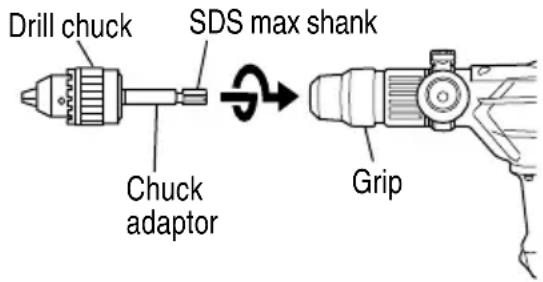
Fig. 29
(3) Drilling
(a) Even if you apply more-than-required pressure to the machine body, drilling can never be performed as quickly as you expect. Applying more force or pressure to the machine body than what is needed, on the contrary, damages the drill tip, resulting in the declined working efficiency and shortened life of this machine.
(b) A drill can snap sometimes when drilling is almost finished. It is important to relax your thrusting pressure when drilling is nearing the end.
HOW TO USE THE CORE BIT
When boring penetrating large hole use the core bit. At that time use with the center pin and the core bit shank provided as optional accessories.
1. Mounting
CAUTION
To prevent accidents, make sure switch off and pull out the battery.
(1) Mount the core bit to the core bit shank. (Fig. 30) Lubricate the thread of the core bit shank to facilitate disassembly.
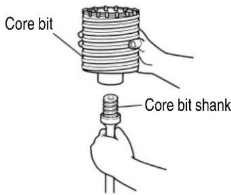
Fig. 30
(2) Mount the core bit shank to the Rotary Hammer. (Fig. 31)
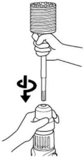
Fig. 31
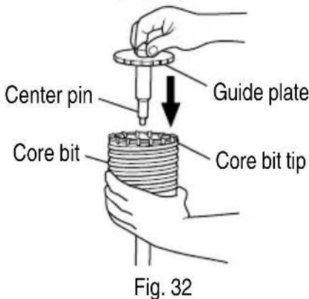
(3) Insert the center pin into the guide plate until it stops.
(4) Engage the guide plate with the core bit, and turn the guide plate to left or right so that it does not fall even if it faces downward. (Fig. 32)
- How to bore (Fig. 33)
(1) Install the battery.
(2) A spring is installed in the center pin. Push it lightly to the wall or the floor straight. Connect all over the surface of the core bit tip and start operating.
(3) When boring about 3 / 16^ (5 mm) in depth the position of the hole will establish. Bore after that removing the center pin and the guide plate from core bit.
(4) Application of excessive force will not only expedite the work, but will deteriorate the tip edge of the drill bit, resulting in reduced service life of the rotary hammer.
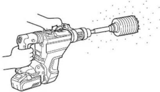
Fig. 33
CAUTION
When removing the center pin and the guide plate, turn OFF the switch and pull out the battery.
- Dismounting (Fig. 34)
Remove the core bit shank from the rotary hammer and strike the head of the core bit shank strongly two or three times with a manual hammer holding the core bit, then the thread becomes loose and the core bit can be removed.
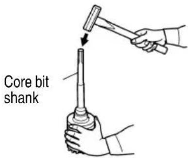
Fig. 34
REACTIVE FORCE CONTROL
This product is equipped with a Reactive Force Control (RFC) feature that reduces jerking of the tool body.
If the tool bit is suddenly overburdened, any jerking of the tool body is reduced by activation of the slip clutch or by stopping of the motor by the sensor built into the tool body. If the motor is stopped because of overburdening detection by the controller, the Display lamp will blink while the switch is pulled.
In addition, the lamp will continue blinking for approximately three seconds after the switch is released.
The motor will remain stopped while the lamp is blinking. (Fig. 35)
Because the RFC feature may not activate or its performance may be insuffcient depending on the working environment and conditions, be careful not to suddenly overburden the tool bit and hold power tool firmly while operating.
Possible causes of sudden overburdening
① Tool bit biting into material
② Impact against nails, metal or other hard objects
③ Tasks involving prying or any excess application of pressure, etc.
Also, other causes include any combination of the aforementioned.
- When the reactive force control (RFC) is triggered When the RFC is triggered and the motor stops, turn off the tool's switch and remove the cause of the overburdening before continuing operation.
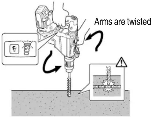
Fig. 35
OPERATIONAL CAUTIONS
Resting the unit after continuous work
(1) The power tool is equipped with a temperature protection circuit to protect the motor.
Continuous work may cause the temperature of the unit to rise, activating the temperature protection circuit and automatically stopping operation.
If this happens, allow the power tool to cool before resuming use.
(2) After use for continuous work, rest the unit for 15 minutes or so when replacing the battery. The temperature of the motor, switch, etc., will rise if the work is started again immediately after battery replacement, eventually resulting in burnout.
MAINTENANCE AND INSPECTION
WARNING
Be sure to turned off the switch and remove the battery before maintenance and inspection.
- Inspecting the tool bits
Since use of a dull tool will cause motor malfunctioning and degraded efficiency, replace the tool bit with a new one or resharpening without delay when abrasion is noted.
- Inspecting the screws
Regularly inspect all screws and ensure that they are properly tightened. Should any of the screws be loose, retighten them immediately.
WARNING
Using this Rotary Hammer with loosen screws is extremely dangerous.
- Maintenance of the motor
The motor unit is the very "heart" of the power tool. Exercise due care to ensure the motor does not become damaged and/or wet with oil or water.
- Grease replacement
This Rotary Hammer is of full air-tight construction to protect against dust.
Therefore, this Rotary Hammer can be used without lubrication for long periods. Refer to the following for grease replacement.
Grease Replacement Period
After purchase, replace grease after every 6 months of usage. Ask for grease replacement at the nearest authorized Service Center.
- Inspection of terminals (tool and battery) Check to make sure that swarf and dust have not collected on the terminals. On occasion check prior, during and after operation.

CAUTION
Remove any swarf or dust which may have collected on the terminals.
Failure to do so may result in malfunction.
-
Cleaning on the outsider When the power tool is stained, wipe with a soft dry cloth or a cloth moistened with soapy water. Do not use chloric solvents, gasoline or paint thinner, for they melt plastics.
-
Cleaning the battery installation compartment and the battery After drilling concrete, if concrete dust has accumulated on the battery installation compartment and the battery, clean off the accumulated concrete dust with an air gun or a dry cloth before using the tool. (Fig. 36) Also, after cleaning, ensure that the battery can be installed and removed smoothly from the tool.

CAUTION
Using the tool when the battery is covered with concrete dust may lead to accidents such as the battery falling during use. Furthermore, such use may cause a malfunction or contact failure between the battery and the terminals.
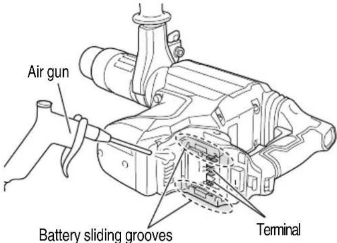
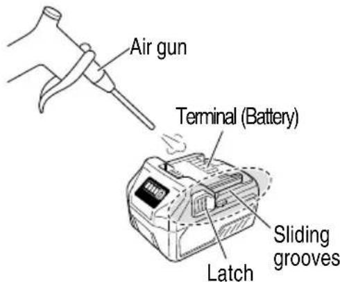
Fig. 36
- Disposal of the exhausted battery

WARNING
Do not dispose of the exhausted battery. The battery must explode if it is incinerated. The product that you have purchased contains a rechargeable battery. The battery is recyclable. At the end of its useful life, under various state and local laws, it may be illegal to dispose of this battery into the municipal waste stream. Check with your local solid waste officials for details in your area for recycling options or proper disposal.
- Storage Storing in a place below 104^ (40^) and out of the reach of children.
NOTE
Storing lithium-ion batteries
Make sure the lithium-ion batteries have been fully charged before storing them.
Prolonged storage (3 months or more) of batteries with
a low charge may result in performance deterioration, signifi cantly reducing battery usage time or rendering the batteries incapable of holding a charge.
However, signifi cantly reduced battery usage time may be recovered by repeatedly charging and using the batteries two to five times.
If the battery usage time is extremely short despite repeated charging and use, consider the batteries dead and purchase new batteries.
- Service and repairs
All quality power tools will eventually require servicing or replacement of parts because of wear from normal use. To assure that only authorized replacement parts will be used, all service and repairs must be performed by a metabo HPT AUTHORIZED SERVICE CENTER, ONLY.
CAUTION
In the operation and maintenance of power tools, the safety regulations and standards prescribed in each country must be observed.
Important notice on the batteries for the metabo HPT cordless power tools
Please always use one of our designated genuine batteries. We cannot guarantee the safety and performance of our cordless power tool when used with batteries other than these designated by us, or when the battery is disassembled and modified (such as disassembly and replacement of cells or other internal parts).
TROUBLESHOOTING GUIDE
WARNING
- To avoid injury from an accidental start, turn the switch OFF and remove the plug from the power source or remove the battery from the main body before making any adjustments.
-
All electrical or mechanical repairs should be done only by qualified service technicians. Contact metabo HPT Authorized Service Center.
-
Power tool
| Symptom Possible | cause Remedy | ||
| Tool doesn't run No remaining | battery power Charge the battery. | ||
| Battery isn't securely attached. Push in the battery until a click is heard. | |||
| Concrete dust has accumulated on the terminals of the battery installation compartment as well as on the battery sliding grooves. | Clean off the accumulated concrete dust with a dry cloth. | ||
| The battery was attached while the switch trigger was ON. | Attach the battery when the switch trigger is OFF. | ||
| Tool suddenly stopped Tool | was overburdened Remove the cause of the overburdening.See "Reactive force control". | ||
| Reactive force control was activated | |||
| Battery or tool overheated | Allow the tool and battery to thoroughly cool. | ||
| Tool bits -can't be attached -fall off | The shape of the attachment portion doesn't match | For the SDS-max shank type, use a bit with a diameter that is within the designated range. | |
| Holes can't be smoothly drilled. | The drill is worn | Replace with a new drill. | |
| Battery cannot be installed | Attempting to install a battery other than that specified for the tool. | Please install a multi volt type battery. | |
- Charger
| Symptom Possible | cause Remedy | |
| The charge indicator lamp is rapidly flickers purple, and battery charging doesn't begin. | The battery is not inserted all the way. | Insert the battery firmly. |
| There is foreign matter in the battery terminal or where the battery is attached. | Remove the foreign matter. | |
| The charge indicator lamp blinks red, and battery charging doesn't begin. | The battery is not inserted all the way. | Insert the battery firmly. |
| The battery is overheated. | If left alone, the battery will automatically begin charging if its temperature decreases, but this may reduce battery life. It is recommended that the battery be cooled in a well-ventilated location away from direct sunlight before charging it. | |
| Battery usage time is short even though the battery is fully charged. | The battery's life is depleted. Replace the battery with a new one. | |
| The battery takes a long time to charge. | The temperature of the battery, the charger, or the surrounding environment is extremely low. | Charge the battery indoors or in another warmer environment. |
| The charger's vents are blocked, causing its internal components to overheat. | Avoid blocking the vents. | |
| The cooling fan is not running. Contact a metabo HPT Authorized Service Center for repairs. | ||
| The USB power lamp has switched off and the USB device has stopped charging. | The battery's capacity has become low. Replace the battery with one that has capacity remaining. | |
| Plug the charger's power plug into an electric socket. | ||
| USB power lamp does not switch off even though the USB device has fi nished charging. | The USB power lamp lights up green to indicate that USB charging is possible. | This is not a malfunction. |
| It is unclear what the charging status of a USB device is, or whether its charging is complete. | The USB power lamp does not switch off even when charging is complete. | Examine the USB device that is charging to confi rm its charging status. |
| Charging of a USB device pauses midway. | The charger was plugged into an electrical socket while the USB device was being charged using the battery as the power source. | This is not a malfunction. The charger pauses USB charging for about 5 seconds when it is diff erentiating between power sources. |
| A battery was inserted into the charger while the USB device was being charged using a power socket as the power source. | ||
| Charging of the USB device pauses midway when the battery and the USB device are being charged at the same time. | The battery has become fully charged. This is not a malfunction. The charger pauses USB charging for about 5 seconds while it checks whether the battery has successfully completed charging. | |
| Charging of the USB device doesn't start when the battery and the USB device are being charged at the same time. | The remaining battery capacity is extremely low. | This is not a malfunction. When the battery capacity reaches a certain level, USB charging automatically begins. |
ACCESSIONS
WARNING
ALWAYS use Only authorized metabo HPT replacement parts and accessories. Never use replacement parts or accessories which are not intended for use with this tool. Contact metabo HPT if you are not sure whether it is safe to use a particular replacement part or accessory with your tool.
The use of any other attachment or accessory can be dangerous and could cause injury or mechanical damage.
NOTE
Accessories are subject to change without any obligation on the part of the metabo HPT.
STANDARD ACCESSORIES
(1) Plastic Case (Code No. 380211)
(2) Side Handle (Code No. 380210)
(3) Mount Ass'y (Code No. 380209)
(4) Handle Bolt (Code No. 331247)
(5) Band (Code No. 380208)
(6) Stopper (Code No. 971786)
(7) Hammer Grease A (Code No. 981840)
OPTIONAL ACCESSORIES.....sold separately
For accessories in detail please call metabo HPT AT 1-800-59-TOOLS
- Through-hole drilling (Rotation + Hammering)
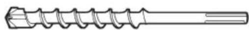
(1) Drill bit (SDS-max shank)
| External dia. Overall length Code No. | ||
| 5/8"(16 mm) | 13-3/8"(340 mm) | 313448 |
| 21-1/4"(540 mm) | 313456 | |
| 3/4"(19 mm) | 13-3/8"(340 mm) | 313449 |
| 21-1/4"(540 mm) | 313457 | |
| 7/8"(22 mm) | 12-5/8"(320 mm) | 313450 |
| 20-15/32"(520 mm) | 313458 | |
| 1"(25 mm) | 12-5/8"(320 mm) | 313451 |
| 20-15/32"(520 mm) | 313459 | |
| 1-1/8"(28 mm) | 14-9/16"(370 mm) | 313452 |
| 22-7/16"(570 mm) | 313460 | |
| 1-1/4"(32 mm) | 14-9/16"(370 mm) | 313453 |
| 22-7/16"(570 mm) | 313461 | |
| 1-1/2"(38 mm) | 14-9/16"(370 mm) | 313454 |
| 22-7/16"(570 mm) | 313462 | |
| 1-9/16"(40 mm) | 22-7/16"(570 mm) | 313463 |
- Anchor hole drilling (Rotation + Hammering)
- Large-dia. hole boring (Rotation + Hammering)
(Guide plate)
| External dia. of core bit | Code No. |
| 2" (50 mm) 95 | 0475 |
| 4-1/8" (105 mm) | 955169 |
(2) Core bit
| External dia. | Code No. |
| 2" (50 mm) 98 | 5380 |
| 4-1/8" (105 mm) | 955159 |
(1) Center pin
| Code No. |
| 955165 |
(3) Core bit shank (SDS max shank)
| Code No. |
| 313467 |
Including Guide Plate
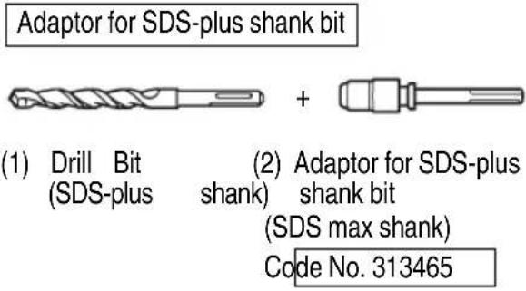
- Drilling holes...For drilling metals and wooden materials
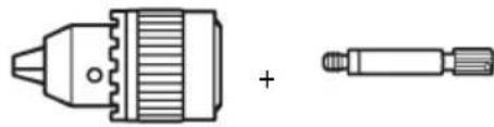
(1) 13mm drill chuck (13VLD-D)

(2) Chuck adaptor (SDS max shank) Code No. 313468
- Bolt plaching operation with Chemical Anchor 10. Surface Roughing (Hammering) (Rotation + Hammering)

+
(Standard socket on the market)
(1) Chemical Anchor Adaptor (SDS max shank)
| Square dimensions of the side of the socket installation | Code No. |
| 1/2" (12.7 mm) 313469 | |
| 3/4" (19.0 mm) 313470 |
- Crushing (Hammering)

(1) Bull point
| Overall length Code No. |
| 11" (280 mm) 313471 |
| 15-3/4" (400 mm) 313472 |
- Groove digging and edging (Hammering)

(1) Cold chisel
| Overall length Code No. |
| 11" (280 mm) 313473 |
| 15-3/4" (400 mm) 313474 |
- Asphalt cutting (Hammering)

(1) Cutter
| Overall length | Width | Code No. |
| 15-3/4" (400 mm) | 1-31/32" (50 mm) | 313475 |
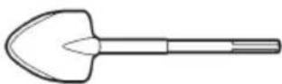
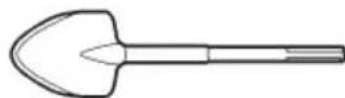
- Digging (Hammering)
(1) Scoop
Code No. 313476
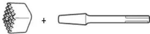
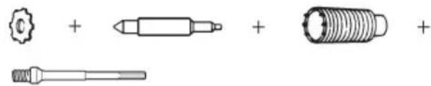
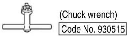
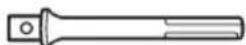
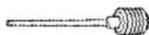
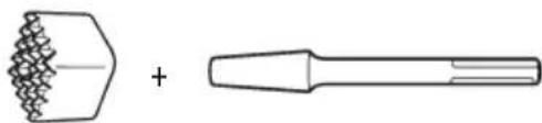
(1) Bushing Tool
Code No. 313477
(2) Shank
| Overall length | Code No. |
| 8-21/32" (220 mm) | 313479 |
- Tamping (Hammering)
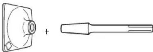
(1) Rammer
Code No. 313478
(2) Shank
| Overall length | Code No. |
| 8-21/32" (220 mm) | 313479 |
- Syringe (for chip removal)
Code No. 318085
- Hammer grease A
1.1 lbs (500 g) (in a can) Code No. 980927
0.15 lbs (70 g) (in a tube) Code No. 308471
0.07 lbs (30 g) (in a tube) Code No. 981840
- Battery (BSL36B18)
NOTE
Specifications are subject to change without any obligation on the part of the metabo HPT.
INFORMATIONS IMPORTANTES DE SECURITE
- Broyage (Percussion)

(1) Point de broyage
| Longueur totale No. | de code |
| 11" (280 mm) 3134 | 71 |
| 15-3/4" (400 mm) 313472 | |
- Puisage (Percussion)
(1) Scoop
No. de code 313476
- Degrossissage (Percussion)
(1) Boucharde
No. de code 313477
(2) Queue
| Longueur totale | No. de code |
| 8-21/32" (220 mm) | 313479 |
m = 311
MÉTODO DE EXTRACCIONE INSTALACION DE LA BATERIA
Some dust created by power sanding, sawing, grinding, drilling, and other construction activities contains chemicals known to the State of California to cause cancer, birth defects or other reproductive harm. Some examples of these chemicals are:
- Lead from lead-based paints,
- Crystalline silica from bricks and cement and other masonry products, and
- Arsenic and chromium from chemically-treated lumber.
Your risk from these exposures varies, depending on how often you do this type of work. To reduce your exposure to these chemicals: work in a well ventilated area, and work with approved safety equipment, such as those dust masks that are specially designed to filter out microscopic particles.
AVERTISSEMENT:
Please contact Koki Holdings America Ltd. at 1-800-59-TOOLS (toll free), or metabo HPT AUTHORIZED POWER TOOL SERVICE CENTER regarding COLLECTION.
Pour le RAMASSAGE,contacter Koki Holdings America Ltd. au 1-800-59-TOOLS (appel gratuite), ou UN SERVICE APRÉS-VENTE D'OUTILS ÉLECTRIQUE AGRÉE PAR metabo HPT.
Con respectfully a la RECOLECCION de baterias,pongase en contacto con Koki Holdings America Ltd. numero 1-800-59-TOOLS (llamada Gratis), o con metabo HPT AUTHORIZED POWER TOOL SERVICE CENTER.
Issued by
Koki Holdings Co., Ltd.
Shinagawa Intercity Tower A, 15-1, Konan 2-chome,
Minato-ku, Tokyo 108-6020, Japan
Distributed by
Koki Holdings America Ltd.
1111 Broadway Ave,
Braselton, Georgia, 30517
Koki Holdings America Ltd. Canadian Branch
3405 American Drive, Units 9-10
Mississauga, ON, L4V 1T6
306
Code No.C99748461 M
Printed in China

- SAFETY INSTRUCTIONS AND INSTRUCTION MANUAL
- WARNING
- INSTRUCTIONS DE SECURITE ET MODE D'EMPLOI
- AVERTISSEMENT
- IMPORTANT SAFETY INFORMATION
- MEANINGS OF SIGNAL WORDS
- SAFETY
- GENERAL POWER TOOL SAFETY WARNINGS
- -WARNING -
- SPECIFIC SAFETY RULES AND SYMBOLS
- Wear ear protectors.
- IMPORTANT SAFETY INSTRUCTIONS FOR BATTERY CHARGER
- READ ALL INSTRUCTIONS
- IMPORTANT SAFETY INSTRUCTIONS FOR USE OF THE BATTERY AND BATTERY CHARGER
- WARNING
- CAUTION ON LITHIUM-ION BATTERY
- CAUTION
- REGARDING LITHIUM-ION BATTERY TRANSPORTATION
- SAVE THESE INSTRUCTIONS
- AND
- MAKE THEM AVAILABLE TO OTHER USERS
- OWNERS OF THIS TOOL!
- FUNCTIONAL DESCRIPTION
- NOTE
- NAME OF PARTS
- SPECIFICATIONS
- Cordless Rotary Hammer
- Battery Charger
- ASSEMBLY AND OPERATION
- APPLICATIONS
- REMOVAL AND INSTALLATION METHOD OF BATTERY
- CHARGING METHOD
- Regarding electric discharge in case of new batteries, etc.
- How to make the batteries perform longer
- HOW TO RECHARGE USB DEVICE
- BEFOREUSE
- PRIOR TO OPERATION
- About the protection function
- About remaining battery indicator
- HOW TO USE
- Using the Continuous operation button
- USING DRILL CHUCK, CHUCK ADAPTOR
- Drilling
- HOW TO USE THE CORE BIT
- Mounting
- REACTIVE FORCE CONTROL
- OPERATIONAL CAUTIONS
- MAINTENANCE AND INSPECTION
- TROUBLESHOOTING GUIDE
- ACCESSIONS
- STANDARD ACCESSORIES
- OPTIONAL ACCESSORIES.....sold separately
- INFORMATIONS IMPORTANTES DE SECURITE
- MÉTODO DE EXTRACCIONE INSTALACION DE LA BATERIA
- AVERTISSEMENT:
- Koki Holdings Co., Ltd.
- Koki Holdings America Ltd.
- Koki Holdings America Ltd. Canadian Branch
Brand : HiKOKI
Model : DH3640DA
Category : Hammer