ECO 30 D - Fan Maico - Free user manual and instructions
Find the device manual for free ECO 30 D Maico in PDF.
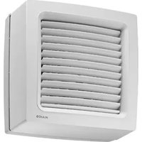
| Product type | Oscillating wall fan |
| Brand | Maico |
| Model | ECO 30 D |
| Fan blade diameter | 300 mm |
| Weight | 3.1 kg |
| Power supply | 230 V AC, 50 Hz |
| Rated current | 0.25 A |
| Power consumption | 37 W |
| Sound power level | 57 dB(A) |
| Protection class | IP 20 |
| Adjustable pivot angles | 55°, 70°, 90° (factory setting), 115° |
| Minimum mounting height | 2.30 m (between lower edge of guard and floor) |
| Permissible ambient temperature | +40 °C |
| Thermal protection | Automatic shutdown on overload, automatic restart after cooling |
| Variable speed | Yes (with optional speed controller) |
| Separate fan/oscillation control | Yes, via switch |
| Maintenance | No maintenance required; regular cleaning with a soft cloth, do not disassemble the guard |
| Bracket material | Steel |
| Mounting type | Wall-mounted (horizontal or vertical, not ceiling) |
| Electrical connection | Recessed (UP) or surface-mounted (AP) |
| Protection class | I (with PE conductor) |
| Spare parts available | Yes, list in the manual |
Frequently Asked Questions - ECO 30 D Maico
User questions about ECO 30 D Maico
0 question about this device. Answer the ones you know or ask your own.
Ask a new question about this device
Download the instructions for your Fan in PDF format for free! Find your manual ECO 30 D - Maico and take your electronic device back in hand. On this page are published all the documents necessary for the use of your device. ECO 30 D by Maico.
USER MANUAL ECO 30 D Maico
UK Mounting and Operating instructions Wall fan
natural_image
3D wireframe model of a fan or propeller with internal blades and mesh structure (no text or symbols)ECO 30 E
ECO 40 D

text_image
QR code image containing encoded data, no visible human-readable text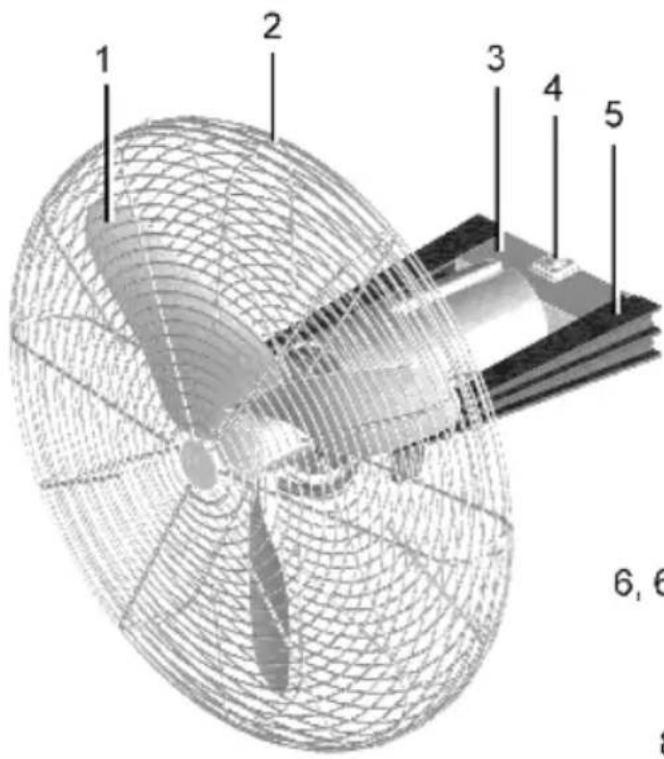
text_image
1 2 3 4 5 6, 6A
text_image
6, 6.1 7 8 9 10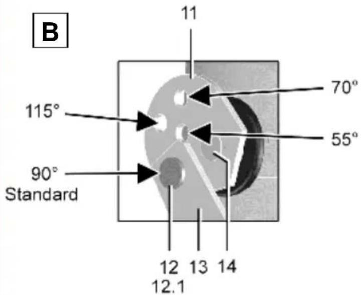
text_image
B 11 70° 55° 115° 90° Standard 12 13 14 12.1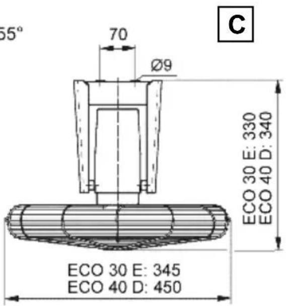
text_image
55° 70 Ø9 ECO 30 E: 330 ECO 40 D: 340 ECO 30 E: 345 ECO 40 D: 450 C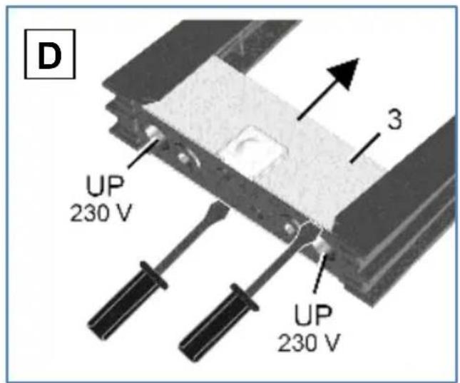
text_image
D UP 230 V 3 UP 230 V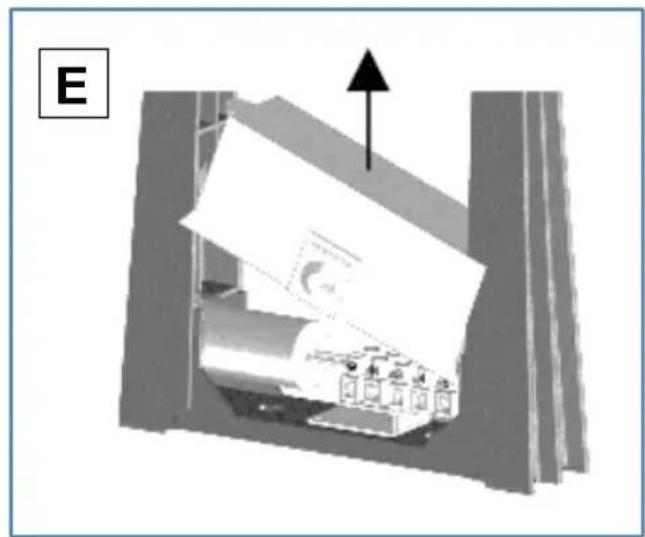
natural_image
Diagram of a mechanical device with an arrow indicating upward motion, no visible text or symbols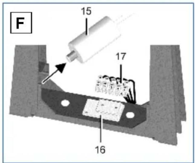
text_image
F 15 17 16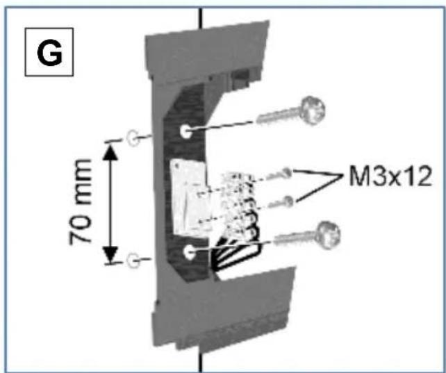
text_image
G 70 mm M3x12
text_image
H AP 230 V
natural_image
Technical diagram of a mechanical device with a 230 V power supply and a wire mesh structure (no text or symbols on the diagram itself)ECO 30 E, ECO 40 D
Please read the instructions carefully before mounting and using for the first time. Follow the instructions. Pass these instructions onto the owner for safekeeping.
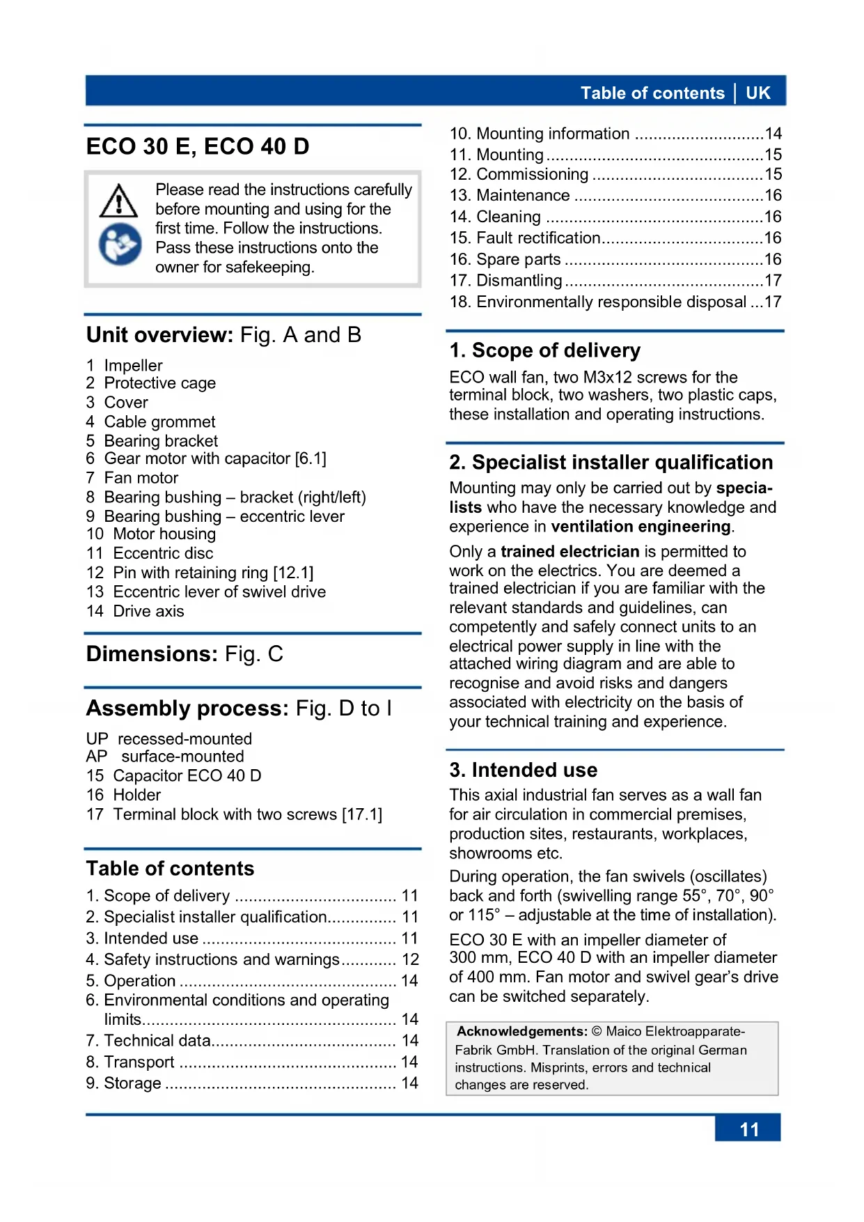
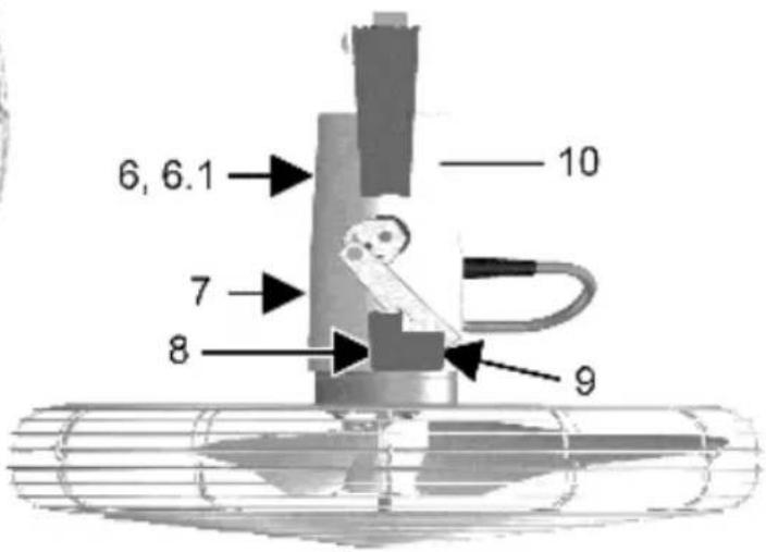
Unit overview: Fig. A and B
1 Impeller
2 Protective cage
3 Cover
4 Cable grommet
5 Bearing bracket
6 Gear motor with capacitor [6.1]
7 Fan motor
8 Bearing bushing – bracket (right/left)
9 Bearing bushing – eccentric lever
10 Motor housing
11 Eccentric disc
12 Pin with retaining ring [12.1]
13 Eccentric lever of swivel drive
14 Drive axis
Dimensions: Fig. C
Assembly process: Fig. D to I
UP recessed-mounted
AP surface-mounted
15 Capacitor ECO 40 D
16 Holder
17 Terminal block with two screws [17.1]
Table of contents
- Scope of delivery 11
- Specialist installer qualification.... 11
- Intended use 11
- Safety instructions and warnings...... 12
- Operation 14
- Environmental conditions and operating limits.... 14
- Technical data.... 14
- Transport 14
-
Storage 14
-
Mounting information .....14
- Mounting....15
- Commissioning .... 15
- Maintenance ....16
- Cleaning .... 16
- Fault rectification....16
- Spare parts .... 16
- Dismantling....17
- Environmentally responsible disposal ...17
1. Scope of delivery
ECO wall fan, two M3x12 screws for the terminal block, two washers, two plastic caps, these installation and operating instructions.
2. Specialist installer qualification
Mounting may only be carried out by specialists who have the necessary knowledge and experience in ventilation engineering.
Only a trained electrician is permitted to work on the electrics. You are deemed a trained electrician if you are familiar with the relevant standards and guidelines, can competently and safely connect units to an electrical power supply in line with the attached wiring diagram and are able to recognise and avoid risks and dangers associated with electricity on the basis of your technical training and experience.
3. Intended use
This axial industrial fan serves as a wall fan for air circulation in commercial premises, production sites, restaurants, workplaces, showrooms etc.
During operation, the fan swivels (oscillates) back and forth (swivelling range 55^ , 70^ , 90^ or 115^ – adjustable at the time of installation).
ECO 30 E with an impeller diameter of 300 mm, ECO 40 D with an impeller diameter of 400 mm. Fan motor and swivel gear's drive can be switched separately.
Acknowledgements: © Maico Elektroapparate-Fabrik GmbH. Translation of the original German instructions. Misprints, errors and technical changes are reserved.
UK | 3. Intended use
Operation is only permitted with:
- a fixed installation within buildings.
- installation on the wall with sufficient load-bearing capacity and sufficient room in ...the swivelling range. Installation position ...horizontal or vertical (swivel axis preferably ...horizontal). Do not install on the ceiling.
- Minimum installation height of 2.30 m: Lower edge of protective cage facing the floor.
Special version on request. Using the fan together with a frequency converter is only permissible after consultation with the manufacturer and a case-by-case examination.

4. Safety instructions and warnings
NOTICE: Shows a possible situation, which could cause damage to the product or its surroundings.
NOTICE:
Unit damage in case of incorrect transport if the fan unit slips out of the rotary axes. The fan unit is inserted in both bushings/rotary axes and is not secured. Therefore, hold the fan by the protective cage when removing it from the transport box and transport it.
The fan unit must not be used in the following situations under any circumstances.
Risk of combustion/fire from flammable materials, liquids or gases in the vicinity of the fan. Do not place any flammable materials, liquids or gases near the fan, which may ignite in the event of heat or sparks and catch fire.
Steam-saturated or greasy air or solid particles which may stick to the fan, can soil the fan and reduce the
efficiency. Never use fan to convey these substances.
Explosive gases and dusts may ignite and cause serious explosions or fire. Never use fan unit in an explosive atmosphere (risk of explosion).
Risk to health from chemicals or aggressive gases/vapours. Chemicals or aggressive gases/vapours may harm health, especially if they are distributed throughout the rooms by the fan. Never use fan to distribute chemicals or aggressive gases/vapours.
Risks in case of units installed on the ceiling. A ceiling installation of the wall fan is impermissible.
Observe all safety instructions!
Risks for children and people with reduced physical, sensory or mental capabilities or a lack of knowledge. Fan may only be installed, commissioned, cleaned and maintained by people who can safely recognise and avoid the risks associated with this work.
Danger of injury if foreign bodies are inserted into the unit. Do not insert any objects in the unit.
Risk of injury from rotating impeller. Hair, clothing, jewellery etc. may be pulled into the fan if you get too close to it. During operation always keep far enough away to prevent this from happening.
Health risk due to deposits on the unit (mould, bacteria, dust etc.) after the fan has not been used for a long time. Clean unit at regular intervals, especially after the fan has not been used for a long time.
A fan that is not mounted correctly may result in non-intended operation or impermissible operation. Do not remove protective cage. Operation only permissible with correctly installed protective cage.
Risk of injury and health risk in the event of changes or modifications or if components which are not permitted are used. The unit may only be operated with original components. Changes and modifications are not permitted and release the manufacturer from any guarantee obligations and liability, e.g. if the bearing bracket is drilled at a point which is not permitted.
Danger of injury when working at heights. Use appropriate climbing aids (ladders). Stability should be ensured, if necessary have the ladders steadied by a 2nd person. Ensure that you are standing securely and cannot lose your balance and that there is no one under the unit.
Danger of electric shock when operating a fan which is damaged or not fully mounted. Before taking off the cover [3], switch off all supply circuits (switch off mains fuse), secure against being accidentally switched back on and position a visible warning sign. Only operate the fan when it is completely installed. Do not commission a damaged unit.
Danger if the relevant regulations for electrical installations are not observed.
→ Before installing the electrics, shut down all supply circuits, deactivate the mains fuse and secure it so it cannot be switched back on. Attach a warning sign in a clearly visible place. Comply with the 5 safety regulations.
→ Be sure to observe the relevant regulations for electrical installation; e.g. DIN EN 50110-1, in Germany this is particularly VDE 0100, with the corresponding parts.
→ A mains isolation device with contact openings of at least 3 mm at each pole is mandatory.
→ Only connect unit to a permanently wired electrical installation with NYM-O / NYM-J, 3 x 1.5 mm ^2 cables.
→ The units may only be operated using the voltage and frequency shown on the rating plate.
→ The degree of protection stated on the rating plate is only guaranteed if installation is undertaken correctly and if the connection cable is correctly guided through the cable grommet. The grommet must tightly seal the cable sheathing.
→ With protection class I, connect the PE conductor and check the connection.
→ Check protective-conductor opening on housing.
→ Unit may also be energized even when at a standstill and may be switched on automatically by the thermal protection in the motor winding. Maintenance and fault finding only permissible when carried out by trained specialists.
Risk during transport due to heavy or falling loads. Observe applicable safety and accident prevention requirements. Do not stand under a suspended load. Check unit for transport damage.
Hearing damage caused by spending prolonged periods directly next to the unit while it is running. Depending on type, sound power levels of up to 65 dB(A). When planning, take into account sound insulation at the installation site when planning. If necessary, use hearing protection.
Risk of injury in case of incorrect mounting, if the fan falls down due to its inherent weight. The fan oscillates (swivels back and forth). Wall mounting only on walls with sufficient load-bearing capacity and with sufficiently dimensioned mounting material.
UK | 4. Safety instructions and warnings
Exercise caution when handling packaging materials.
→ Observe applicable safety and accident prevention requirements.
→ Store packaging material out of the reach of children (risk of suffocation).
5. Operation
Fan and swivel drive are switched on and off separately via a switch.
Special accessories with time-delayed switching or humidity function can be used.
In the event of thermal overload, the fan switches off. Wait until the motor has cooled down. Cool-down time can take up to 10 minutes. Unit switches back on automatically after cooling down.
6. Environmental conditions and operating limits
- Permitted ambient and airstream temperature + 40°C.
-
Information for operation with occasional temperatures below -20° on request.
-
Technical data
| Rated voltage | 230 VAC |
| Power frequency | 50 Hz |
| Power consumption | ECO 30 E: 37 WECO 40 D: 44 W |
| I_max | 0.25 A |
| Sound pressure level | ECO 30 E: 57 dB(AECO 40 D: 65 dB(A)) |
| Degree of protection IP | 20 |
| Weight | ECO 30 E: 3.1 kgECO 40 D: 4 kg |
For more technical data, rating plate. For dimensions Fig. C.
8. Transport
NOTICE:
Unit damage in case of incorrect transport if the fan unit slips out of the rotary axes.
The fan unit is inserted in both of the bushings/rotary axes and is not secured. Therefore, hold the fan by the protective cage when removing it from the transport box and transport it.
9. Storage
Store unit exclusively in a dry location (-20 to +50 °C).
10. Mounting information
- Installation only permissible on even, solid walls with sufficient load-bearing capacity (min. 200 kg/m ^3 ).
- Make sure there is sufficient space between the fan unit and the wall and ceiling.
- Can be installed in any position on the wall.
- Swivel axis should preferably be horizontal. For other swivel directions, feed the power cable through from the bottom if possible.
- Select installation site so that foreign bodies will not be accidentally drawn in. Observe installation height.
- Take the risk of draughts into account when planning by selecting a suitable installation location.
- To avoid sound bridges with the structure, observe distances from other façade components and, if necessary, use isolating elements.
-
Mounting material that is sufficiently dimensioned and suitable for the surface is to be supplied by the customer.
-
The technology used in the phase angle controller may cause humming noises. To use a frequency converter, contact the manufacturer.
- The fan is speed controllable. Speed control wiring diagram on request from the manufacturer.
11. Mounting

When transporting and installing, proceed with caution so that the fan unit does not unlatch.
- Switch off mains fuse, secure against being accidentally switched back on and position a visible warning sign. Comply with the 5 safety regulations.
- Remove the unit from the transport box and set it down. Recommendation: Set the fan down on the inner box ribs with the protective cage facing downwards.
- Set swivelling angle (factory setting 90°). To change the factory setting, slightly widen the bearing bracket [5], remove it from the bearing bushing [8] on the right and left and remove the pin from the eccentric lever.
Remove eccentric lever. To do so, remove the retaining ring [12.1], pull out the pin [12] and insert and secure it in the desired position. For 55°, 70° or 115° positions → Fig. B.
Mount bearing bracket [5]: Carefully widen it and insert it in both bushings. Do not yet plug in the pin of the eccentric lever [12].
-
Remove cover [3] according to Fig. D: As necessary, slightly lift each side with a screwdriver so that the four latching corners unlatch. Remove cover → Fig. E.
-
ECO 40 D: Pull the capacitor [15] off of the bearing bracket → Fig. F.
-
With electric recessed-mounted connection "UP" → Fig. D: Break out cable feedthrough on the bearing bracket and stick the power cable through this feedthrough in the bearing bracket.
-
Mark the drill holes (distance 70 mm) → Fig. G, insert dowel (min. ∅ 8 mm) and screw the bearing bracket to the wall. Cover screw heads with the supplied plastic caps.
-
Screw the terminal block to the holder [16] with the supplied screws (M3x12).
-
ECO 40 D: Insert the capacitor [15] into the bearing bracket → Fig. F.
-
With electric surface-mounted connection "AP" → Fig. H: Guide the power cable through the cable grommet [4] in such a way that the cable grommet fits around the cable sheathing completely. If necessary, seal the cable grommet on-site. In the case of a vertically positioned swivel axis, it is recommended to face the cable entry downwards.
-
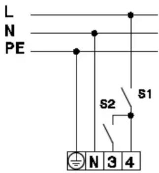
Perform the electrical connection in accordance with the following wiring diagrams. Wiring diagram for speed control on request.
ECO 30 E
text_image
L N PE S2 S1 N 3 4ECO 40 D
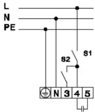
text_image
L N PE 82 81 N 3 4 5-
Insert the cover [3] on the bearing bracket such that it audibly latches at the four corners. Ensure correct seating of the cable grommet [4] → Fig. I.
-
Carefully swivel the fan unit towards the middle and insert the pin of the eccentric lever [12]. Ensure the correct position of the bearing bushing. The job is done!
12. Commissioning
- Pay special attention to the safety instructions and warnings in Chapter 4.
UK | 11. Mounting
- Switch on mains fuse, remove warning sign.
- Run function test. The fan must oscillate in the swivelling range (swivel back and forth).
13. Maintenance
The unit is maintenance-free.
14. Cleaning

The fan must be cleaned regularly, especially after longer downtimes.
NOTICE:
Unit damage in the case of incorrect cleaning. Do not use aggressive cleaning agents.
→ Only clean the unit with a soft cloth → Do not remove protective cage.
- Switch off mains fuse, secure against being accidentally switched back on and position a visible warning sign. Comply with the 5 safety regulations.
- Clean the bearing bracket and fan unit with a dry cloth.
- In the case of a heavily soiled protective cage, clean the cage with a damp cloth.
- Switch on mains fuse, remove warning sign.
Fault finding and repairs should only be carried out by trained specialists.
| Fault Cause, measure | |
| Fan does not switch on. | No mains voltage.Check whether the mains fuse has failed. Switch on if necessary. |
| Motor's thermal overload protection has switched the fan off. | Motor too hot. The motor protection switch has switched off the fan. Wait until the motor has cooled off. The cool-down time can take up to 10 minutes. NOTICE: The unit switches back on automatically after cooling down. |
| Fan does not switch on. | Impeller blocked. Check impeller and clean if necessary. |
| Deposits on the impeller caused by dust in the air. | Imbalance if the impeller is soiled or running irregularly. Clean unit with a damp cloth. |
| Impeller not turning. | Switch off unit. Ensure that the impeller is not blocked by foreign bodies. |

If faults reoccur, send the unit to our factory for repairs.
- Spare parts
| Spare parts | Article no. ECO 30 E | Article no. ECO 40 D |
| Impeller 0060.0042.0001 0060.0044.0001 | ||
| Protective cage, complete | On request E150.0018.0001 | |
| Protective cage – upper part | 0150.0015.0001 | 0150.0018.0001 |
| Protective cage – lower part | 0150.0014.0000 | 0150.0017.0000 |
| Fan motor | 0089.0109.0002 | 0089.0110.0001 |
| Drive motor | 0156.0023.0000 | 0156.0023.0000 |
| Bearings (bearing bushing) | 0190.0028.0000 | 0190.0028.0000 |
| Capacitor0.1 μFGear motor (inside housing [10]) | 0157.0503.0000 | 0157.0503.0000 |
| Capacitor2 μFFan motor | 0157.1203.0000 | |
| Ball bearing | 0190.0007.0000 | 0190.0007.0000 |
Address for orders
Dismantling may only be undertaken by an electrician.
- Switch off mains fuse, secure against being accidentally switched back on and position a visible warning sign. Comply with the 5 safety regulations.
- Remove cover [4] and remove unit.
18. Environmentally responsible disposal
The unit and the packaging contain parts that can be recycled, and should not end up in the domestic waste.
Dispose of the packaging material in an environmentally-friendly way, in compliance with the regulations valid in the country where you are.
At the end of its service life, dispose of the unit in an environmentally-friendly way, in compliance with the regulations valid in the country where you are.
ECO 30 E, ECO 40 D