RTH7560E1001/E - Thermostat HONEYWELL - Free user manual and instructions
Find the device manual for free RTH7560E1001/E HONEYWELL in PDF.

User questions about RTH7560E1001/E HONEYWELL
0 question about this device. Answer the ones you know or ask your own.
Ask a new question about this device
Download the instructions for your Thermostat in PDF format for free! Find your manual RTH7560E1001/E - HONEYWELL and take your electronic device back in hand. On this page are published all the documents necessary for the use of your device. RTH7560E1001/E by HONEYWELL.
USER MANUAL RTH7560E1001/E HONEYWELL
text_image
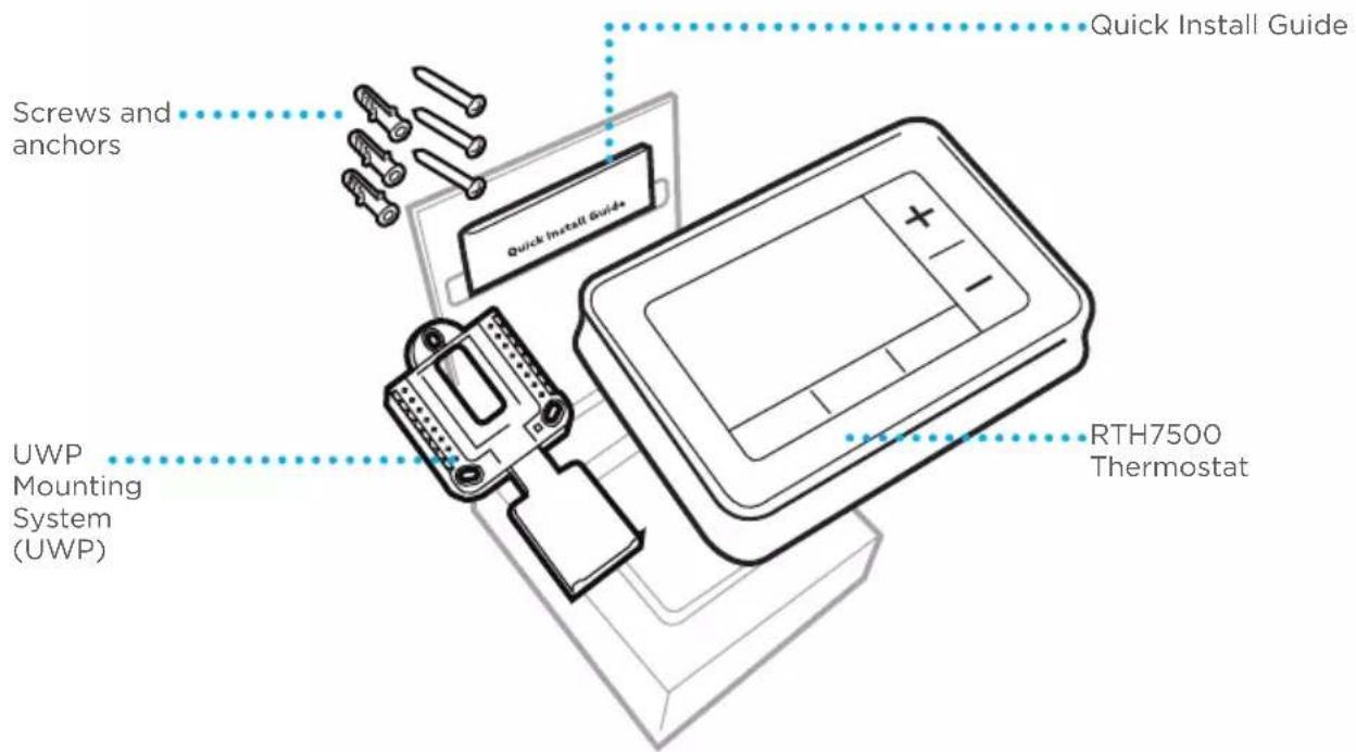
Honeywell 700°C Following Schedule Heat 72 Fan Auto Mode Menu FanIncluded in your box
text_image
Screws and anchors Quick Install Guide UWP Mounting System (UWP) RTH7500 Thermostat Quick Install GuideTools you will need Tools you may need
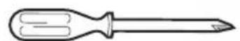
Phillips screwdriver
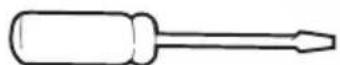
Small flat head screwdriver
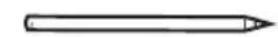
Pencil
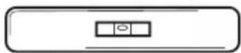
Level
text_image
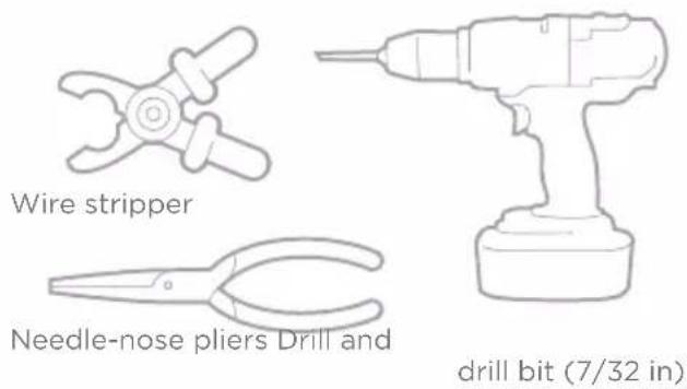
Wire stripper Needle-nose pliers Drill and drill bit (7/32 in)Removing your old thermostat
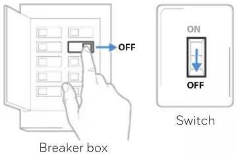
1 Turn power OFF.

To protect yourself and your equipment, Turn off the power at the breaker box or switch that controls your heating/cooling system.
text_image
OFF Breaker box ON OFF Switch2 Check that your system is off.
Change the temperature on your old thermostat. If you don't hear the system turn on within 5 minutes, the power is off.
text_image
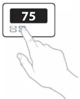
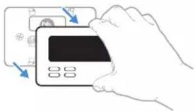
753 Remove the old thermostat's faceplate.
On most thermostats, you can take off the faceplate by grasping and gently pulling. Some thermostats may have screws, buttons, or clasps.
text_image
Diagram showing a hand holding a credit card with arrows pointing to the card's screen and buttons, indicating payment or payment process.
Do not remove any wires from your thermostat at this time!
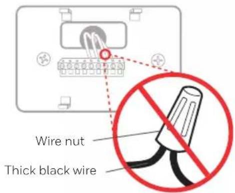
4 Make sure there are no 120/240V wires.

Do you have thick black wires with wire nuts?
Is your thermostat 120V or higher?
If you answered yes to either of these questions, you have a line voltage system and the thermostat will not work.
If you are unsure visit: yourhome.honeywell.com/support
text_image
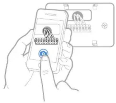
Wire nut Thick black wire5 Take a picture of how your wiring looks right now.
Be sure to include the letters next to the terminals where the wires are inserted. This will be a helpful reference when wiring your thermostat.
Tip: If the color of your wires has faded or if 2 terminals have the same wire color, use the wire labels provided in the package to label each wire.
text_image
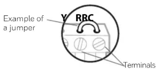
Illustration showing a hand holding a smartphone displaying a device with icons and labels, alongside a device with a logo and control buttons.6 Remove any jumpers
A jumper connects one terminal to another terminal. It may look like a small staple or even a colored wire and must be removed before continuing. Use a screwdriver to release wires from terminals.
text_image
Example of a jumper Y RRC TerminalsThe RTH7500 thermostat does not need jumpers.
7 Record if you have wires in the following terminals.
Do not include jumpers as a part of your count. The thermostat does not need jumpers.
Terminal Wire Color
text_image
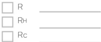
□ R □ RH □ Rc8 Write down the color of the wires.
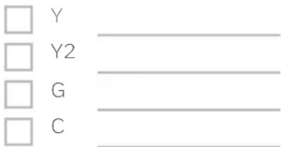
Check mark the wires that are connected to terminals. Next to the check mark, write down the color of the wire. Do not include jumpers as a part of your count.
Check all that apply (Not all will apply):
Terminal Wire Color
text_image
Y Y2 G CTerminal Wire Color
| □ A or L/A |
| □ O/B |
| □ W2 or AUX |
| □ E |
| □ W |
| □ K |
The RTH7500 thermostat does not support L/A, S, or U terminals.
If there are wires in terminals that are not listed, you will need additional wiring support. Visit yourhome.honeywell.com/support to find out if the thermostat will work for you.
9 Disconnect the wires and remove the old wall plate.
Use a screwdriver to release wires from terminals. Then, use a wire label to identify each wire as it's disconnected. The letter on the wire label should match the letter on the terminal.
Tip: To prevent wires from falling back into the wall, wrap the wires around a pencil.
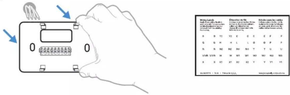
text_image
Writing Labels Apply these writing keys to with the right-hand box to ensure details tended information as you returned from the editing the board. S B Y2 Y2 C C E E F F G G H H L L O O P P R R RC RC RH NH T T U U VWR VWR W W W1 W1 W2 W2 W3 W3 X X X1 X1 X2 X2 Y Y Y1 Y1 SA 160075 + S 18 + P 4000000000000000000000000000000000000000000000000000000000000000000000000000000000000000000000000Installing your RTH7500 thermostat
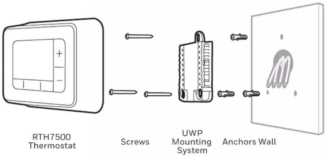
flowchart
graph LR
    A["RTH7500 Thermostat"] --> B["Screws"]
    B --> C["UWP Mounting System"]
    C --> D["Anchors Wall"]
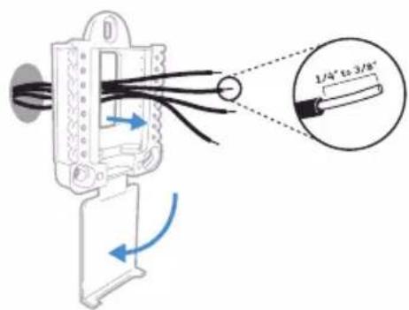
10 Bundle and insert wires through the UWP.
Pull open the UWP and insert the bundle of wires through the back of the UWP. Make sure at least 1/4-inch of each wire is exposed for easy insertion into the wire terminals.
text_image
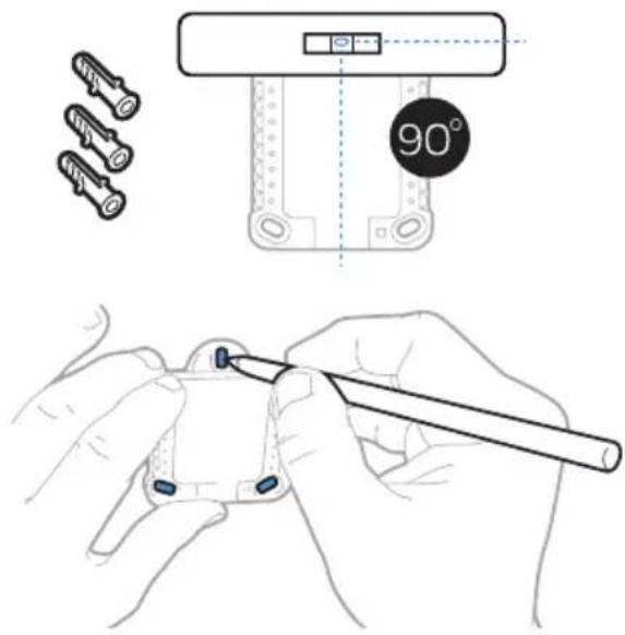
1/4" to 3/8"11 Insert the wall anchors.
It is recommended that you use the wall anchors included in the box to mount your thermostat.
You can use the UWP to mark where you want to place the wall anchors.
a) Level the wall plate.
b) Mark the location of the wall anchors using a pencil.
c) Drill the holes.
d) Insert wall anchors.
e) Make sure anchors are flush with wall.
Tip: Use a 7/32 drill bit.
text_image
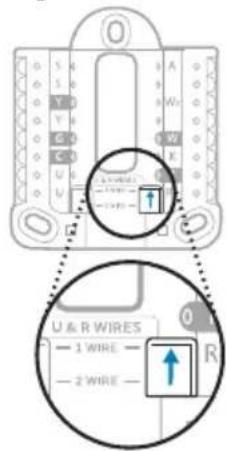
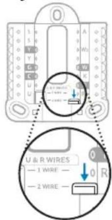
Technical diagram showing a 90-degree angle measurement setup with tool application and component illustrations12 Set R-switch position and insert R-wire or wires.
Set the R-switch up or down based on your wiring notes in Step 7.

Insert wires into the inner holes of the terminals on the UWP. The tabs will stay down once the wire is inserted.
If you have 1 R-wire (R,Rh, or Rc)
text_image
U & R WIRES 1 WIRE 2 WIRE- Set R-switch to the up position.
text_image
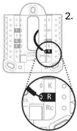
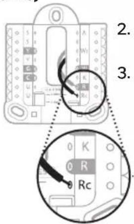
2.- Insert your R-wire (R, Rh or Rc) into R-terminal.
or
If you have 2 R-wires (R or Rh, and Rc)
text_image
U & R WIRES — 1 WIRE — — 2 WIRE —- Set R-switch to the down position.
text_image
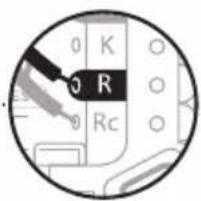
2. 3.- Insert your Rc wire into Rc-terminal
- Insert your R or Rh wire into R-Terminal.
text_image
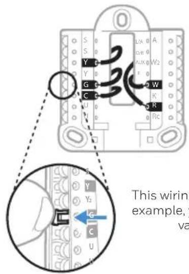
0 K 0 R 0 Rc13 Connect wires from Step 8.
Tip: Do not mount the UWP to the wall prior to connecting the wires.
Depress the tabs to put the wires into the inner holes of their corresponding terminals on the UWP (one wire per terminal) until it is firmly in place.
Gently tug on the wires to verify they are secure.
Tip: If you need to release the wires again, push down the terminal tabs on the sides of the UWP.
text_image
S 0 S 0 Y 0 Y 0 G 0 C 0 U 0 D LXA 0 A OVB 0 AUX 0 W2 F 0 W K R 0 RC This wiring example, y vaThis wiring is just an example, yours may vary.
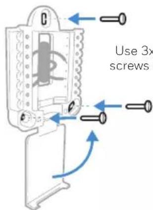
14 Mount the UWP and close the door.
Mount the UWP using the provided screws. Install all three screws for a secure fit on your wall. Close the door after you're finished.
15 Confirm wiring matches snapshot.
Please confirm wiring matches terminals from the photo you took in Step 5.
text_image
Use 3x screws :Use 3x supplied screws #8 1-1/2"
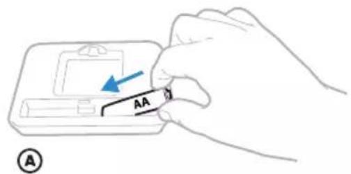
16 Install batteries.
Insert two AA alkaline batteries in the back of the thermostat as shown.
text_image
AA ①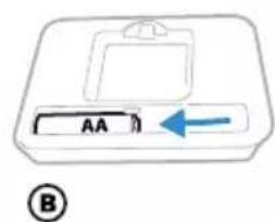
text_image
AA ⑧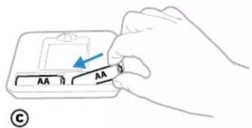
text_image
AA AA ©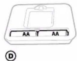
text_image
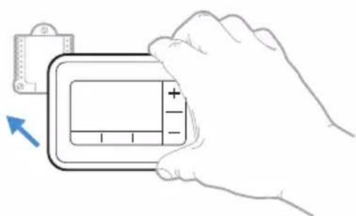
AA AA D17 Attach your thermostat.
Align the thermostat onto the UWP and firmly snap it into place.
natural_image
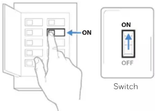
Illustration of a hand holding a digital device with a plus sign, no text or symbols present18 Turn your power ON.
Turn on the power at the breaker box or switch that controls the heating/cooling system.
text_image
ON ON OFF SwitchBreaker box
Set date and time
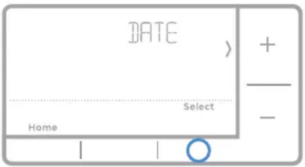
19 Set the date.
Press + or - to adjust the year. Press Select.
Press + or - to adjust the month.
Press Select.
Press + or - to adjust the day. Press Select.

text_image
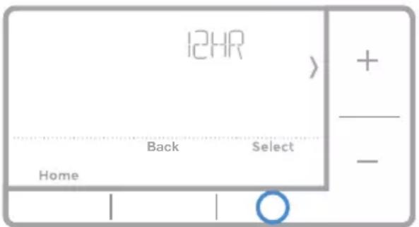
DATE Home Select + -20 Choose a clock format.
Press + or - set the clock format: 12 hour (standard for North America) or 24 hour. Press Select.
text_image
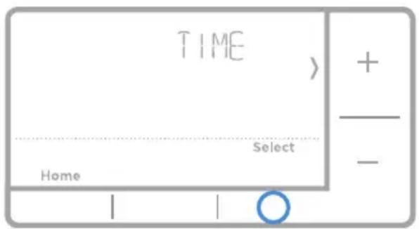
12HR Home Back Select + - ○21 Set the time.
Press + or - to adjust the hour. Press Select.
Press + or - to adjust the minutes. Press Select.
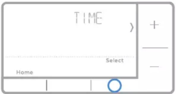
text_image
TIME Home Select + -System Setup
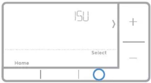
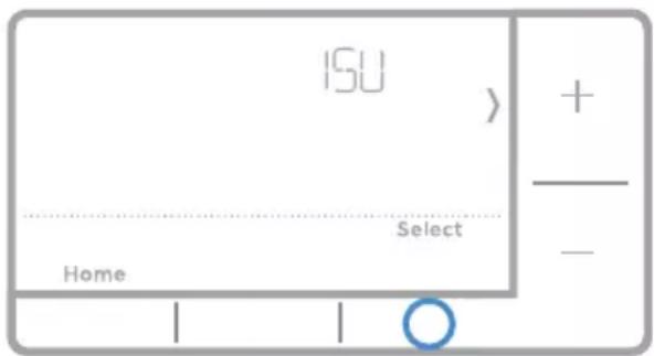
22 Select System Setup options.
Press + or - to change values or select from available options. Then press Select to save changes and advance to the next System Setup number.
See "System Setup options" below for a full list of System Setup numbers and options.
Repeat until all of the System Setup options have been set. The thermostat will automatically save and exit to the Home screen.
23 Continue to "System operation settings" on page 10.
text_image
ISU + - Select Home O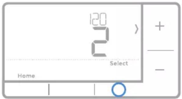
text_image
120 2 2 Home Select + - ○System Setup options
| Number | Description Options (factory default in bold) | |
| 120 Scheduling Options | 0 = Non-Programmable1 = 1-Week Programmable2 = 5-2 Programmable4 = 7-Day ProgrammableNote: You can change default MO-FR, SA-SU schedule here. To edit periods during days, temperature setpoints, or to turn Schedule On/Off, touch MENU and go to SCHEDULE. | |
| 125 Temperature Indication Scale | 0 = Fahrenheit1 = Celsius | |
| 200 Heating System Type | 1 = Conventional Forced Air Heat2 = Heat Pump3 = Radiant Heat5 = None (Cool Only)Note: This option selects the basic system type your thermostat will control. | |
| 205 Heating Equipment Type | Conventional Forced Air Heat:1 = Standard Efficiency Gas Forced Air2 = High Efficiency Gas Forced Air3 = Oil Forced Air4 = Electric Forced Air5 = Hot Water Fan CoilHeat Pump:7 = Air to Air Heat PumpRadiant Heat:9 = Hot Water Radiant Heat12 = SteamNote: This option selects the equipment type your thermostat will control. Note: This feature is NOT displayed if feature 200 is set to Cool Only. | |
| Number | Description Options (factory default in bold) | |
| 218 Reve | sing Valve O/B | 0 = 0 (O/B in Cool)1 = B (O/B in Heat)Note: This option is only displayed if the Heat Pump configured. Select whether reversing valve O/B should energize in cool or in heat. |
| 220 | Cool Stages / Compressor Stages 200=Conv / 200=HP | 0,1,2Note: Select how many Cool or Compressor stages of your equipment the thermostat will control. Maximum of 2 Cool/Compressor Stages. Set value to 0 if you do not have Cool Stage/Compressor Stage. |
| 221 | Heat Stages / Backup Heat Stages Heat Stages | Heat Stages: 1, 2Backup Heat Stages: 0, 1Note: Select how many Heat or Aux/E stages of your equipment the thermostat will control. Maximum of 2 Heat Stages for conventional systems. Maximum of 1 Aux/E stage for systems with more than 1 heating equipment type. Set value to 0 if you do not have Heat Stage/ Backup Heat Stage. |
| 300 System | Changeover | 0 = Manual1 = AutomaticNote: Thermostat can automatically control both heating and cooling to maintain the desired indoor temperature. To be able to select "automatic" system mode on thermostat home screen, turn this feature ON. Turn OFF if you want to control heating or cooling manually. |
| 425Smart | Response | 0 = No1 = YesNote: Smart Response is a comfort setting. Heat or Cooling equipment will turn on earlier, ensuring the indoor temperature will match the setpoint at the scheduled time. |
| 430 | Minimum Cool Temperature Setpoint | 50 °F to 99 °F (50 °F)10.0 °C to 37.0 °C (10.0 °C)Note: The cool temperature cannot be set below this level. |
| 431 | Maximum Heat Temperature Setpoint | 40 °F to 90 °F (90 °F)4.5 °C to 32.0 °C (32.0 °C)Note: The heat temperature cannot be set above this level. |
| 711 | Air Filter 1 Replacement Reminder | 0 = Off1 = 10 Run Time Days2 = 20 Run Time Days3 = 30 Run Time Days4 = 45 Run Time Days5 = 60 Run Time Days6 = 90 Run Time Days7 = 120 Run Time Days8 = 150 Run Time Days9 = 30 Calendar DaysNote: Set a reminder for when to change your air filter. Choose either calendar or equipment run time-based reminder.10 = 45 Calendar Days11 = 60 Calendar Days12 = 75 Calendar Days13 = 3 Calendar Months14 = 4 Calendar Months15 = 5 Calendar Months16 = 6 Calendar Months17 = 9 Calendar Months18 = 12 Calendar Months19 = 15 Calendar Months |
| 1415 Day | light saving time | 0 = Off1 = OnNote: Set to Off in areas that do not follow Daylight Saving Time. |
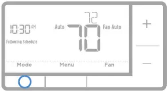
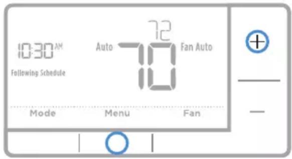
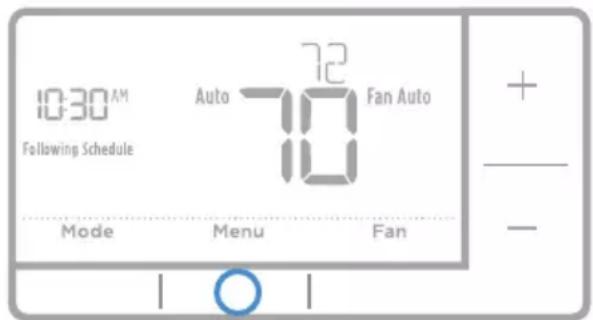
System operation settings
1 Press the Mode button to cycle to the next available System mode.
2 Cycle through the modes until the required System mode is displayed and leave it to activate.
NOTE: Available System modes vary by model and system settings.
System modes:
- Auto: Thermostat selects heating or cooling as needed.
- Heat: Thermostat controls only the heating system.
- Cool: Thermostat controls only the cooling system.
- Em Heat (only for heat pumps with auxiliary heat): Thermostat controls Auxiliary Heat. Compressor is not used.
- Off: Heating and cooling system is off. Fan will still operate if fan is set to On or Circulate.
NOTE: Heat/Cool flash for 5 minutes due to compressor protection.
Fan operation settings
1 Press the Fan button to cycle to the next available Fan mode.
2 Cycle through the modes until the required Fan mode is displayed and leave it to activate.
NOTE: Available Fan modes vary with system settings.
Fan modes:
- Auto: Fan runs only when the heating or cooling system is on.
- On: Fan is always on.
- Circ: Fan circulates randomly about 33% of the time.
text_image
10:30 AM Following Schedule Auto 72 Fan Auto Mode Menu Fan + - -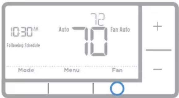
text_image
10:30 AM Following Schedule Auto 72 Fan Auto 10 Mode Menu Fan + - -Program Schedule
You can program four time periods each day, with different settings for weekdays and weekends. We recommend the pre-set settings (shown in the table below), since they can reduce your heating/cooling expenses.
Wake - Set to the time you wake up and the temperature you want during the morning, until you leave for the day.
Away - Set to the time you leave home and the temperature you want while you are away (usually an energy-saving level).
Home - Set to the time you return home and the temperature you want during the evening, until bedtime.
Sleep - Set to the time you go to bed and the temperature you want overnight (usually an energy-saving level).
| Heat Cool | ||
| Wake(6:00 am) | 70° | 78° |
| Away(8:00 am) | 62° | 85° |
| Home(6:00 pm) | 70° | 78° |
| Sleep(10:00 pm) | 62° | 82° |
The above table is only an example.
NOTE: To temporarily or permanently override any of the above program schedules, see page 12.
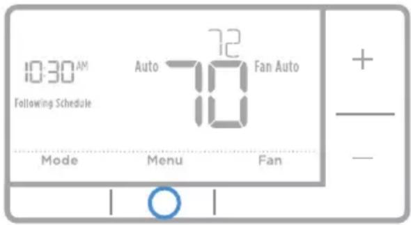
To adjust program schedules
1 Press Menu on your thermostat.
2 PROG is displayed. Press Select. Then ON is displayed. Press Select.
3 Press + or - to select day or set of days to edit. Press Select.
4 Press + or - to select a schedule period to edit (Wake, Away, Home, and Sleep). Press Select.
5 ON is displayed. Press Select to keep the schedule period on. Or press + and then Select to turn off the schedule period.
6 Time starts blinking. Press + or - to adjust the schedule period start time. Press Select.
7 Temperature starts blinking. Press + or - to adjust the "Heat" setpoint temperature. Press Select. Press + or - to adjust the "Cool" temperature setpoint. Press Select.
8 Repeat steps 4 through 7 for the remaining schedule periods.
9 Press Home when you're finished to save program settings and return to the home screen.
text_image
10:30 AM Following Schedule Auto 72 Fan Auto Mode Menu Fan + - -
text_image
Mon Tue Wed Thu Fri Sat Sun Wake Away Home Sleep 6:30 AM 78 Cool Back Select Home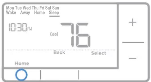
text_image
Mon Tue Wed Thu Fri Sat Sun Wake Away Home Sleep 10:30 PM Cool 76 Back Select Home + - -Program schedule override (temporary)
1 Press + or - to adjust the temperature.
2 Once at the desired setpoint temperature, no further action is needed. The new setpoint temperature will be held until the next scheduled time period begins. For more information on schedule time periods, see “Program Schedule” on page 11.
3 To cancel the Temporary Hold, Press + or - and then press Cancel.

text_image
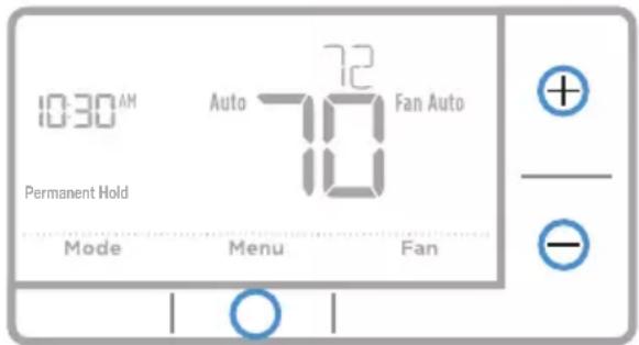
10:30 AM Auto 72 Fan Auto Temporary Hold Mode Menu FanProgram schedule override (permanent)
1 Press + or - to adjust the temperature.
2 TEMPORARY HOLD is displayed and the setpoint temperature flashes. While it's flashing, press Hold (Mode) button to change to Permanent Hold.
3 To cancel the Permanent Hold, press + or - and then press Cancel.
text_image
10:30 AM Auto 72 Fan Auto Permanent Hold Mode Menu FanWiring—conventional systems
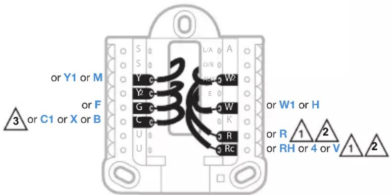
Alternate wiring (conventional systems)
If labels do not match terminals, connect wires as shown below (see notes, below).
NOTES:
- If you must connect both R and Rc wires, set the R Slider Tab to the down position (2 wires).
- If your old thermostat had both R and RH wires, set the R Slider Tab to the down position (2 wires). Then connect the R wire to the Rc terminal, and the RH wire to the R terminal.
- If your old thermostat had only 1 C or C1 wire, connect it to the C terminal. If your old thermostat had 2 C or C1 wires, wrap each separately with electrical tape and do not connect them.
text_image
or Y1 or M or F 3 or C1 or X or B L/A A Y Y2 G C U U W2 W E W K R Rc or W1 or H or R 1 2 or RH or 4 or V 1 2Wiring—heat pump
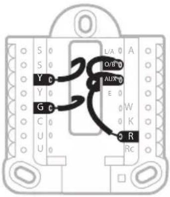
Connect wires: heat pump
1 Match each labeled wire with same letter on new thermostat.
2 Insert the wires into the matching terminal.
NOTE: If you have difficulty inserting wires, you may have to press down the terminal push button next to the corresponding terminal.
Labels don't match?
If labels do not match letters on thermostat, see page 13.
text_image
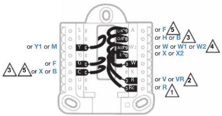
S Y G C U U L/A A O/B AUX E W K R RcAlternate wiring (for heat pumps only)
NOTES:
-
Keep R Slider Tab in the up position (1 wire).
-
If your old thermostat had both V and VR wires, stop now and contact a qualified contractor for help.
-
If your old thermostat had separate O and B wires, attach the B wire to the C terminal. If another wire is attached to the C terminal, stop now and contact a qualified contractor for help.
-
If your old thermostat had Y1, W1 and W2 wires, stop now and contact a qualified contractor for help.
text_image
or Y1 or M 3 5 or F or X or B L/A A Y O/B W2 Y2 E G W C K R Rc or F 5 or H or B 3 or W or W1 or W2 4 or X or X2 or V or VR 2 or R 1Advanced menu
1 Press and hold Menu and + buttons for approximately 5 seconds to enter advanced menu.
text_image
10:30 AM Following Schedule Auto 72 Fan Auto Mode Menu Fan2 Press Select to enter System Setup (ISU) menu.
3 Press Select to cycle through System Setup numbers.
NOTE: See "System Setup options" on page 8 for a full list of System Setup numbers and options.
text_image
ISU + - Select Home | | ○4 Press + or - to change values or select from available options.
5 Press Select to save changes and advance to the next System Setup number.
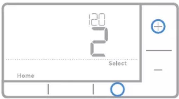
text_image
120 2 2 Select Home - -6 Once you have cycled through all of the System Setup numbers, "Done" is displayed. Press Select to save and exit.
To save and exit early, press Home to return to the Home screen.
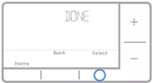
text_image
DONE Home Back Select + - -Smart Response® Technology
This feature allows the thermostat to “learn” how long the furnace and air conditioner take to reach programmed temperature settings, so the temperature is reached at the time you set. For example: Set the Wake time to 6 am, and the temperature to 70°. The heat will come on before 6 am, so the temperature is 70° by the time you wake at 6. The message “Recovery” is displayed when the system is activated before a scheduled time period.
Battery replacement
Batteries are required to provide power. Install fresh batteries immediately when the low battery icon appears. The icon appears about two months before the batteries are depleted.
Even if the low battery icon does not appear, you should replace batteries once a year, or before leaving home for more than a month.
If batteries are inserted within two minutes, the time and day will not have to be reset. All other settings are permanently stored in memory, and do not require battery power.
NOTE: When replacing batteries, alkaline batteries are recommended.
Setting the time
1 Press Menu to enter the device menu. You will see PROG. Press + or - to choose TIME.
2 Press Select.
3 12HR is displayed. Press + or - to choose a 12 hour clock or a 24 hour clock. Press Select.
4 Set the time. Press + or - to adjust the hour. Press Select.
5 Press + or - to adjust the minutes.
Press Select. Press Select to save and exit.
text_image
TIME + - Select Home | | ○Set the date
1 Press Menu to enter the device menu. You will see PROG. Press + or - to choose DATE.
2 Press Select.
3 You will see the year blinking. Press + or - to adjust the year. Press Select.
4 Press + or - to adjust the month.
Press Select.
5 Press + or - to adjust the day. Press Select to save and exit.
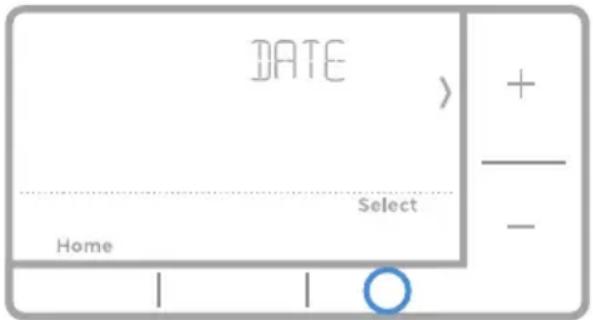
text_image
DATE Home Select + - ○Setting degrees Fahrenheit (F) or Celsius (C)
1 Press Menu to enter the device menu. You will see PROG. Press + or - to choose F/C.
2 Press Select.
3 You will see F or C displayed.
4 Press + or - to adjust to the desired setting. F for Fahrenheit and C for Celsius. Press Select to save and exit.
Alerts screen
1 You will see the alert icon ⚠ on the home screen. You can access alerts in the Menu to view the error/alert code. Once viewed the home screen will maintain the alert symbol until it is cleared.
text_image
10:30 AM Following Schedule Auto 72 Fan Auto Mode Menu Fan + - -2 Snoozed alerts will appear 7 days after dismissing them in the alerts menu screen.
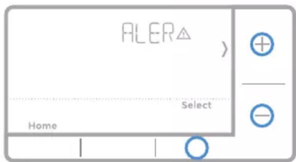
text_image
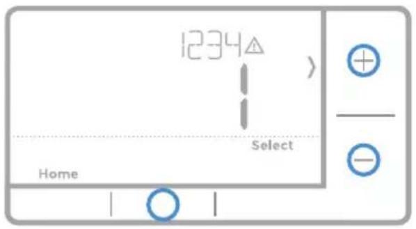
ALER△ Home Select Home + - -3 When the alert icon appears, check the error code with the table below to determine the problem.
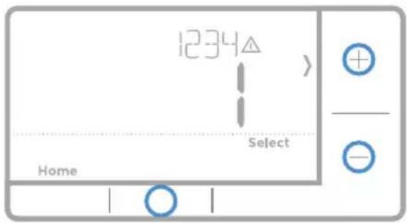
text_image
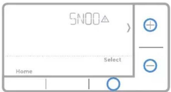
1234 Home Select + - -4 Snooze the alert.
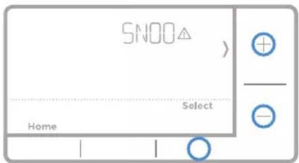
text_image
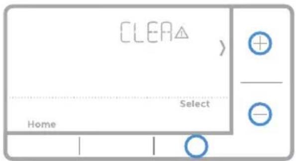
SNOO Home Select + - ○5 Dismiss the alert.
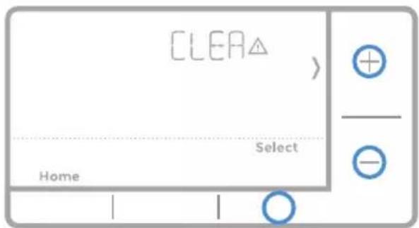
text_image
CLEA Home Select + - ○Alerts codes
| Number | Alert/Reminder Definition | |
| 164 | Heat Pump Needs Service | Heat pump needs service. Contact dealer to diagnose and service heat pump. |
| 170 | Internal Memory Error | The memory of the thermostat has encountered an error. Please contact dealer for assistance. |
| 173 | Thermostat Temperature Sensor Error | The sensor of the thermostat has encountered an error. Please contact dealer to replace the Thermostat. |
| 181 | Replace Air Filter (1) Replace air filter (1). Reset the timer by touching the "dismiss" button on thermostat screen after it is replaced. | |
| 405 | Low Battery Alert | The batteries are getting low. Replace them within two months. |
| 407 | Critical Low Battery The batteries are almost depleted and should be replaced as soon as possible. | |
Troubleshooting
If you have difficulty with your thermostat, please try the following suggestions. Most problems can be corrected quickly and easily.
| Display is blank If you're using batteries, make sure fresh AA alkaline batteries are properly installed (see page 6). | |
| Cannot change system setting to Cool | Check System Setup Option 220 to make sure the options are set to either 1 or 2 (see page 9). |
| Fan does not turn on when heat is required | Check System Setup Option 205 to make sure it is set to match your heating equipment (see page 8). |
| Heating system is running in cool mode | Check System Setup Option 200 or 218 to make sure it is set to match your heating and cooling equipment (see page 9). |
| Heating or cooling system does not respond | Press System to set system to Heat. Make sure the temperature is set higher than the Inside temperature. Press System to set system to Cool. Make sure the temperature is set lower than the Inside temperature. Check circuit breaker and reset if necessary. Make sure power switch at heating & cooling system is on. Make sure furnace door is closed securely. Wait 5 minutes for the system to respond. |
| Heat On / Cool On flashing on the screen | Compressor protection feature is engaged. Wait 5 minutes for the system to restart safely, without damage to the compressor. |
| Heat pump issues cool air in heat mode, or warm air in cool mode | Check System Setup Option 200 or 218 to make sure it is set to match your heating and cooling equipment (see page 9). |
1-year limited warranty
Honeywell warrants this product, excluding battery, to be free from defects in the workmanship or materials, under normal use and service, for a period of one (1) year from the date of purchase by the consumer. If at any time during the warranty period the product is determined to be defective or malfunctions, Honeywell shall repair or replace it (at Honeywell's option).
If the product is defective,
(i) return it, with a bill of sale or other dated proof of purchase, to the place from which you purchased it; or
(ii) call Honeywell Customer Care at 1-800-468-1502. Customer Care will make the determination whether the product should be returned to the following address: Honeywell Return Goods, Dock 4 MN10-3860, 1985 Douglas Dr. N., Golden Valley, MN 55422, or whether a replacement product can be sent to you.
This warranty does not cover removal or reinstallation costs. This warranty shall not apply if it is shown by Honeywell that the defect or malfunction was caused by damage which occurred while the product was in the possession of a consumer.
Honeywell's sole responsibility shall be to repair or replace the product within the terms stated above. HONEYWELL SHALL NOT BE LIABLE FOR ANY LOSS OR DAMAGE OF ANY KIND, INCLUDING ANY INCIDENTAL OR CONSEQUENTIAL DAMAGES RESULTING, DIRECTLY OR INDIRECTLY, FROM ANY BREACH OF ANY WARRANTY, EXPRESS OR IMPLIED, OR ANY OTHER FAILURE OF THIS PRODUCT. Some states do not allow the exclusion or limitation of incidental or consequential damages, so this limitation may not apply to you.
THIS WARRANTY IS THE ONLY EXPRESS WARRANTY HONEYWELL MAKES ON THIS PRODUCT. THE DURATION OF ANY IMPLIED WARRANTIES, INCLUDING THE WARRANTIES OF MERCHANTABILITY AND FITNESS FOR A PARTICULAR PURPOSE, IS HEREBY LIMITED TO THE ONE-YEAR DURATION OF THIS WARRANTY.
Some states do not allow limitations on how long an implied warranty lasts, so the above limitation may not apply to you. This warranty gives you specific legal rights, and you may have other rights which vary from state to state.
If you have any questions concerning this warranty, please write Honeywell Customer Relations, 1985 Douglas Dr, Golden Valley, MN 55422 or call 1-800-468-1502. In Canada, write Retail Products ON15-02H, Honeywell Limited/Honeywell Limitée, 35 Dynamic Drive, Toronto, Ontario M1V4Z9.

CAUTION: ELECTRICAL HAZARD
Can cause electrical shock or equipment damage. Disconnect power before beginning installation.

CAUTION: MERCURY NOTICE
If this product is replacing a control that contains mercury in a sealed tube, do not place the old control in the trash. Contact your local waste management authority for instructions regarding recycling and proper disposal.
Customer assistance
For assistance with this product, please visit http://yourhome.honeywell.com.
Or call Honeywell Customer Care toll-free at 1-800-468-1502.
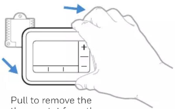
text_image
Pull to remove the thermostat from thePull to remove the thermostat from the UWP.
Automation and Control Solutions
Honeywell International Inc.
1985 Douglas Drive North
Golden Valley, MN 55422
customer.honeywell.com
^6 U.S. Registered Trademark.
© 2016 Honeywell International Inc.
33-00202EF-01 M.S. 08-16
Printed in U.S.A.
Honeywell

text_image
Black and white barcode image with vertical lines on both sides33-00202EF-01
Série RTH7500
Thermostat programmable
text_image
Honeywell 700°F Following Schedule Heat 72 Fan Auto 12 Mode Menu Fantext_image
Illustration of a hand holding a credit card with arrows pointing to the card's screen and buttons
text_image
Illustration showing a hand holding a smartphone displaying a smart device with icons and text, alongside a device with a logo.text_image
□ R □ RH □ Rctext_image
A or L/A O/B W2 or AUX E W Ktext_image
1/4" to 3/8"11 Insérez les ancres murales.
text_image
Technical diagram showing a 90-degree sensor device with three small components and a close-up of hands using a pen to adjust the component.text_image
U & R WIRES 1 WIRE - 2 WIRE - 1 WIRE -text_image
0 K 0 R 0 Rcnatural_image
Illustration of a hand holding a digital device with a plus/− button, showing no text or symbols on the device itself.text_image
ISU Home Select + - ○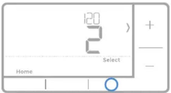
text_image
120 2 2 Select Home + - -text_image
10:30 AM Following Schedule Auto 72 Fan Auto Mode Menu Fan + - -Modes de système :
text_image
10:30 AM Following Schedule Auto 72 Fan Auto Mode Menu Fan + - -text_image
10:30 AM Following Schedule Mode Auto 72 Fan Auto 10 Menu Fan + - -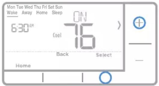
text_image
Mon Tue Wed Thu Fri Sat Sun Wake Away Home Sleep 6:30"N 7:16" Cool 7:16" Back Select Home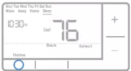
text_image
Mon Tue Wed Thu Fri Sat Sun Wake Away Home Sleep 10:30 PM Cool 76 Back Select Hometext_image
S Y G C U U L/A A D/B AUX E W K R Rctext_image
10:30 AM Following Schedule Auto 72 Fan Auto 10 Mode Menu Fantext_image
DONE Home Back Select + - -Smart Response® Technology
This feature allows the thermostat to "learn" how long the furnace and air conditioner take to reach programmed temperature settings, so the temperature is reached at the time you set. For example: Set the Wake time to 6 am, and the temperature to 70^ . The heat will come on before 6 am, so the temperature is 70^ by the time you wake at 6. The message "Recovery" is displayed when the system is activated before a scheduled time period.
Battery replacement
Batteries are required to provide power. Install fresh batteries immediately when the low battery icon appears. The icon appears about two months before the batteries are depleted.
Even if the low battery icon does not appear, you should replace batteries once a year, or before leaving home for more than a month.
If batteries are inserted within two minutes, the time and day will not have to be reset. All other settings are permanently stored in memory, and do not require battery power.
NOTE: When replacing batteries, alkaline batteries are recommended.
Setting the time
1 Press Menu to enter the device menu. You will see PROG. Press + or - to choose TIME.
2 Press Select.
3 12HR is displayed. Press + or - to choose a 12 hour clock or a 24 hour clock. Press Select.
4 Set the time. Press + or - to adjust the hour. Press Select.
5 Press + or - to adjust the minutes. Press Select.
6 Press Select to save and exit.

text_image
TIME Home Select + - ○Set the date
1 Press Menu to enter the device menu. You will see PROG. Press + or - to chose DATE.
2 Press Select.
3 You will see the year blinking. Press + or - to adjust the year. Press Select.
4 Press + or - to adjust the month.
Press Select.
5 Press + or - to adjust the day. Press Select to save and exit.
text_image
DATE Home Select + -Setting degrees Fahrenheit (F) or Celsius (C)
1 Press Menu to enter the device menu. You will see PROG. Press + or - to choose F/C.
2 Press Select.
3 You will see F or C displayed.
4 Press + or - to adjust to the desired setting. F for Fahrenheit and C for Celsius. Press Select to save and exit.
Alert screen
1 You will see the alert icon ⚠ on the home screen. You can access alerts in the Menu to view the error/alert code. Once viewed the home screen will maintain the alert symbol until it is cleared.
2 Snoozed alerts will appear 7 days after dismissing them in the alerts menu screen.

text_image
10:30 AM Following Schedule Auto 72 Fan Auto 10 Mode Menu Fan + - -
text_image
ALER△ Home Select + - ○3 When the alert icon appears, check the error code with the table below to determine the problem.
text_image
1234 Home Select4 Snooze the alert.
text_image
SNOO Home Select + - ○5 Dismiss the alert.
text_image
CLEAR Home Select + - ○Alerts codes
| Number | Alert/Reminder Definition | |
| 164 | Heat Pump Needs Service | Heat pump needs service. Contact dealer to diagnose and service heat pump. |
| 170 | Internal Memory Error | The memory of the thermostat has encountered an error. Please contact dealer for assistance. |
| 173 | Thermostat Temperature Sensor Error | The sensor of the thermostat has encountered an error. Please contact dealer to replace the Thermostat. |
| 181 | Replace Air Filter (1) Replace air filter (1). Reset the timer by touching the "dismiss" button on thermostat screen after it is replaced. | |
| 405 | Low Battery Alert | The batteries are getting low. Replace them within two months. |
| 407 | Critical Low Battery The batteries | are almost depleted and should be replaced as soon as possible. |
Dépannage
MISE EN GARDE : AVIS RELATIF AU MERCURE
Honeywell International Inc.
1985 Douglas Drive North
Golden Valley, MN 55422
customer.honeywell.com
Honeywell