
5B30N 0250 - Oven BLAUPUNKT - Free user manual and instructions
Find the device manual for free 5B30N 0250 BLAUPUNKT in PDF.
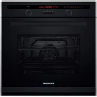



| Brand | Blaupunkt |
| Model | 5B30N 0250 |
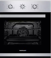
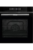
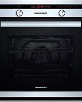
| Product type | Built-in electric oven |
| Dimensions (W x H x D) | 595 x 595 x 560 mm |
| Approximate weight | 30 kg |
| Power supply | 220-240 V ~ 50/60 Hz |
| Maximum power | Not specified (estimated 2500 W) |
| Cooking type | Conventional, fan-assisted, grill, double grill, defrost, eco |
| Temperature range | 50 to 250 °C (depending on function) |
| Timer | Yes, adjustable from 1 min to 9 h 59 |
| Delayed start | Yes, programmable up to 23 h 59 |
| Child safety | Yes, lock by simultaneous press |
| Interior lighting | Halogen lamp 25-40 W / 220-240 V, T 300 °C |
| Included accessories | Grid, drip tray, side support rails |
| Cleaning | Manual, with damp cloth and mild detergent |
| Removable door | Yes, for cleaning and window replacement |
| Energy class | Not specified |
| Energy consumption | Not specified |
| Repairability | Bulb and windows replaceable, spare parts available |
| Warranty | Not specified (standard 2 years) |
Frequently Asked Questions - 5B30N 0250 BLAUPUNKT
User questions about 5B30N 0250 BLAUPUNKT
0 question about this device. Answer the ones you know or ask your own.
Ask a new question about this device
Download the instructions for your Oven in PDF format for free! Find your manual 5B30N 0250 - BLAUPUNKT and take your electronic device back in hand. On this page are published all the documents necessary for the use of your device. 5B30N 0250 by BLAUPUNKT.
USER MANUAL 5B30N 0250 BLAUPUNKT
Instructions on mounting and use 21
Integrated oven 5B30N0250
Built-in oven 5B30N0250


REPLACING THE OVEN LAMP
VENTILATION OPENINGS

Hinge with bracket


ACKNOWLEDGMENT
Thank you for purchasing our product. We hope you enjoy using the many features and benefits it provides. Before using this product, please study this entire Instruction Manual carefully. Keep this manual in a safe place for future reference. Ensure that other people using the product are familiar with these instructions as well.
WARNING
- When the oven is first switched on, it may give off an unpleasant smell. This is due to the bonding agent used for the insulating panels within the oven. Please run the new empty product with the conventional cooking function, 250 °C, for 90 minutes to clean oil impurities inside the cavity.
- During the first use, it is completely normal that there will be slight smoke and odors. If it does occur, you merely have to wait for the smell to clear before putting food into the oven.
- Please use the product in an open environment.
- The appliance and its accessible parts become hot during use. Care should be taken to avoid touching heating elements. Children less than 8 years of age shall be kept away unless continuously supervised.
- If the surface is cracked, switch off the appliance to avoid the possibility of electric shock.
- This appliance can be used by children aged from 8 years and above and persons with reduced physical, sensory or mental capabilities or lack of experience and knowledge if they have been given
supervision or instruction concerning use of the appliance in a safe way and understand the hazards involved. Children shall not play with the appliance. Cleaning and user maintenance shall not be made by children without supervision.
- During use, the appliance becomes very hot. Care should be taken to avoid touching heating elements inside the oven.
- Do not allow children to go near the oven when it is operating, especially when the grill is on.
- Ensure that the appliance is switched off before replacing the oven lamp to avoid the possibility of electric shock.
- The means for disconnection must be incorporated in the fixed wiring in accordance with the wiring specifications. Children should be supervised to ensure that they do not play with the appliance.
- This appliance is not intended for use by persons (including children) with reduced physical, sensory or mental capabilities, or lack of experience and knowledge, unless they have been given supervision or instruction concerning use of the appliance by person responsible for their safety.
- Accessible parts may become hot during use. Young children should be kept away.
- An all-pole disconnection means must be incorporated in the fixed wiring in accordance with the wiring rules.
- If the supply cord is damaged, it must be replaced by the manufacturer, its service agent or similarly qualified persons in order to avoid a hazard.
- Do not use harsh abrasive cleaners or sharp metal scrapers to clean the oven door glass since they can scratch the surface, which may result in shattering of the glass. A steam cleaner is not to be used.
- The appliances are not intended to be operated by means of an external timer or separate remote-control system.
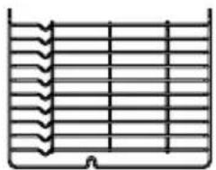
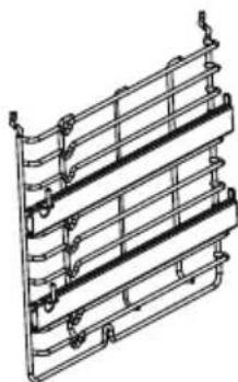
- The instructions for ovens that have shelves shall include details indicating the correct installations of the shelves.
SAFETY HINTS
- Do not use the oven unless you are wearing something on your feet. Do not touch the oven with wet or damp hands.
- For the oven: The oven door should not be opened often during the cooking period.
- The appliance must be installed by an authorized technician and put into use. The producer is not responsible for any damage that might be caused by defective placement and installation by unauthorized personnel.
- When the door or drawer of the oven is open, do not leave anything on it; you may unbalance your appliance or break the door.
- Some parts of the appliance may retain heat for a long time; it is required to wait for it to cool down before touching points that are directly exposed to heat.
- If you will not use the appliance for a long time, it is advised to unplug it.
FITTING THE OVEN INTO THE KITCHEN UNIT
Fit the oven into the space provided in the kitchen unit; it may be fitted underneath a worktop or into an upright cupboard. Fix the oven in position by screwing into place, using the two fixing holes in the frame. To locate the fixing holes, open the oven door and look inside. To allow adequate ventilation, adhere to the measurements and distances when fixing the oven.
IMPORTANT
If the oven is to work properly, the kitchen housing must be suitable. The panels of the kitchen unit that are next to the oven must be made of a heat-resistant material. Ensure that the glues of units made of veneered wood can withstand temperatures of at least 120 °C. Plastics or glues that cannot withstand such temperatures will melt and deform the unit. Once the oven has been lodged inside the units, electrical parts must be completely insulated. This is a legal safety requirement. All guards must be firmly fixed into place so that it is impossible to remove them without using special tools. Remove the back of the kitchen unit to ensure an adequate current of air circulates around the oven. The hob must have a rear gap of at least 35 mm.
DECLARATION OF COMPLIANCE
When you have unpacked the oven, make sure that it has not been damaged in any way. If you have any doubts at all, do not use it: contact a professionally qualified person. Keep packing materials such as plastic bags, polystyrene, or nails out of the reach of children because these are dangerous to children.

PRODUCT DESCRIPTION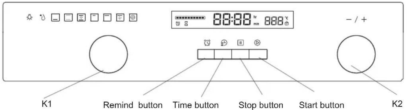
| Symbol | Function description |
 | Oven Lamp: Which enables the user to observe the progress of cooking without opening the door. Oven lamp will light for all cooking functions except for ECO function. |
 | Deforst: The circulation of air at room temperature enables quicker thawing of frozen food, (without the use of any heat). It's a gentle but quick way to speed up the defrosting time and thawing of ready-made dishes and cream filled produce etc. |
 | Bottom heater: A concealed element in the bottom of the oven provides a more concentrative heat to the base of food without browning. This is ideal for slow cooking dishes such as casseroles, stews, pastries and pizzas where a crispy base is desired. The temperature can be set within the range of 60-120 °C. The default temperature is 60 °C. |
 | Conventional cooking: The top and bottom work together to provide convectional cooking. The temperature can be set within the range of 50-250 °C. The default temperature is 220 °C. |
 | Convention with fan: Combination of the fan and both heating element provides more even heat penetration, saving up to 30-40% of energy. Dishes are lightly browned on the outside and still moist on the inside. Note: This function is suitable for grilling or roasting big pieces of meat at a higher temperature. The temper ature can be set within the range of 50-250 °C. The default temperature is 220 °C. |
 | Radiant grilling: The inner grill element switches on and off to maintain temperature. The temperature can be set within the range of 180-240 °C. The default temperature is 210 °C. |
 | Double grill: The radiant heating element and the top heating element are working. The temperature can be set within the range of 180-240 °C. The default temperature is 210 °C. |
 | Double grill with fan: The radiant heating element and top heating element are working with fan. The temperature can be set within the range of 180-240 °C. The default temperature is 210 °C. |
 | Convection: An element around the convection fan provides an additional source of heat for convection style cooking. In convection mode the fan automatically comes on to improve air circulation within the oven and creates an even heat for cooking. The temperature can be set within the range of 50-240 °C. The default temperature is 180 °C. |
 | This is an energy-saving heating function that allows you to gently cook meat, fish and baked items. The appliance optimally controls the supply of energy to the cooking compartment. Depending on the method of preparation and the type of food, it is possible to save energy. |
OPERATION INSTRUCTIONS
1. Clock Setting
After connecting the unit to the power, the symbols "0:00" will be visible on the display.
1> Press "☐", the hour figures will flash. 2> Rotate "K2" to adjust the hour figures (time should be within 0--23). 3> Press "🔒", the minutes will flash. 4> Rotate "K2" to adjust the minutes setting (time should be within 0--59). 5> Press "🔒" to finish the clock settings. ":" will flash, and the time will be illuminated.
Note: The clock is 24 hours. After power on, if not set, the clock will show "0:00".
2. Function Setting
1> Rotate "K1" to choose the cooking function you require. The related symbol will illuminate. 2> Rotate "K2" to adjust the temperature. 3> Press "▶" to confirm the start of cooking. 4> If step 2 is ignored, press "▶" to confirm the start of cooking and the default time is 9 hours, the default temperature will display on the LED.
NOTE:
1> The step quantities for the adjustment time of the knobs are as follows: 0--0:30min: step 1 minute; 0:30--9:00hour: step 5 minutes. 2> The step quantities for the adjustment of temperature is 5°C, and the grill function is 30°C. 3> Rotate "K1" to adjust the cooking time when cooking begins. Then press "▶" to confirm.
If "☐" is not pressed within 3 seconds, the oven will revert back to the previous time to continue cooking.
4> Rotate "K2" to adjust the temperature when cooking begins. The related indicator will be illuminated.
Then press "☑" to start cooking. If "☑" is not pressed in 3 seconds, the oven will revert back to the previous temperature to continue cooking.
3. Lamp Setting
1> Rotate "K1" to select the relevant function, then the corresponding icon will be on. 2> Press "▶" button to start, "0:00" and lamp icon "-☐-" will light up, ":" will flash.
4. Inquiring function
In the following states, you can use the inquiring function; after 3 seconds it returns to the current state.
1> During working state, if the clock was set, press "🔊" button to see the current time; if the reminder function was set, press "🔊" button to see the time of reminder. 2> In reminding state, if the clock was set, press "🔍" button to see the current time. 3> In clock display state, if the reservation function was set, press "🔒" button to see the time of reservation.
5. Child lock function
To lock: press " ▶ " and " □ " simultaneously for 3 seconds, there will be a long "beeping" sound and the " 🔒 " will be illuminated.
To unlock: press " ▶ " and " □ " simultaneously for 3 seconds, there will be a long "beeping" sound indicating the child lock is released.
Note: During working mode, if you want to stop cooking, press the stop button quickly. Do not need to long press the stop button; it is invalid.
6. Reminder Function:
This function helps to remind you to start cooking at a certain time from 0:01 to 9:59.
Only when the oven is in standby mode can the reminder be set. Follow the steps below to set the reminder:
1> Press the reminder setting button " ℓ"; 2> Rotate "K2" to set the hour of the reminder (time should be within 0-9). 3> Press the reminder setting button " ℓ" again; 4> Rotate "K2" to set the minute of the reminder (time should be within 0-59). 5> Press " ▶ " to confirm the setting. The time will count down.
Note: The oven buzzer will sound 10 times after the time returns to zero.
You can cancel the reminder during setting by pressing the "☐" button; after the reminder has been set, you can cancel it by pressing the stop button twice.
7. Start/Pause/Cancel Function
1> If the cooking time has been set, press " ▶" to start cooking. If cooking is paused, press " ▶" to resume cooking. 2> During the cooking process, press " [Ⅲ] " once to pause cooking. Press " [Ⅱ] " twice to cancel cooking.
8. Energy-Saving Function
1> In the waiting state and reminding state, press " ▶" for three seconds, the LED display will go off and set to energy-saving mode. 2> If there is no operation for 10 minutes in the waiting state, the LED display will go off and enter energy-saving mode. 3> In energy-saving mode, press any key or rotate any knob to exit energy-saving mode.
9. Reservation function
1> To use the reservation function, the clock must be set in advance. Then, in the same way as setting the clock, set the reserved time at which the oven starts cooking (a> Press the reservation setting button "☑"); b> Rotate "K2" to set the hour of the reservation. The time should be between 0 and 23. c> Press the reservation setting button "☑" again; d> Rotate "K2" to set the minute of the reservation. The time should be between 0 and 59.), but do not press the clock button this time. Next, turn knob "K1" to choose the function. 2> Press the "▶" button to set the cooking time and temperature. Then turn knob "K1" to adjust the time, and "K2" to adjust the temperature. 3> Press the "▶" button to finish the cooking setting, and the clock will be displayed on the screen with the reservation symbol "∑" always lit. However, no other function signals are shown. The reservation time can be checked by pressing "∑"; 3 seconds later, the screen will show the clock again. 4> At the reserved time, cooking will start automatically after a buzzing sound. The reservation symbol "∑" will turn off, and other indicating signs will work normally.
Note:
- Lamp, defrost, and probe functions cannot be reserved.
- During the reservation status, press the cancel button once; the time and temperature of the reservation menu will be shown with the menu icon lighting constantly. Press again, and the screen returns to the clock, or press the start button to return to the reservation status.
- The reminder function is invalid during the reservation status.
10. Note
1> The oven lamp will be on for all functions. 2> Once the cooking program has been set and the "▶" button is not pressed within 5 minutes, the current time will be displayed or the oven will return to the waiting state. The set program will be invalid. 3> The buzzer will sound once when a button is effectively pressed; if not effectively pressed, there will be no response. 4> The buzzer will sound five times to remind you when cooking has finished.
ACCESSORIES
Wire shelf: For grilling dishes, cake pans with items for roasting and grilling.
Slider bracket: These shelf support rails on the right and left sides of the oven can be removed for cleaning the oven walls. (Only for specific models)
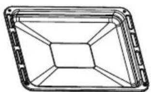
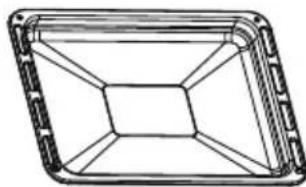
Universal pan: For cooking large quantities of food such as moist cakes, pastries, frozen food, etc., or for collecting fat/spillage and meat juices.
Telescopic runner: Some models might have telescopic runners to facilitate the use of the oven.
These telescopic runners can be disassembled for cleaning by unscrewing the screws used to fix them.
(Only for specific models)


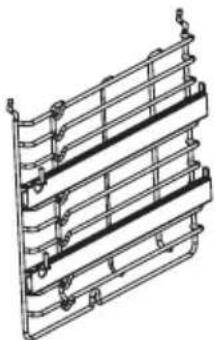
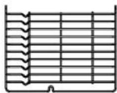
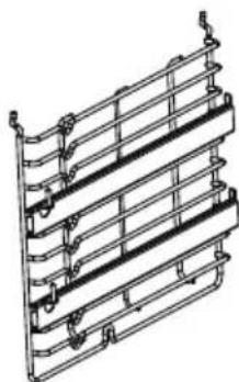
SHELF PLACEMENT WARNING:
To ensure the oven shelves operate safely, correct placement of the shelves between the side rails is imperative. This will ensure that during careful removal of the shelf or tray, hot food items should not slide out.

BULB REPLACEMENT
For replacement, proceed as follows:
1. Disconnect power from the mains outlet or switch off the circuit breaker of the unit's mains outlet. 2. Unscrew the glass lamp cover by turning it counter-clockwise (note, it may be stiff) and replace the bulb with a new one of the same type. 3. Screw the glass lamp cover back in place.
NOTE: Only use 25-40W/220V-240V, T300°C halogen lamps.

SECURING THE OVEN TO THE CABINET
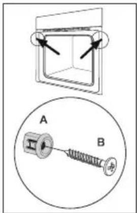
- Fit the oven into the cabinet recess.
- Open the oven door.
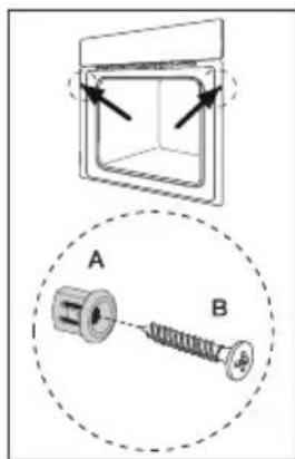
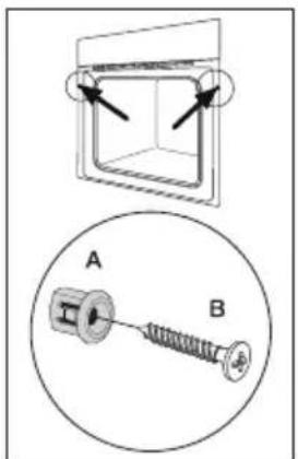
- Secure the oven to the kitchen cabinet with two distance holders "A" which fit the holes in the oven frame and fit the two screws "B".
VENTILATING OPENINGS
When cooking is finished or in pause state or in waiting state, if the oven's center temperature is over 75 degrees, the cooling fan will continue working for 15 minutes. Or when the oven's center temperature becomes lower than 75 degrees, the cooling fan will stop in advance.

INSTALLATION

NOTE: The number of accessories included depends on the particular appliance purchased.
CLEANING AND MAINTENANCE
For the sake of a good appearance and reliability, keep the unit clean. The modern design of the unit facilitates maintenance to a minimum. The parts of the unit which come into contact with food have to be cleaned regularly.
Before any maintenance and cleaning, disconnect the power. Set all controls to the OFF position. Wait until the inside of the unit is not hot but only slightly warm - cleaning is easier when warm. Clean the surface of the unit with a damp cloth, soft brush, or fine sponge, and then wipe dry. In case of heavy soiling, use hot water with a non-abrasive cleaning product. For cleaning the glass of the oven door, do not use abrasive cleaners or sharp metal scrapers, as these can scratch the surface or lead to the glass being damaged. Never leave acidic substances (such as lemon juice or vinegar) on stainless steel parts. Do not use a high-pressure cleaner for cleaning the unit. The baking pans may be washed in mild detergent.
This appliance is marked according to the European directive 2012/19/EU on Waste Electrical and Electronic Equipment (WEEE).
By ensuring this product is disposed of correctly, you will help prevent potential negative consequences for the environment and human health, which could otherwise be caused by inappropriate waste handling of this product. The symbol on the product indicates that this product may not be treated as household waste. Instead, it shall be handed over to the applicable collection point for the recycling of electrical and electronic equipment. Disposal must be carried out in accordance with local environmental regulations for waste disposal. For more detailed information about treatment, recovery, and recycling of this product, please contact your local city office, your household waste disposal service, or the shop where you purchased the product.

Installation instruction of the door frame up cover and rotation bracket assembly
Preparation before disassembly
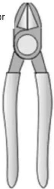
Most of the tools that you might need are shown below. Some tools are optional.

Parts disassembly
The oven door's disassembly
Step 1: Open the oven door completely.
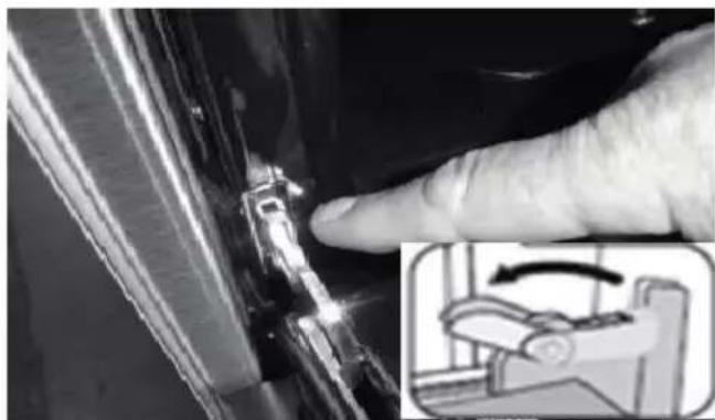
Step 2: Pull the hinge locks forward on both hinges, until they stop.

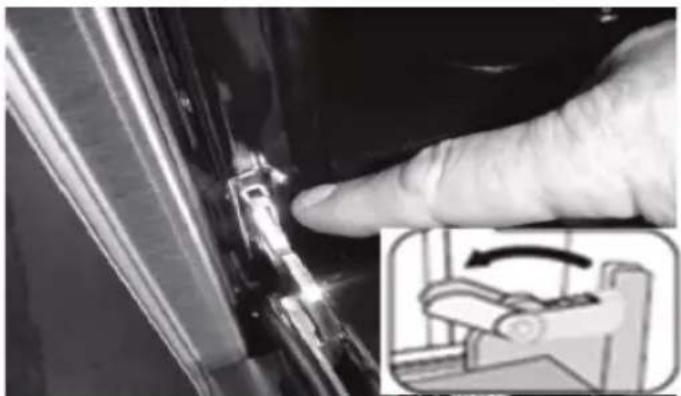
Hinge Lock
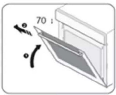
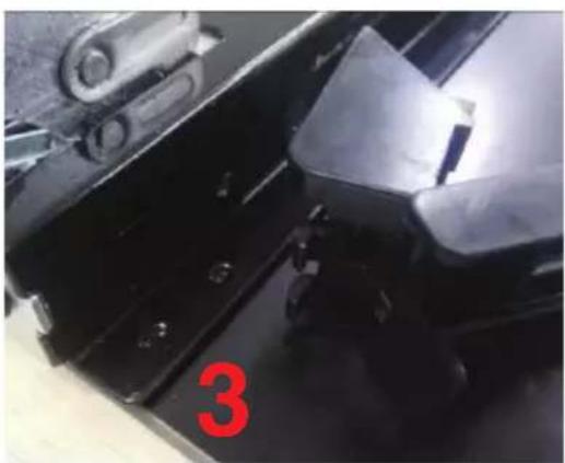
Step 3: Raise the door so that it is at a 30° angle from the front of the oven. Hold the door with one hand on each side. Lift the door up and out.


Warning: Do not forcibly pull out the door and prevent the glass breakage during the dismantling process.
Warning: The hinge springs could release, causing personal injury.
Warning: Do not lift or carry the oven door by the door handle.
The oven door components' disassembly.
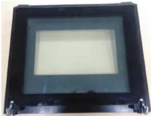
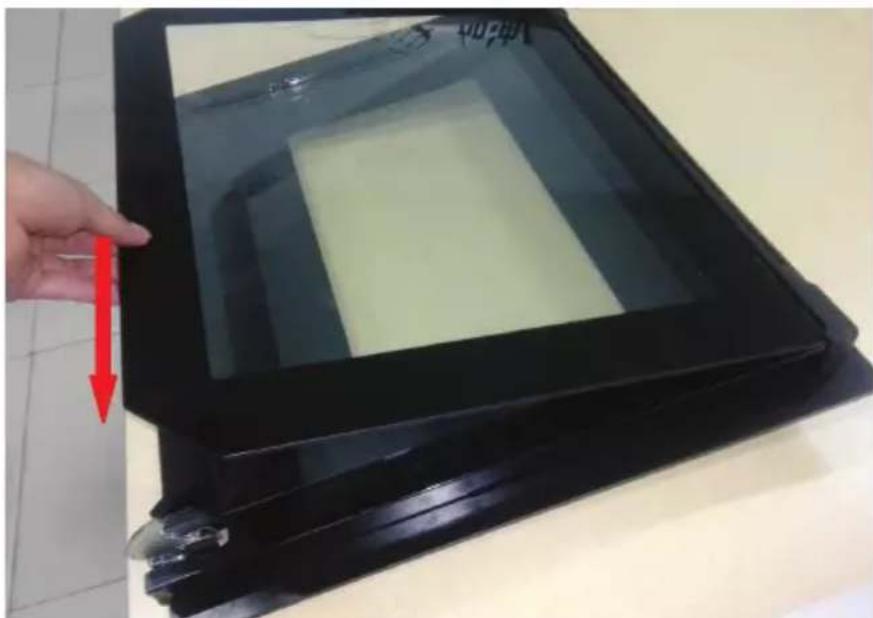
Step 1: Disassemble the door from the oven, then put it on the bench horizontally, see 2.1.
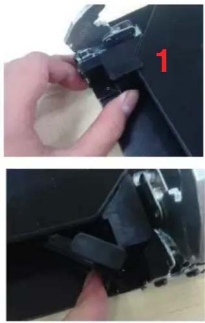
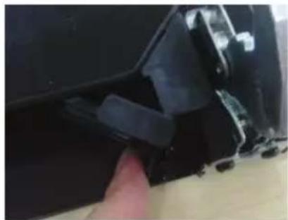
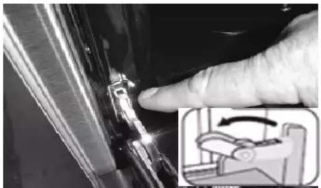
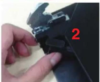
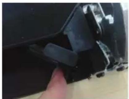
Step 2: Open the door rotation bracket assembly, refer the action in the following picture.


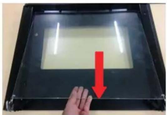
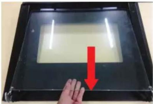
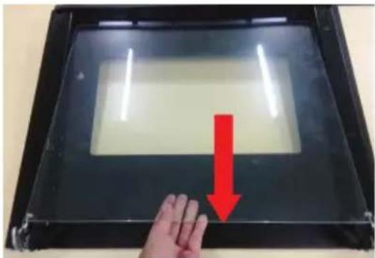
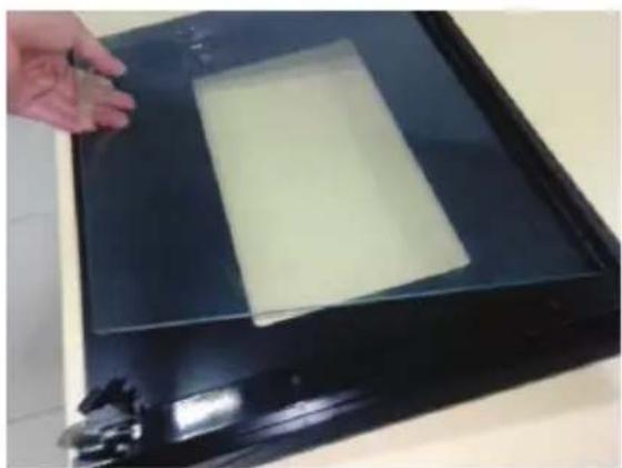
Step 3: Lift up the door outer glass and pull it out, then take the door middle glass out as the same way;

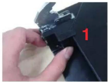
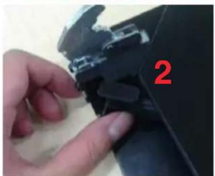
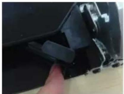
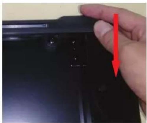
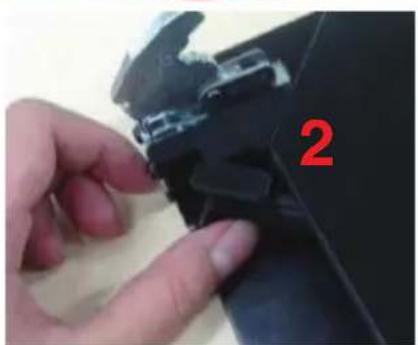
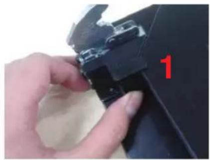
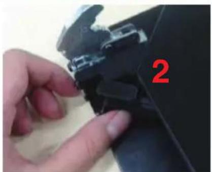
Step 4: Use one hand to push the door frame up cover toward middle part (1), then lift up the cover with the another hand (2);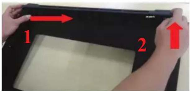
Step 5: See the screwdriver to disassemble the rotation bracket assemblies, then take out it from the door bracket;


Step 6: Change the new rotation bracket assemblies and insert it into the snap joints, then fix it with screw.
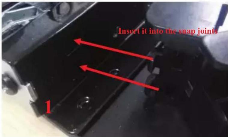

Step 7: Assemble the new door frame up cover on the bracket and make sure it be stable;
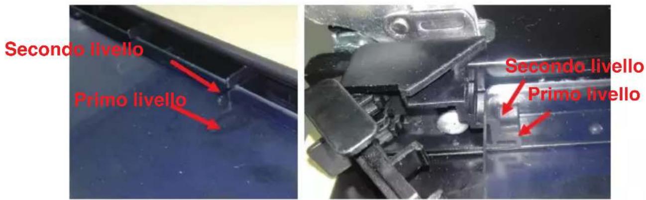
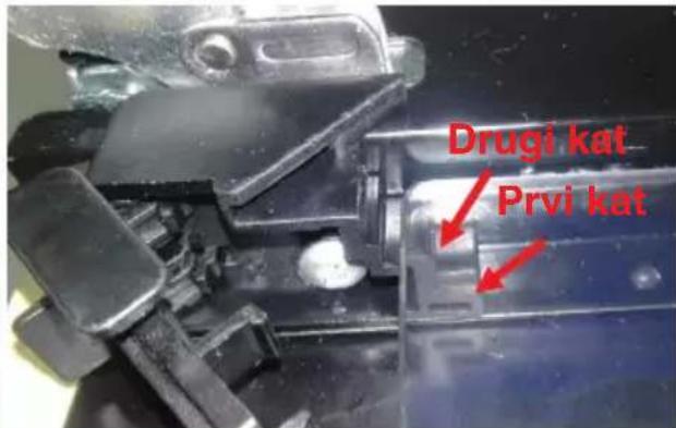
Step 8: Assemble the door middle glass and pay attention that it should be put at the second floor of door frame up covered for 3-layer glass door, and for 4-layer glass door, another middle glass should be placed at the first floor;


Step 9: Assemble the outer glass and accomplish the replacement work.


Hinge lock


DEAR CUSTOMER

WARNING REGARDING SHELF PLACEMENT:
REPLACING THE OVEN LAMP
ATTACHING THE OVEN TO THE CABINET
VENTILATION OPENINGS

Hinge lock


THANK YOU


Cable clamp
Lockable hinge


PREFACE


WARNING REGARDING SHELF PLACEMENT:
REPLACING THE OVEN LAMP
VENTILATION OPENINGS
Phillips screwdriver
Flathead
screwdriver
Pliers

Hinge lock




ACKNOWLEDGMENTS



Hinge lock


THANKS

WARNING ABOUT SHELF POSITION:
REPLACING THE BULB

VENTILATION OPENINGS
with Phillips tip
with flat
tip

Socket wrenches

Hinge
Step no. 3: Lift the door so that it is at a 30° angle relative to the front of the oven. Hold the door with one hand on each side. Lift and then pull the door.

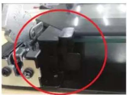
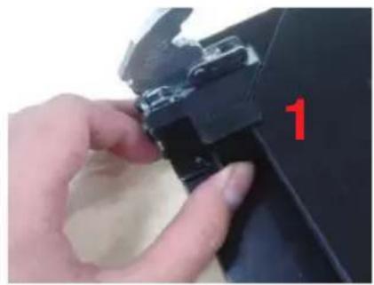
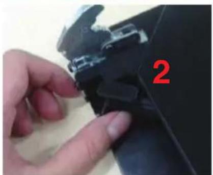


Step no. 4: With one hand, push the door frame cover towards the center (1), then lift the cover with the other hand (2);
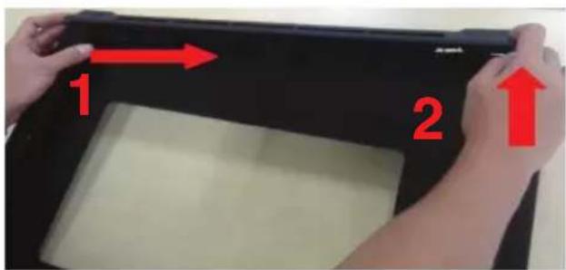
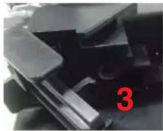

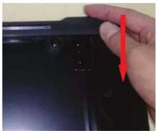
Step 8: Assemble the middle door glass and note that it should be placed on the second level of the door frame cover for triple-glazed doors, and for quadruple-glazed doors, an additional middle glass must be placed on the first level;

INTRODUCTION

WARNING FOR INSTALLING THE GRILLE:
REPLACING THE LIGHT BULB
SECURING THE OVEN INTO THE CABINET
VENTILATION SLOTS
Phillips screwdriver
Cable pliers
Diagonal pliers, adjustable wrench

Screwdriver
Disassembling parts

Hinge latch
- Step: close the door to an angle of 30° relative to the front of the oven.
Warning: do not pull the door forcefully to avoid breaking the glass.



Step 9: install the outer glass and complete the installation.
Service


- REPLACING THE OVEN LAMP
- VENTILATION OPENINGS
- ACKNOWLEDGMENT
- WARNING
- SAFETY HINTS
- FITTING THE OVEN INTO THE KITCHEN UNIT
- IMPORTANT
- DECLARATION OF COMPLIANCE
- OPERATION INSTRUCTIONS
- CLOCK SETTING
- FUNCTION SETTING
- NOTE
- LAMP SETTING
- INQUIRING FUNCTION
- CHILD LOCK FUNCTION
- REMINDER FUNCTION
- START/PAUSE/CANCEL FUNCTION
- ENERGY-SAVING FUNCTION
- RESERVATION FUNCTION
- ACCESSORIES
- SHELF PLACEMENT WARNING
- BULB REPLACEMENT
- SECURING THE OVEN TO THE CABINET
- VENTILATING OPENINGS
- INSTALLATION
- CLEANING AND MAINTENANCE
- INSTALLATION INSTRUCTION OF THE DOOR FRAME UP COVER AND ROTATION BRACKET ASSEMBLY
- DEAR CUSTOMER
- WARNING REGARDING SHELF PLACEMENT
- ATTACHING THE OVEN TO THE CABINET
- THANK YOU
- PREFACE
- ACKNOWLEDGMENTS
- THANKS
- WARNING ABOUT SHELF POSITION
- REPLACING THE BULB
- INTRODUCTION
- WARNING FOR INSTALLING THE GRILLE
- REPLACING THE LIGHT BULB
- SECURING THE OVEN INTO THE CABINET
- VENTILATION SLOTS
- SERVICE
Brand : BLAUPUNKT
Model : 5B30N 0250
Category : Oven