
WDT030 - Touch switch HAGER - Free user manual and instructions
Find the device manual for free WDT030 HAGER in PDF.
| Product type | KNX touch switch |
| Brand | Hager |
| Model | WDT030 |
| Display | 3.5-inch touch screen, 320 x 240 pixel resolution |
| Power supply | KNX bus (DC 21-32 V SELV) + auxiliary DC 24 V +/-10% SELV |
| Power consumption | Normal operation: approx. 0.9 W (brightness 50%); Standby: approx. 0.6 W |
| Dimensions (with decorative plate) | 95 x 93 x 44 mm (W x H x D) |
| Mounting depth | 18 mm |
| Weight | Not specified (estimated: approx. 150 g) |
| Protection rating | IP20 |
| Protection class | III |
| Operating temperature | 0 to 50 °C |
| Humidity | max. 95% non-condensing |
| Bus connection | KNX bus terminal (correct polarity required) |
| Auxiliary connection | DC 24 V terminal (non-polarized) |
| Digital/Analog Inputs | 4 inputs (pre-assembled) for temperature sensors or binary contacts |
| Integrated sensors | Proximity sensor, light sensor |
| Storage | micro SD card slot (for icons, images, screensaver) |
| Main functions | Lighting control, blinds, heating/air conditioning, display of values, alarm, timer, alarm clock |
| Customization | Up to 10 free pages, icon library, image import via micro SD |
| Security | Password protection per page, cleaning mode (touch lock 5 minutes) |
| Cleaning | Soft lint-free cloth, clear water if necessary; no harsh products |
| Warranty | According to applicable legal provisions |
| Accessories | Temperature sensor EK090, decorative plates WD11xx/WD12xx |
Frequently Asked Questions - WDT030 HAGER
User questions about WDT030 HAGER
0 question about this device. Answer the ones you know or ask your own.
Ask a new question about this device
Download the instructions for your Touch switch in PDF format for free! Find your manual WDT030 - HAGER and take your electronic device back in hand. On this page are published all the documents necessary for the use of your device. WDT030 by HAGER.
USER MANUAL WDT030 HAGER
Commande tactile KNX
Touch Control KNX
KNX Touch Control


Inhalt
natural_image
Simple geometric diagram of a square with a labeled point (1) on the side (no text or symbols within the shape)Bild 10: Montage
DE
DE

Bild 12: Demontage
5.2 Inbetriebnahme
1 Safety instructions....25
2 Design and layout of the device 25
3 Function....26
4 Operation....28
5 Information for electricians .... 40
5.1 Installation and electrical connection....40
5.2 Commissioning....43
6 Appendix....44
6.1 Technical data 44
6.2 Troubleshooting....45
6.3 Accessories 45
6.4 Warranty 45
KNX Touch Control
WDT030
Operating and assembly instructions
1 Safety instructions
Electrical equipment may only be installed and assembled by a qualified electrician. Always follow the relevant accident prevention regulations.
Failure to comply with these installation instructions may result in damage to the device, fire or other hazards.
When installing and laying cables, always comply with the applicable regulations and standards for SELV electrical circuits.
The device must not be coated with paint. Cover device during renovation work.
These instructions are an integral component of the product and must be retained by the end user.
2 Design and layout of the device
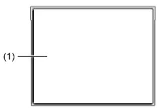
Figure 1: Front view
(1) Touch-sensitive display area
GB
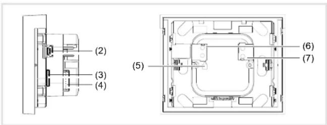
Figure 2: Side/rear view
(2) USB connection – only for programming in the factory
(3) Slot for micro SD card
(4) Jack for binary contacts or external temperature sensor - Digital/Analog IN
(5) Programming button and programming LED PRG
(6) KNX bus connection terminal
(7) Connecting terminal for auxiliary voltage - DC 24 V +/-10% SELV
Scope of delivery
- Display
- Supporting ring for installation on a wall box
- pre-assembled cable on a plug for Digital/Analog IN with conductor sleeves for the connection of external devices
- 4 Sticker for documentation of the physical address data
3 Function
System Information
This device is a product of KNX system and corresponds to the KNX guidelines. Detailed specialised knowledge obtained from KNX training courses is required for understanding. The planning, installation and commissioning are carried out with the help of KNX-certified software.
GB
system link start-up
The function of the device is software-dependent. The software is to be taken from the product database. You can find the latest version of the product database, technical descriptions as well as conversion and additional support programmes on our website.
Correct use
- Operating panel for switching functions, blind control, temperature and climate control
- Display/presentation of measured values
- Activation of alarm systems and display of security-related status
- Display device for texts, graphics, photos
- The device is only suitable for indoor areas
- Installation into wall box according to DIN 49073
Product characteristics
- high-resolution, touch-sensitive display
- up to 10 freely configurable pages for operating elements and displays
- integrated icon library for icons, self-generated icons importable with micro SD card
- up to 16 scenes configurable
- Timer functions
- Automatic functions for ventilation (window, ventilation units) and climate control (heating, cooling), blind (blinds, shutters, awnings) and light control
- Password protection per page
- internal proximity sensor for automatic activation of the display from standby mode
- integrated brightness sensor for automatic adjustment of the display lighting
- Connection for external temperature sensor (see accessories) and binary contacts

4 Operation
Display elements and operating concept
All display graphics are displayed in negative representation to reduce them to the most essential. In true representation, the backgrounds in the display are dark and the fonts/icons are white/light grey.
The complete display area is touch-sensitive. The device has a display page for standby operation in which time and date are displayed in the delivered state (Figure 3).
After connecting to the auxiliary voltage, the displays of the time and date are not current. A clock is required in the KNX installation for displaying the correct data.
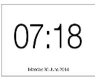
Figure 3: Standby display/screensaver
The display area is divided on the operating and display pages.
The top row of the display (8) is already preconfigured and at the first menu level next to basic data such as weekday, date and current time, displays the control surface ^2 for Settings following menu levels, this line shows you where you are currently located in the menu.
The bottom row of the display (10) has a total of 10 evenly divided control surfaces. From here, at the first menu level, individual, freely configurable pages can be opened, or at subsequent menu levels, defined standard functions can be triggered. The control surfaces for selecting pages are empty and can be filled individually with text. For navigating within a menu level, two additional functions / are available.
Between these two rows is the display and operating area (9) that can be freely configured using the ETS.

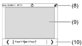
Figure 4: Layout of the display area
(8) top display row for basic displays and device settings
(9) Display and operating area – freely programmable
(10) bottom display row for page selection and defined default functions
Triggering a function, operating loads
Consumers, such as lighting, blinds, etc., are operated using the touch-sensitive control surfaces, and are dependent on the device programming.
Each touch on the touch-sensitive surface can be confirmed by an acoustic signal when the button sound ON is switched on.
If the device is in standby mode, touch anywhere on the touch-sensitive display area (1).
The last page/start page used is displayed.
If the proximity sensor in the menu Settings - Selective order the display switches automatically to the last page/start page used upon approaching.
■ Press a control surface in the display and functional area (9). The stored function is executed.
The actuation pulse lasts for the duration of the actuation. Depending on the function, short and long touches can trigger different actions, e.g. switching/dimming or roller shutter/blind.
If no action is executed on the display within an adjustable time period, the device returns automatically to standby display/to the screensaver – if this is activated.
Setting device
■ Press control surface in the top display row (8).
The display changes to the menu Settings.
Select submesystem
GB
GB
■ With go to the next/previous page, on which up to 4 setting parameters each can be selected.
Press control surface for the parameter required.
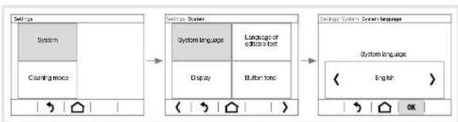
The display changes to another page where you must select once again, or it changes directly to the setting of the parameter (Figure 5).
■ WITH decrease/increase the parameter value, with >/ < scroll to a preset value (Figure 5) or with ON / OFF activate/deactivate the parameter (Table 1).
■ With confirm the entry.
The display returns to the previous menu level.
If the entries are not confirmed, with the display returns to the previous menu level without saving. Using the display returns to a page preset previously as Staith outgaving.
flowchart
graph LR
    A["Setup"] --> B["System"]
    B --> C["Cleaning mode"]
    C --> D["Configuration"]
    D --> E["System System"]
    E --> F["Display"]
    E --> G["Button tone"]
    F --> H["System Language"]
    H --> I["Language of edit a font"]
    I --> J["Configuration"]
    J --> K["System Language"]
    K --> L["English"]
    K --> M["OK"]
Figure 5: Example of setting the system language
| Parameters Actions Settings | ||
| System language | 〉/〈 | Deutsch, Italiano, Polish, Espanol, Nederland, English, Francais |
| Language of editable text | 〉/〈 | Deutsch, English, Francais, Espanol, Italiano, Nederland |
| Display-Brightness | 〉/〈- /〉/〈- / | Brightness control: via KNX bus OFF as per room brightness ^1 Start value: 1 ... 100 %Automatic switchoff: when ambience dim, ON, OFFActivate, if screen has not been touched for: 5 s ... 2 h (gradual) |
| Parameters Actions Settings | ||
| Display- Screen saver ^2) | ON/OFF-/YES/NO>/< | Activation after:5 s ... 2 h (gradual)Proximity sensor: Screen saver OFF on approachScreen saver mode: Screen OFF, Analog clock, Digital clock, picture from sd-card (- / for Picture no), Slide show |
| - Start page(after Reset,home button) | >/ < | one of the 10 configured pages for operating elements and displays can be defined as start page |
| -No-touchaction | ON/OFF | ON: Return to start page if no action has occurred for 5 min |
| Button tone | ON/OFF | ON: Each touch of a touch-sensitive control surface is acknowledged with a short acoustic signal. |
| Alarm | -/ON/OFFON/OFF-/ | Alarm Number ^3 : 1 ... 6Blinking backlightAlarm signalDisplayed symbol ^4 : 1, 2 ... - e.g. (▲) |
| Timer | see Setting timer | |
| Alarm clock | see Setting alarm | |
| Service | YESYESYESON/OFF---0 ... 9 | Reset access codeReturn to last ETS downloadReset - RestartKNX:KNX PROG-LED, Display of the physical addressInfα Display of the software versionsLicence: Reading of licence conditionsInternal sector: Entry of a code |
Even without confirmation the display brightness dims or brightens depending on the room brightness. After a further action, the brightness is reset to the confirmed mode.
21 Without any further action on the display the display with ON returns to screensaver, and with OFF returns to the defined start page.
^31 For meanings of the number codes, see the application description on the homepage.
Table 1: Settings in the System menu
GB
GB
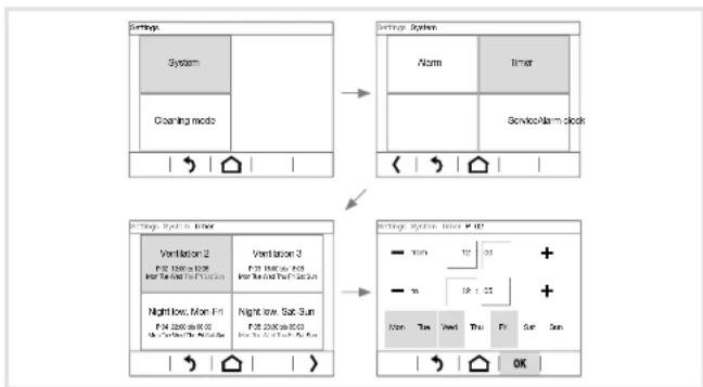
Setting timer (Figure 6)
In the Timer menu, up to 16 recurring time periods with an adjustable start time and end time can be changed. An automatic function is assigned to each time period, e.g. overnight shutdowns. Mo-Fr from 22:00 to 06:00 (Figure 6).
This time period can be assigned to one, two, ... all weekdays.
Time periods and the automatic functions to be executed during this time must be programmed in the ETS beforehand. The page in the Timer menu is empty when delivered.
At least one time period with a function is programmed.
■ Wihenter menu SettingseSystem
Timer
The display changes to the timer menu. The programmed time periods are displayed (Figure 6).
- Search and select the time period you wish to change using.
■ Press the display surface for hours, then the display surface for the minutes of the start time from in succession.
The display area of the activated value is framed by a light border at the bottom and to the right.
■ With change the respective setpoint.
In the same way, change the end titoe
■ Activate the button for each weekday on which this function should be executed within the defined time period.
The active buttons of the weekdays are displayed in light grey.
■ With confirm the entry.
The display returns to the previous menu level.
If the entries are not confirmed, with the display returns to the previous menu level without saving. Using the display returns to a page preset previously as Staithpageaving.
flowchart
graph TD
    A["Settings"] --> B["Settings System"]
    B --> C["Settings System, timer"]
    C --> D["Settings System, timer + OK"]
    A --> E["Systems"]
    E --> F["Cleaning mode"]
    F --> G["Verilacion 2"]
    G --> H["Nightlow, Mon Fri"]
    H --> I["Verilacion 3"]
    I --> J["Nightlow, Sun Sun"]
    J --> K["Verilacion 4"]
    K --> L["ServiceAlarm clock"]
Figure 6: Changing a time period
GB
GB
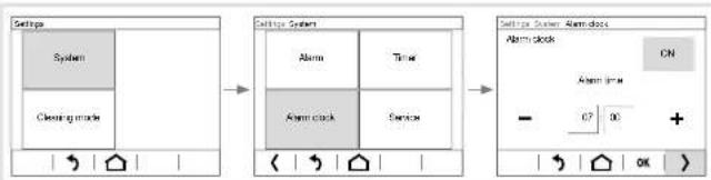
Setting the alarm (Figure 7)
■ Press the time display in the top display row (9).
Or:
■ Withenter the Settings and the System . Alarm clock
The display changes to the menu Alarm clock.
■ Press the display surface for hours, then the display surface for minutes in succession.
The display area of the activated value is framed by a light border at the bottom and to the right.
■ With decrease/increase the respective setpoint.
- With< go to the next/previous setting parameter, and in this way, set all parameters for the alarm time (Table 2).
■ With confirm the entry.
The display returns to the previous menu level.
If the entries are not confirmed, with the display returns to the previous menu level without saving. Using the display returns to a page preset previously as Shaith outgaving.
| Parameters Actions Settings | ||
| Alarm duration | >/< | until confirmation, after 5 s ... 2 h (gradual) |
| Repeat alarm in snooze mode | >/< | none, after 1 min, 2 min, ... |
| Acoustic alarm signal | ON / OFF | |
| Alarm screen flashing | ON / OFF | |
Table 2: Settings in the Alarm clock menu
flowchart
graph LR
    A["Settings"] --> B["Clearing mode"]
    B --> C["Alarm clock"]
    C --> D["Alarm clock"]
    D --> E["ON"]
    E --> F["OK"]
Figure7: Setting of the alarm time
Using individual pictures/graphics
A large library of graphics is available at the factory for designing operating and display pages for applications in light, blind and HVAC control technology as well as multimedia and safety technology, which is stored in the device.
Additionally, you can load your own graphics for icons or control knobs, pictures or picture sequences into the device. These have to be saved on a micro SD card at the topmost level in a defined resolution and specific file format.
When doing so, it is essential to use the predefined folder names (Table 3). Moreover, the image files must be named with a 4-digit numerical sequence - (0001 ... 9999) - in order to be retrievable in the ETS or in the display menu.
| Pictures/graphics for: | Resolution | File format | Folder name |
| Slideshow as screen-saver | 320 x 240 px | jpg (RGB colour space) | diashow |
| Single picture display as screensaver | 320 x 240 px | jpg (RGB colour space) | diafix |
| Still picture display ^1) | 320 x 240 px | jpg (RGB colour space) | festbilder |
| small icon ^1) | 48 x 48 px | png | icons |
| Control knob ^1) | 158 x 158 px | png | icons |
^11 only configurable over the ETS, not directly selectable on the screen
Table 3: My pictures/graphics on micro SD card
The device is connected, but not yet mounted, so that the slot for Micro SD Card (3) is accessible. The system has not yet started up. Pictures/graphics are stored on a micro SD card.
If the system already started up before inserting the micro SD card, in menu Settings- System execute a Reset The device is restarted.
■ Insert micro SD card into the slot (3) until it snaps into place. When doing so, make sure that the contacts of the card are facing up towards the display.
■ Switch on auxiliary voltage.
The device starts up.
In the display menu, an individual screen saver can be set with image data from the Micro SD Card.
■ Withenter menu Settings System select Screen saver
The display changes to the menu Screen saver.
- With < scroll in the bottom display row (10) to the setting parameter
Screen saver mode and select.
GB
With< select e.g. picture from sd-card
■ With change to selection of the Picture no.
■ With set the Pictanimage stored on the SD card.
Intrinsic icons for control surfaces are to be deposited on the memory card under image number 0250 ... 9999 and can be allocated in the ETS.
The configuration of images for permanent displays such as for a greeting screen is done in the ETS. With a still image display, the touch-sensitive display is locked for the length of the display.
The micro SD card must remain in the device while being used as My Pictures/Graphics.
GB
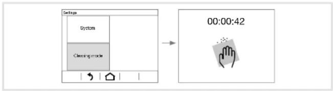
Cleaning display
The device has a special cleaning function to prevent any unintended functions from being activated when removing dirt or fingerprints etc. While the cleaning function is active, nothing is evaluated while the display surface is touched.
■ Press control surface in the top display row (8).
The display changes to the menu Settings.
■ Select submeCleaning mode (Figure 8).
The cleaning icon displays the locking of the touch-sensitive display. Touches are not evaluated – in the delivered state 5 minutes – for the configured period. The remaining cleaning time is displayed on the screen as a countdown (Figure 8).
- Clean the display surface with a lint-free cloth. Moisten the cleaning cloth slightly with clear water if necessary.
After the countdown has finished, the display returns to the screensaver/start page. The device can be operated again.
Do not use any sharp-edged implements for cleaning.
Do not use any aggressive detergents, acids or organic solvents.
Do not allow any moisture to get into the device.
flowchart
graph LR
    A["Settings"] --> B["Cleaning mode"]
    B --> C["00:00:42"]
Figure 8: Cleaning mode
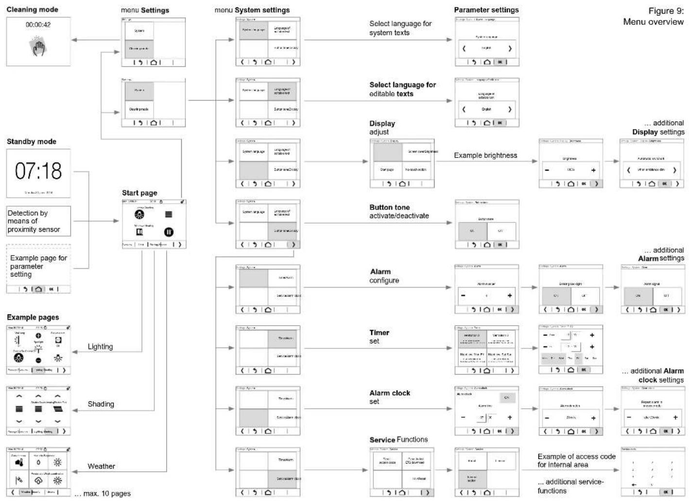
flowchart
graph TD
    A["Cleaning mode 00:00:42"] --> B["menu Settings"]
    B --> C["menu System settings"]
    C --> D["Select language for system texts"]
    D --> E["Parameter settings"]
    E --> F["Display adjust"]
    F --> G["Example brightness"]
    G --> H["... additional Display settings"]
    H --> I["Alarm configure"]
    I --> J["Timer set"]
    J --> K["Alarm clock set"]
    K --> L["Service Functions"]
    L --> M["Example of access code for internal area"]
    M --> N["... additional service-functions"]

    subgraph Start_page
        B --> C
        C --> D
        D --> E
        E --> F
        F --> G
        G --> H
        H --> I
    end

    subgraph Example_pages
        B --> C
        C --> D
        D --> E
        E --> F
        F --> G
        G --> H
        H --> I
        I --> J
        J --> K
        K --> L
        L --> M

    subgraph Example_page_for_parameter setting
        B --> C
        C --> D
        D --> E
        E --> F
        F --> G
        G --> H
        H --> I

    subgraph Example_pages
        B --> C
        C --> D
        D --> E
        E --> F
        F --> G
        G --> H
        H --> I

    end

    style Start_page fill:#f9f,stroke:#333
    style Example_pages fill:#ccf,stroke:#333
GB
GB
5 Information for electricians
5.1 Installation and electrical connection

DANGER!
Touching live parts in the installation environment can result in an electric shock.
The device could get damaged!
Disconnect the connecting cables before working on the device and cover all live parts in the area!
Selecting installation location
As a display and operating panel, the device should be mounted in a place that is easily accessible. The user habits are decisive when determining the installation height. We recommend an installation height of approx. 1.50m . Direct sunlight or powerful light sources could impair the proximity sensor.
Connecting and installing the device
Observe the layout requirements for SELV installations.
To avoid EMC interference, do not lay input cables parallel to mains cables.
■ Fasten the enclosed supporting ring (12) over the oblong-shaped holes onto at least 2 opposing screw domes of the wall box.
Alternatively, the supporting ring has 4 additional fixing holes for other mounting systems.
■ Guide the bus and auxiliary cable out of the wall box.
The second wire pair (yellow/white) of the KNX bus coupling unit may be used for connection of auxiliary voltage.
■ Connect the bus cable via the connecting terminal (6). Be sure that the polarity is correct.
■ Connect auxiliary voltage using a connecting terminal (7) independent of polarity.
After connecting the operating voltage, the device initialises itself for a few seconds. Message Loading KNX controller configuration appears. The device cannot receive any information via the KNX bus during this time.
If the device should also be used for temperature control, lay an external temperature sensor (see Accessories) in a ductwork and guide out the sensor head at the measurement point.
40
Do not install the temperature sensor near any sources of interference, e.g. electric stoves, refrigerators, draughts or sunshine. These influence the temperature measurement of the sensor.
Plug the enclosed pre-assembled cable into the jDigital/Analog IN (4).
■ Connect the external temperature sensor to the conductor sleeves of an input of this cable:
- Input 1: black GND/white
- Input 2: black GND/yellow
- Input 3: black GND/purple
- Input 4: black GND/blue
All black connecting wires GND are connected together internally.
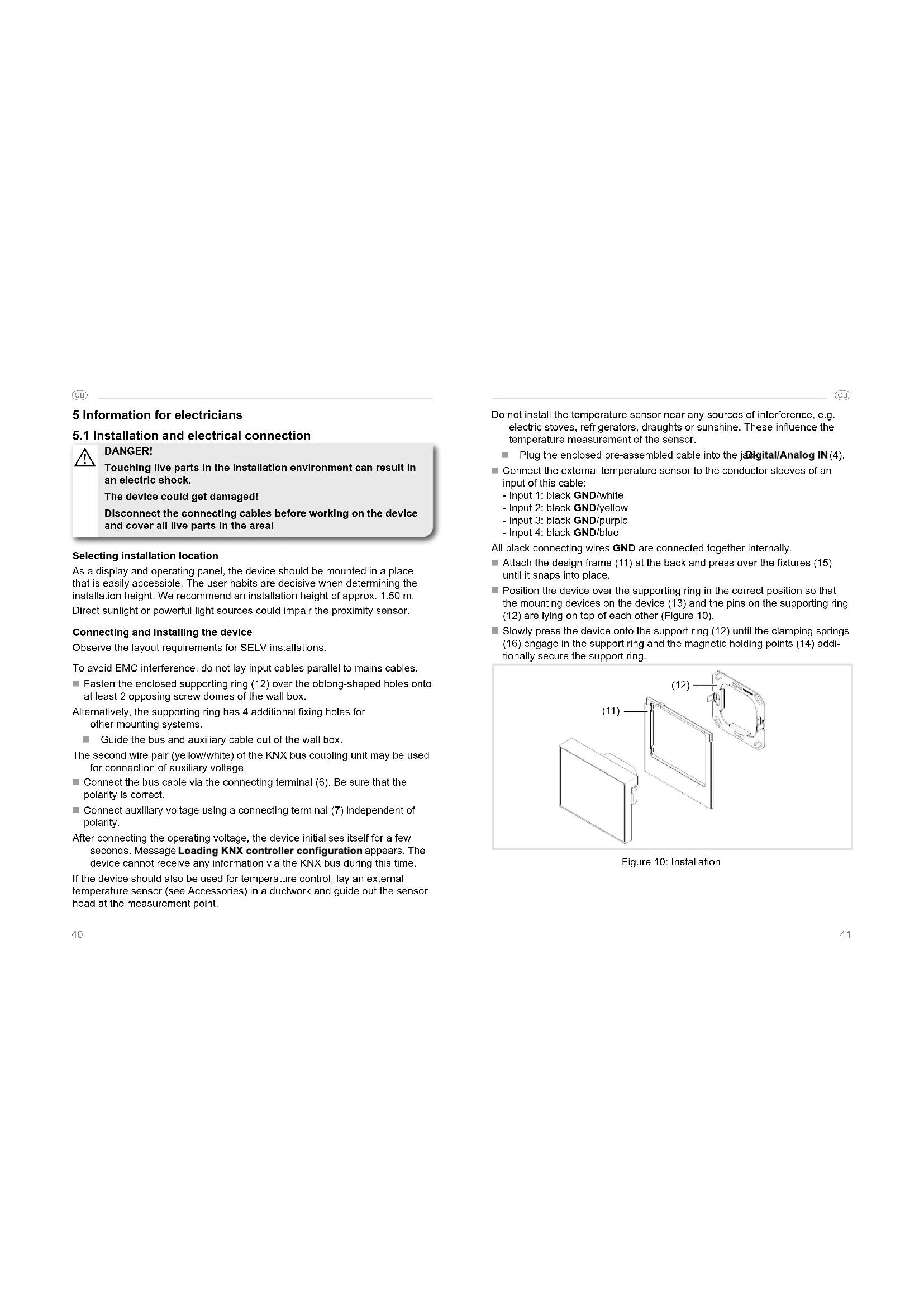
- Attach the design frame (11) at the back and press over the fixtures (15) until it snaps into place.
■ Position the device over the supporting ring in the correct position so that the mounting devices on the device (13) and the pins on the supporting ring (12) are lying on top of each other (Figure 10).
Slowly press the device onto the support ring (12) until the clamping springs (16) engage in the support ring and the magnetic holding points (14) additionally secure the support ring.
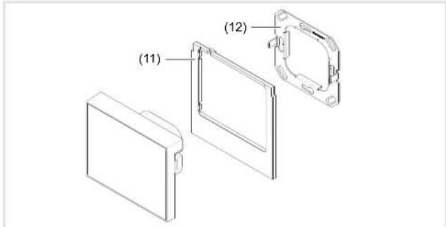
Figure 10: Installation
41
GB
GB
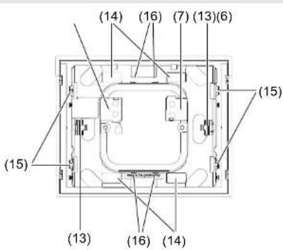
Figure 11: Rear view
(11) Design frame (not within scope of delivery)
(12) Supporting ring with pins
(13) Mounting devices for supporting ring
(14) magnetic holding points
(15) Fixtures for design frame
(16) Clamping springs
Dismantling the device
■ Pull device out of wall box (Figure 12).
The holding force of the clamping springs (16) must be overcome.
■ Press fixtures for the design frame (15) inwards slightly and remove the design frame.
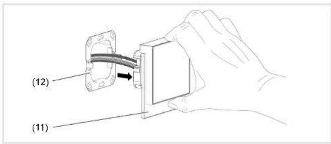
Figure 12: Dismantling
5.2 Commissioning
system link – Loading the physical address and application software
The device is connected to the KNX bus and auxiliary voltage.
The physical address is only ever assigned for one device. Only one device can ever be in programming mode.
■ Switch on bus voltage
■ Switch on auxiliary voltage.
■ Press programming but PRG (5) at the back of the device.
The programming LED PRG (5) lights up.
Or via the menu:
■ Press control surface in the top display row (8).
The display changes to the menu Settings.
■ Then selSystem - ServiceCKNXion.
■ Switch control surface KNX – PROG LED ON
The device is in programming mode.
- Load the physical address into the device.
The programming LED goes out. In the display, the message Connection to KNX controller interrupted appears briefly. The device is restarted automatically. - Load application software into the device.
■ Stick enclosed stickers on the back of the device and note down the physical address.
GB
GB
6 Appendix
6.1 Technical data
KNX Medium TP 1
Start-up mode system link
Current consumption KNX DC 21 ... 32 V SELV
Current consumption KNX 10 mA
Auxiliary voltage DC 24 V +/-10% SELV
Screen diagonal 3.5"
Resolution 320 x 240 pixels
Viewing angle:
- horizontal type - 75 ... + 75°
- vertical type - 55 ... + 75°
Connection mode KNX bus connecting terminal
Power consumption KNX:
- Normal operation approx. 0.9 W (at 50% screen brightness)
- standby mode approx. 0.6 W
Operating temperature 0 ... +50 °C
Storage/transport temperature -10 ... +50 °C
Humidity max. 95 % - no condensation
Degree of protection
IP20
Protection class
III
Dimensions (W x H x D)
95 x 75 x 44 mm
Assembling height on wall
18 mm
Dimension with design frame (W x H x D)
95 × 93 × 44 mm
Connection of external temperature sensor/binary contacts
- Connection mode
4 x analog/digital (pre-assembled)
- Conductor cross-section (flexible) with conductor sleeve
0.25 mm²
- Cable length
max. 10 m
Test mark
KNX, CE
Conformity
acc. EMV Directive 2004/108/EC
Standards
EN 50491-5-1:2010
EN 50491-5-2:2011
EN 50491-5 -3: 2011
6.2 Troubleshooting
Bus operation is not possible
Manufacturer's logo and message No connection to KNX controller are displayed.
Cause: Bus voltage is not present.
Check bus connection terminals for correct polarity.
Check bus voltage by activating/pressing the programming button PRG(5).
No indication in display
Cause: Auxiliary voltage is not present.
Check connection for auxiliary voltage (polarity independent).
Check auxiliary voltage by means of measuring device.
6.3 Accessories
Temperature sensor
EK090
Design frame
WD11xx, WD12xx
6.4 Warranty
We reserve the right to make technical and formal changes to the product in the interest of technical progress.
Our products are under guarantee within the scope of the statutory provisions. If you have a warranty claim, please contact the point of sale or ship the device postage free with a description of the fault to the appropriate regional representative.


Sommaire
Commande tactile KNX
WDT030
natural_image
Simple geometric diagram of a square with a labeled line (1) at the center (no text or symbols beyond the label)Figure 10 : montage

■ Pull device out of wall box (Figure 12).
Dimensions (I x H x P) 95 x 75 x 44 mm
natural_image
Simple geometric diagram of a square with a labeled line (1) at the center (no text or symbols within the shape)flowchart
graph LR
    A["Institutional"] --> B["Institutional Language"]
    B --> C["Institutional Language - Language selection"]
    C --> D["Institutional Language - Language selection"]
flowchart
graph LR
    A["Input Window"] --> B["Sistema"]
    A --> C["Modal in pulse"]
    B --> D["00:00:42"]
    C --> D
    D --> E["Arrow pointing to the timer icon"]
Dimensioni (L x A x P) 95 x 75 x 44 mm
natural_image
Simple geometric diagram of a square with a labeled line (1) at the center (no text or symbols within the shape)Afb. 10: montage


Afb. 12: demontage

- Inhalt
- Inbetriebnahme
- KNX Touch Control
- Safety instructions
- Design and layout of the device
- Scope of delivery
- Function
- System Information
- system link start-up
- Correct use
- Product characteristics
- Operation
- Display elements and operating concept
- Triggering a function, operating loads
- Setting device
- GB
- Setting timer (Figure 6)
- Setting the alarm (Figure 7)
- Using individual pictures/graphics
- Cleaning display
- Information for electricians
- Installation and electrical connection
- DANGER!
- Selecting installation location
- Connecting and installing the device
- Dismantling the device
- Commissioning
- Appendix
- Technical data
- Troubleshooting
- Bus operation is not possible
- No indication in display
- Accessories
- Warranty
- Sommaire
- Commande tactile KNX
Brand : HAGER
Model : WDT030
Category : Touch switch