AS-6030 - Window automation Protector - Free user manual and instructions
Find the device manual for free AS-6030 Protector in PDF.
User questions about AS-6030 Protector
0 question about this device. Answer the ones you know or ask your own.
Ask a new question about this device
Download the instructions for your Window automation in PDF format for free! Find your manual AS-6030 - Protector and take your electronic device back in hand. On this page are published all the documents necessary for the use of your device. AS-6030 by Protector.
USER MANUAL AS-6030 Protector
text_image
OK TIF ③ ⑤ANSCHLUSSBEISPIEL 2
text_image
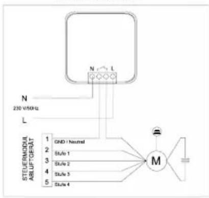
N 230 V/50Hz L STEUERMODUL ABLUF-GEFAT 1 2 3 4 5 GND / Neutral Stu/6 1 Stu/6 2 Stu/6 3 Stu/6 4 MSENDER FÜR FENSTER

text_image
6 PROTECTOR U U CE CTRM 7 U MARKET SENDER FEDERAL DUCTOR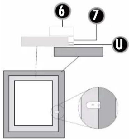
text_image
Diagram of a mechanical or optical setup with labeled components and a magnified view showing internal structure.


text_image
DEUTSCH | AS-6030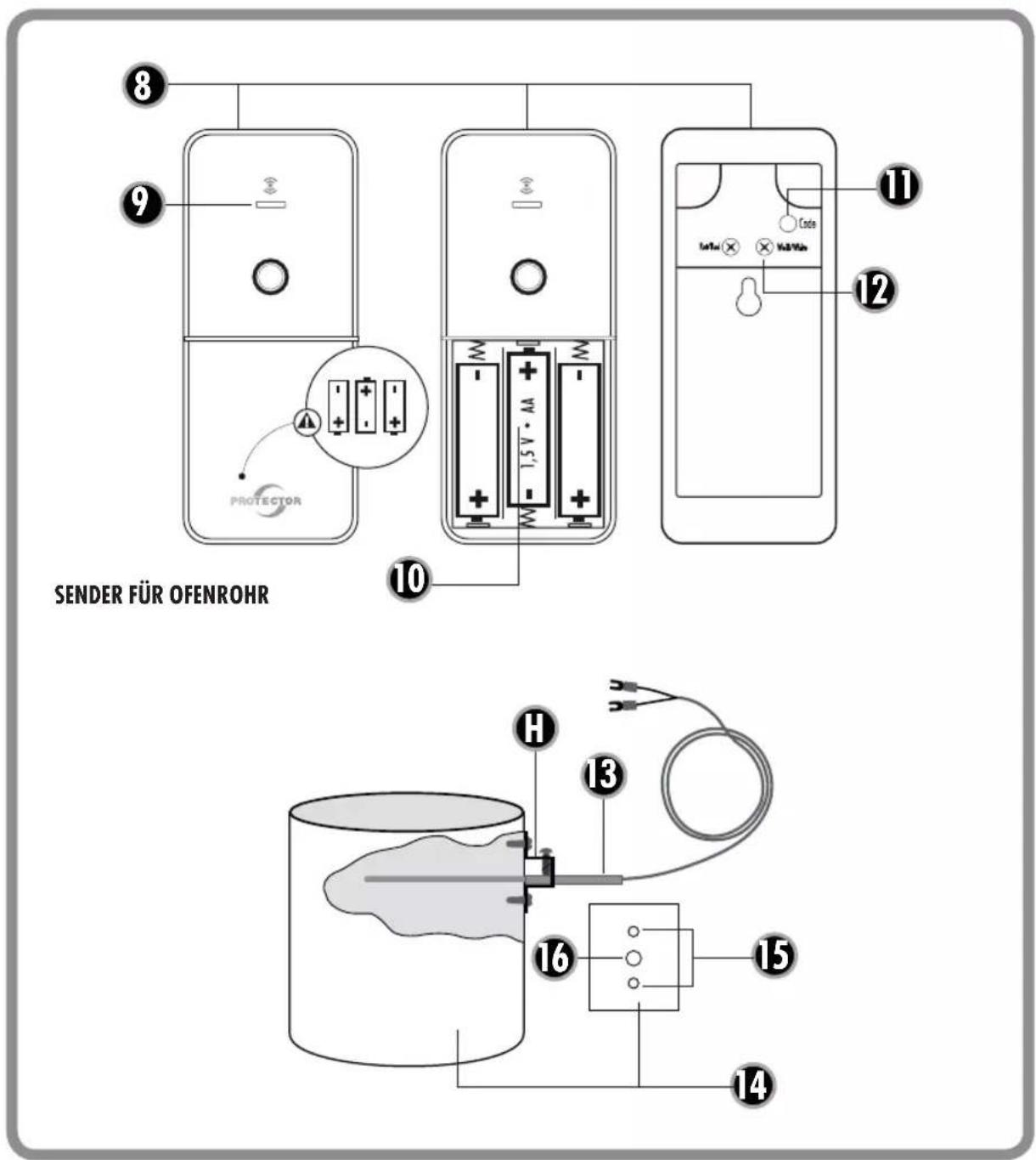
text_image
8 9 PROTECTOR 10 SENDER FÜR OFENROHR 11 Code 12 13 H 14 15 16text_image
N 200 V55Hz L N L PE2
text_image
③ ⑤EXAMPLE 2
text_image
N 250 WDR L GND BURER DTIS 1 BURER DTIS 2 BURER DTIS 3 BURER DTIS 4 MTRANSMITTER WINDOW
text_image
6 PROTECTOR 6.1 CE TRAM 7 U MAGNET SENDER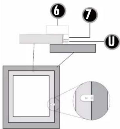
text_image
Diagram of a mechanical or electrical assembly with labeled components and a magnified view showing internal structure.

text_image
ENGLISH | AS-6030
text_image
8 9 10 TRANSMITTER 11 12 SERTEL 13 H 14 15 16 17 PROTECTORWIRELESS EXHAUST AIR CONTROL SYSTEM MODEL AS-6030
General
i Please read these instructions carefully before installing and operating the device to avoid installation or operating errors.
The wireless exhaust air control system AS-6030 is used in conjunction with exhaust air systems, such as an extractor hood in rooms with access to an open fire, for example with a gas-fuelled heater, an open fireplace, tiled stove, wood-burning stove, oil-burning stove etc.
When operating an exhaust air system, e.g. an extractor hood or exhaust fan, air is transported out of the room to the outside, which can cause negative pressure to form in the closed space.
The combustion of fuel in an open hearth creates odourless and invisible carbon dioxide and carbon monoxide gases. These gases can be sucked into the room from the hearth by way of an exhaust air system and lead to the fatal poisoning of anyone spending time in the room.
How the system works
Provided that the stove/exhaust pipe is cold (below 38^ C), the extractor hood connected to the receiver is supplied with power and functions as usual. If the temperature inside the exhaust pipe increases to a temperature above 38^ C, the receiver turns off the connected extractor hood. To turn it


on, open the window(s) with the window contact switch. After the exhaust pipe is cooled to below 38^ C again, the extractor hood can be used again without a window being opened.

CAUTION!
The shutters must be open when the extractor hood is in operation! If the shutters are closed, a sufficient fresh air supply cannot be guaranteed!
Key
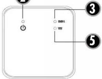
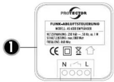
1 =Receiver
2 =Power LED
3 =Status LED
5 =Test button
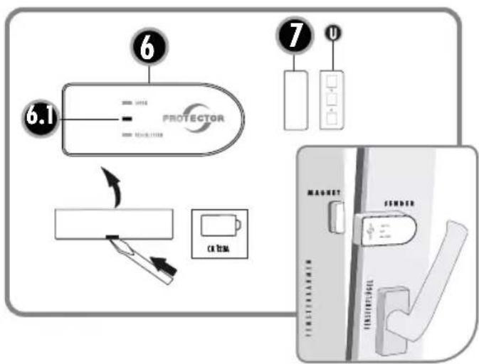
6 = Window contact
6.1 = Window contact transmitter LED
7 =Magnet
8 =Transmitter for the thermal sensor
9 =Thermal sensor transmitter LED
10 =Battery compartment
11 = Programming button
12 =Connection terminal for the thermal sensor
13 =Thermal sensor
14 = Exhaust gas pipe
15 = Through hole (4 mm)
16 =Mounting holes (2 mm)
H = Mounting bracket
U = Washers


ENGLISH | AS-6030
INSTALLATION
We recommend the system is installed by installation and heating engineers or electricians.
Professional installation ensures safe long-term operation. A functional test can be carried out by the district chimney sweep.
Assembly instructions for window contact (6)
Minimum window opening
These are based on:
a) The power of the exhaust air device in m ^3 /h
b) The size of the window to be opened in m^2
c) The size of the window opening in cm (see table 1)
Most kitchens have rectangular tilt and pivot windows. If your window is round for example, please ask the installation and heating engineers or electrician to calculate the minimum opening.
The minimum opening of rectangular windows is shown as an example in the table for the tilt and pivot position.
Calculation table to determine the minimum opening of your window
1) Determine the extraction power of your exhaust air extraction device unit in m³/h. You can find the exhaust air extraction power on the identification plate or in the operating instructions of your exhaust air device (e.g. extractor hood).
2) Measure the inner width and height of the window and calculate the window size in m^2 .
(width x height = m ^2 ; e.g. 0.8 m x 1.0 m = 0.8 m ^2 ) = window size
Table 1
| Window area in m^2 | ||||||||||||||||
| in m^2 | 0,2 | 0,3 | 0,4 | 0,5 | 0,6 | 0,7 | 0,8 | 0,9 | 1 | 1,1 | 1,2 | 1,3 | 1,4 | 1,5 | ||
| in cm^2 | 2000 | 3000 | 4000 | 5000 | 6000 | 7000 | 8000 | 9000 | 10000 | 11000 | 12000 | 13000 | 14000 | 15000 | ||
| Gap opening measurement in cm | Maximum permissible exhaust air performance in m^3/h | |||||||||||||||
| 5 | 199 | 252 | 297 | 337 | 373 | 406 | 437 | 466 | 493 | 519 | 544 | 568 | 591 | 613 | ||
| 6 | 246 | 311 | 365 | 413 | 456 | 495 | 532 | 567 | 600 | 631 | 661 | 690 | 717 | 744 | ||
| 7 | 294 | 369 | 432 | 488 | 538 | 585 | 628 | 668 | 707 | 743 | 778 | 811 | 843 | 874 | ||
| 8 | 342 | 427 | 500 | 563 | 621 | 674 | 723 | 770 | 813 | 855 | 895 | 933 | 970 | 1005 | ||
| 9 | 389 | 486 | 567 | 639 | 704 | 763 | 819 | 871 | 920 | 967 | 1012 | 1055 | 1096 | 1136 | ||
| 10 | 437 | 544 | 635 | 714 | 786 | 852 | 914 | 972 | 1027 | 1079 | 1128 | 1176 | 1222 | 1266 | ||
| 11 | 485 | 603 | 702 | 790 | 869 | 942 | 1009 | 1073 | 1133 | 1191 | 1245 | 1298 | 1348 | 1397 | ||
| 12 | 532 | 661 | 770 | 865 | 951 | 1031 | 1105 | 1174 | 1240 | 1302 | 1362 | 1419 | 1475 | 1528 | ||
AS-6030 | ENGLISH
3) Using the table, work out the opening size (minimum opening for your window) from the extraction power and window size.
4) While the window is in the titled position, measure the upper inner gap size of the window in cm. The gap size of your window must not be below the opening size calculated! The bigger the gap or window opening, the better.
5) If the gap size of the window is less than the permissible value for the opening size according to the table, the window may only be able to achieve the required opening size in the pivot position. There must also be a minimum gap when the window is in the pivoted position. The window contact shall be positioned in such a way as to ensure the minimum gap size. We recommend you ensure the minimum gap size using a spacer.
Preparation
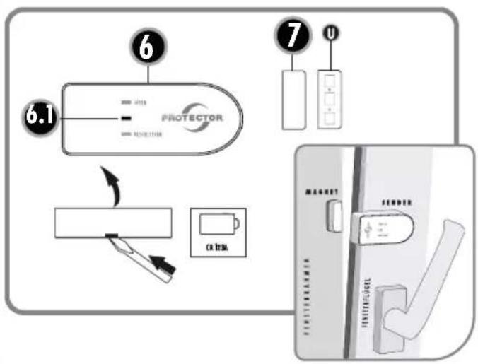
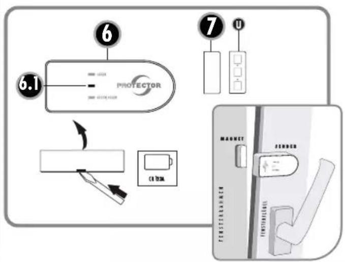
Install the transmitter (6) and magnet (7) to the window frame and the window casement in such a way that the distance from the magnet and transmitter is less than 7 mm on all sides when the window is closed. To adjust this, use the washers supplied (U).
We recommend that you mount the transmitter and magnet using double-sided tape until it is ultimately secured in place and only screw everything when installation is complete.
Installation for tilted position
The transmitter and magnet must be mounted on the hinge side of the window. This means on the right for a right-hinged window and on the left for a left-hinged window.


The mounting point should be selected so that the „open window“ signal is only given if the necessary opening size is reached in accordance with the table. When pivoting the window, the magnet must always be less than 7 mm from the transmitter so that the transmitter always recognises the window as being closed! You should however make sure that the transmitter and magnet cannot touch when the window is pivoted.
Installation for pivoted position
The sensor and magnet must be mounted on the side where the tilt hinge is (usually below). The mounting point should be selected so that the "open window" signal is only given if the necessary opening size is reached in accordance with the table. When tilting the window, the magnet must always be less than 7 mm from the transmitter so that the transmitter always recognises the window as being closed! You should however make sure that the transmitter and magnet cannot touch when the window is tilted.
1) Fix the magnet in place at the designated location using the double-sided adhesive pad supplied.
2) Fix the window contact onto the window with the double-sided adhesive pad supplied.

WARNING: The distance between the transmitter and the magnet must not exceed 7 mm!
3) Once all functions have been tested successfully, the transmitter and magnet must be screwed to the window/window frame. For this purpose, there is a hole prepared in the battery compartment of the transmitter and in the lower part of the magnet housing. The transmitter and magnet can therefore be screwed to the window/window frame. This prevents the transmitter and magnet from accidentally falling off!


Functional test when the window is tilted or pivoted
- Slowly bring the window into the tilted or pivoted position, the transmitter LED (6.1) on the transmitter will briefly light up green before the maximum tilted or pivoted position is reached.
- If you close the window, the transmission LED (6.1) will light up red.
- Finally, check the openings once more based on the minimum gap determined in table 1.

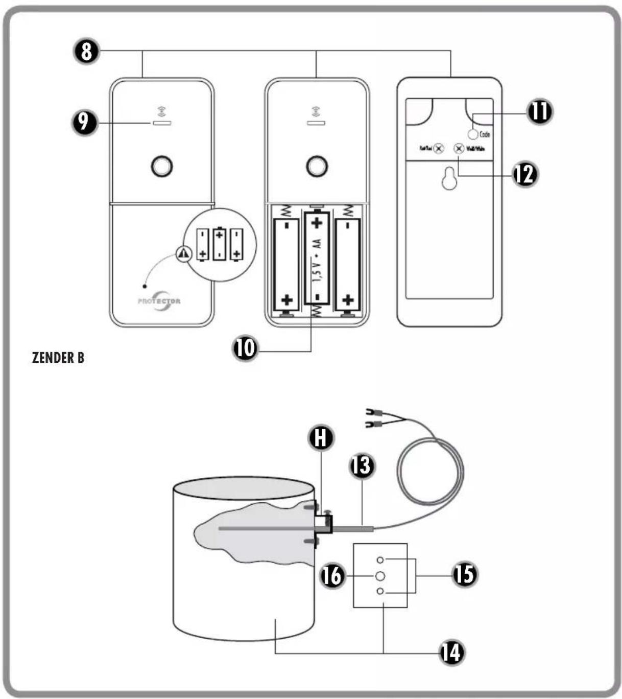
Installation instructions for the thermal sensor (13)
Note: To avoid burns to your skin, the stove should be off and allowed to cool!
The thermal sensor is passed through a hole in the exhaust gas pipe of your oven and screwed to the stove pipe using a mounting bracket. The transmitter should not be obscured by a covering as this could impair the wireless signals and shorten the range.
1) Drill a 4 mm hole for the thermal sensor at an appropriate point in the exhaust pipe of your stove. Make sure that the hole is positioned so that the thermal sensor is barely visible after installation.
2) Slide the mounting bracket over the thermal sensor; do not yet tighten the screw to fix the thermal sensor in place.
3) Insert the thermal sensor into the respective hole drilled in the exhaust gas pipe and slide it in until it stops.
4) Move the mounting bracket on the thermal sensor until it lies on the exhaust gas pipe, mark the two mounting holes of the bracket with a suitable pen, then pull the thermal sensor and the bracket back out of the exhaust pipe.
5) Drill holes measuring 2 mm in diameter at two previously marked mounting holes on the exhaust gas pipe.

Note: If the exhaust gas pipe is double walled, be careful to drill only through the outer pipe!
6) Attach the mounting bracket to the exhaust gas pipe by screwing the two self-tapping screws supplied and into two newly drilled holes.
7) Now run the thermal sensor through the mounting bracket until it stops and fix it in place at the bracket with the screw at the side. Do not pull it too tightly, as this would damage the thermal sensor.
8) Lay the thermal sensor cable to the transmitter module of the thermal sensor.
9) Connect the thermal sensor cable to the transmitter module, the red marked cable to the screw ,Rot/Red', and the white marked cable to the screw ,Weiß/White'.
10) There is a wall mount on the back of the transmitter module. This can be pushed down and removed from the transmitter.
11) Find a suitable location for mounting the transmitter and screw the wall mount of the transmitter to the mounting location. The transmitter module should be located at least 50 cm from the exhaust gas pipe to prevent the heat destroying the transmitter module. The transmitter should not be mounted behind a covering because this can limit the range.
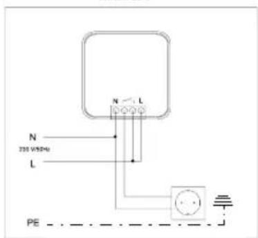
Installation of the receiver

The installation must be carried out by a qualified electrician. Warning! Only use the device in a building.
Connection example 1:
The receiver can be installed surface or flush-mounted in a distribution box, switch box or power socket with a min. diameter of 60 mm. The fastening clips can be broken off if necessary.
AS-6030 | ENGLISH
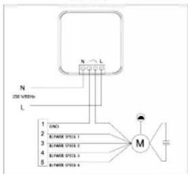
Connection example 2:
In exhaust air units with blowing speed controls, the receiver is connected in series to the fan motor supply to enable the lighting to function independently of the status of the receiver. If applicable, the fan motor cable must be led from the extractor hood housing if the housing overly shields the transmitter signal and the range is insufficient.
Note: The receiver should not be mounted behind a metal covering because this can limit the range.
OPERATION
Programming
When operating the device for the first time, it must be programmed. To do this, proceed as follows:
i Note: Please first program the window contact(s) and then the thermal sensor.
Window contact
1) Power the receiver (1).
2) Press and hold the test button (5) on the receiver until the LED (3) lights orange continuously. Release the test button.
3) Insert the CR 123A battery into the window contact (observe correct polarity) and hold the magnet to the window contact. The LED (6.1) on the window contact and the LED (3, red) on the receiver should flash briefly.
4) Complete the programming process by briefly pressing the test button of the receiver once.
Once the magnet is over 7 mm from the window


contact, the receiver should provide the connected device with electricity. If the magnet is then brought back closer to the window contact, power is shut off to the device again. If this does not happen, repeat the procedure.

Note: Up to three window contacts can be programmed at one receiver. In this case, the window contacts are co-dependent, i.e., each transmitter must receive the „open window" status before the receiver turns on the power. This is useful, for example, if there is a conservatory behind the window being monitored or if you want to use the tilt and pivot function.
Carry out steps one to 4 for each additional window contact.
Thermal sensor
1) Remove the batteries from the transmitter module (8) if they have already been inserted.
2) Power the receiver.
3) Press and hold the test button (5) on the receiver until the LED (3) lights orange continuously. Release the test button.
4) Now put the batteries back in the transmitter module, paying attention to the polarity of the batteries.
5) The LED (3, green) will blink once.
6) Briefly press the test button once to leave programming mode.
7) Now wait approx. five minutes, or press the programming button (11) on the transmitter for approx. two seconds.
Now the device is ready.


ENGLISH | AS-6030
Delete programming/factory settings
If anything went wrong during the programming or a transmitter needs to be replaced, the receiver must first be reset. To do this, hold down the test button (5) on the receiver for approx. six seconds. After approx. two seconds, the red LED (3) lights up; it then flashes briefly four seconds later. The test button can then be released and the receiver is returned to the original state, i.e. all transmitters must be reprogrammed.
Test function
Using the test button on the receiver, you can test the function of the relay in the receiver. If the test button is pressed briefly, the relay turns on for approx. one second (click-click). This function is only available when the window is closed and the stove in operation.
CE Notes
Strong electric, magnetic or high-frequency fields (discharge, mobile phones, wireless systems, mobile phones, microwaves) may cause the device(s) to malfunction.
CE Compliance
We confirm the conformity of the devices according to the European Directive 2004/108/EC on electromagnetic compatibility and the Low Voltage Directive 2006/95/EC. The radio approval is certified according to the EC R & TTE Directive 1999/5/EC.
Technical data
Mains voltage (receiver) 230 V \~, 50/60 Hz, approx. 2W
Breaking capacity 1000 W, 4.3 A, at cos phi = 1
Radio range up to 20 m
Radio frequency 868 MHz
Protection class IP 20, for dry rooms only
Battery (window contact) 1 x type CR 123A
Batteries (transmitter 3 x size AA /Mignon/LR6
module thermal sensor) alkaline
Technical changes may be made at short notice without advance warning as part of our product updates and device optimisation.
SAFETY NOTES
The warranty will be null and void in case of damages arising from violations of these operating instructions. We are not liable for consequential damages!
We accept no liability for material damages or injuries arising from inappropriate use or violation of the safety instructions. In such cases all warranty claims are null and void!
Do not use this product in hospitals or other medical facilities. Although this device transmits only relatively weak radio signals, the signals may in such locations result in malfunctioning of systems critical to life. The same may apply to other areas.
For reasons of safety and licensing (CE), unauthorised conversion and /or modification of the product is prohibited.
AS-6030 | ENGLISH

Do not take the product apart! There is a danger of lethal electric shock!
Do not leave packaging material lying about since plastic foils and pockets and polystyrene parts etc. could be lethal toys for children.
The device is suitable only for dry interior rooms (not bathrooms and other moist places). Do not allow the device to get moist or wet. There is a danger of lethal electric shock!
In industrial institutions, the accident prevention regulations of the Association of Commercial Professional Associations for electrical installations and equipment must be observed. Please consult a specialist should you have doubts regarding the method of operation, the safety, or the connections of the device.
Handle the product with care – it is sensitive to bumps, knocks or falls even from low heights.
2 YEAR LIMITED GUARANTEE
For two years after the date of purchase, the defect-free condition of the product model and its materials is guaranteed. This guarantee is only valid when the device is used as intended and is subject to regular maintenance checks. The scope of this guarantee is limited to the repair or reinstallation of any part of the device, and is only valid if no unauthorised modifications or attempted repairs have been undertaken. Customer statutory rights are not affected by this guarantee.


Please note!
No claim can be made under guarantee in the following circumstances:
- Operational malfunction
• Empty batteries or faulty accumulator - Erroneous coding/channel selection
- Fault through other radio installation (i.e. mobile operation)
• Unauthorised modifications / actions - Mechanical damage
- Moisture damage
• No proof of guarantee (purchase receipt)
Claims under warranty will be invalidated in the event of damage caused by non-compliance with the operating instructions. We do not accept any responsibility for consequential damage! No liability will be accepted for material damage or personal injury caused by inappropriate operation or failure to observe the safety instructions. In such cases, the guarantee will be rendered void.

Liability limitation
The manufacturer is not liable for loss or damage of any kind including incidental or consequential damage which is the direct or indirect result of a fault to this product.
GB
These operating instruction are published by Protector GmbH, An den Kolonaten 37, 26160 Bad Zwischenahn/Germany
The operating instructions reflect the current technical specifications at time of print. We reserve the right to change the technical or physical specifications.

natural_image
Gray gradient bar with no text or symbols, ranging from black to white (no text or symbols)


AS-6030
FRANÇAIS


RÉCEPTEUR
text_image
PROTECTOR FUNK-ABLÜFTSTEUERUNG MODEL: AS KIDR EMPRAAGER NETZENKÄNUNG: 250 Vat. — 50 Hz, or. 1 W SCHLTDLENTUNG: max. 1000 Vat. FREQUENCY: 450 MHz CE N LEXAMPLE 1

text_image
② ③ ⑤EXAMPLE 2
text_image
N 331 VSP4 L N L PE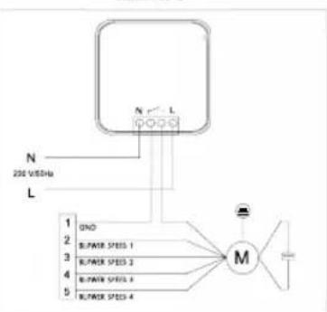
flowchart
graph TD
    A["200 VIDE"] --> B["N"]
    A --> C["L"]
    B --> D["M"]
    C --> D
    D --> E["Ground"]
ÉMETTEUR A
text_image
6 PROTECTOR 6.1 U 7 U CE TRAM MARKET FENDER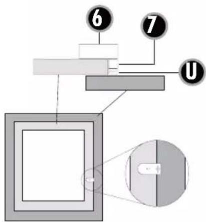
text_image
Diagram of a mechanical or optical setup with labeled components and an inset close-up view


text_image
FRANÇAIS | AS-6030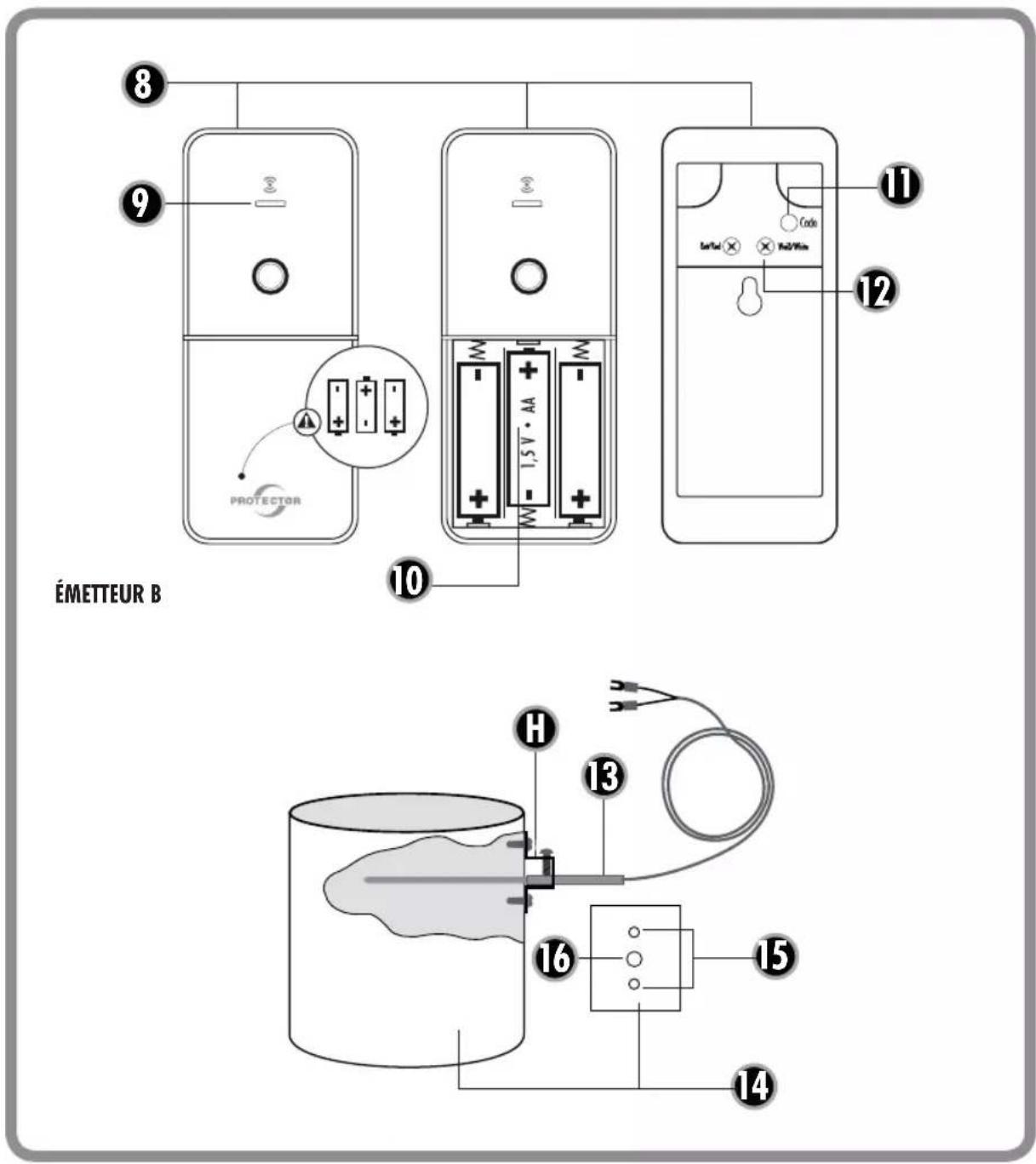
text_image
ÉMETTEUR B 8 9 PROTECTOR 10 11 Code 12 13 H 14 15 16AS-6030 | FRANÇAIS
COMMANDE D'ÉVACUATION D'AIR RADIO MODÈLE AS-6030
Généralités
text_image
N 230 V/50Hz L PE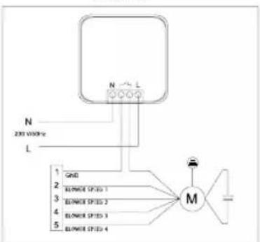
flowchart
graph TD
    A["200 VDDHz"] --> B["N"]
    B --> C["L"]
    C --> D["M"]
    D --> E["BLONER (STED 1)"]
    D --> F["BLONER (STED 2)"]
    D --> G["BLONER (STED 3)"]
    D --> H["BLONER (STED 4)"]
ZENDER A
text_image
6 PROTECTOR 6.1 U 7 CE CTRM MAGNET JEDDER TENSTEELARATH
text_image
Diagram of a mechanical or optical setup with labeled components and a magnified view showing a device.


NEDERLANDS | AS-6030
text_image
ZENDER B 8 9 10 11 12 Protector 1,5 V·Aa 13 H 14 15 16DRAADLOZE AFZUIGSYSTEEM-BESTURING MODEL AS-6030
Algemeen
natural_image
Gray gradient bar with no text or symbols, ranging from black to white (no text or symbols)


natural_image
Gray gradient bar with no text or symbols, ranging from black to white (no text or symbols)