X99 Extreme4 - Motherboard ASROCK - Free user manual and instructions
Find the device manual for free X99 Extreme4 ASROCK in PDF.

User questions about X99 Extreme4 ASROCK
0 question about this device. Answer the ones you know or ask your own.
Ask a new question about this device
Download the instructions for your Motherboard in PDF format for free! Find your manual X99 Extreme4 - ASROCK and take your electronic device back in hand. On this page are published all the documents necessary for the use of your device. X99 Extreme4 by ASROCK.
USER MANUAL X99 Extreme4 ASROCK
Copyright©2015 ASRock INC. All rights reserved.
Copyright Notice:
No part of this documentation may be reproduced, transcribed, transmitted, or translated in any language, in any form or by any means, except duplication of documentation by the purchaser for backup purpose, without written consent of ASRock Inc.
Products and corporate names appearing in this documentation may or may not be registered trademarks or copyrights of their respective companies, and are used only for identification or explanation and to the owners' benefit, without intent to infringe.
Disclaimer:
Specifications and information contained in this documentation are furnished for informational use only and subject to change without notice, and should not be constructed as a commitment by ASRock. ASRock assumes no responsibility for any errors or omissions that may appear in this documentation.
With respect to the contents of this documentation, ASRock does not provide warranty of any kind, either expressed or implied, including but not limited to the implied warranties or conditions of merchantability or fitness for a particular purpose.
In no event shall ASRock, its directors, officers, employees, or agents be liable for any indirect, special, incidental, or consequential damages (including damages for loss of profits, loss of business, loss of data, interruption of business and the like), even if ASRock has been advised of the possibility of such damages arising from any defect or error in the documentation or product.

This device complies with Part 15 of the FCC Rules. Operation is subject to the following two conditions:
(1) this device may not cause harmful interference, and
(2) this device must accept any interference received, including interference that may cause undesired operation.
CALIFORNIA, USA ONLY
The Lithium battery adopted on this motherboard contains Perchlorate, a toxic substance controlled in Perchlorate Best Management Practices (BMP) regulations passed by the California Legislature. When you discard the Lithium battery in California, USA, please follow the related regulations in advance.
"Perchlorate Material-special handling may apply, see www.dtsc.ca.gov/hazardouswaste/perchlorate"
ASRock Website: http://www.asrock.com

Manufactured under license under U.S. Patent Nos: 5,956,674; 5,974,380; 6,487,535; 7,003,467 & other U.S. and worldwide patents issued & pending. DTS, the Symbol, & DTS and the Symbol together is a registered trademark & DTS Connect, DTS Interactive, DTS Neo:PC are trademarks of DTS, Inc. Product includes software.
© DTS, Inc., All Rights Reserved.

Connect

Interactive

Neo:PC
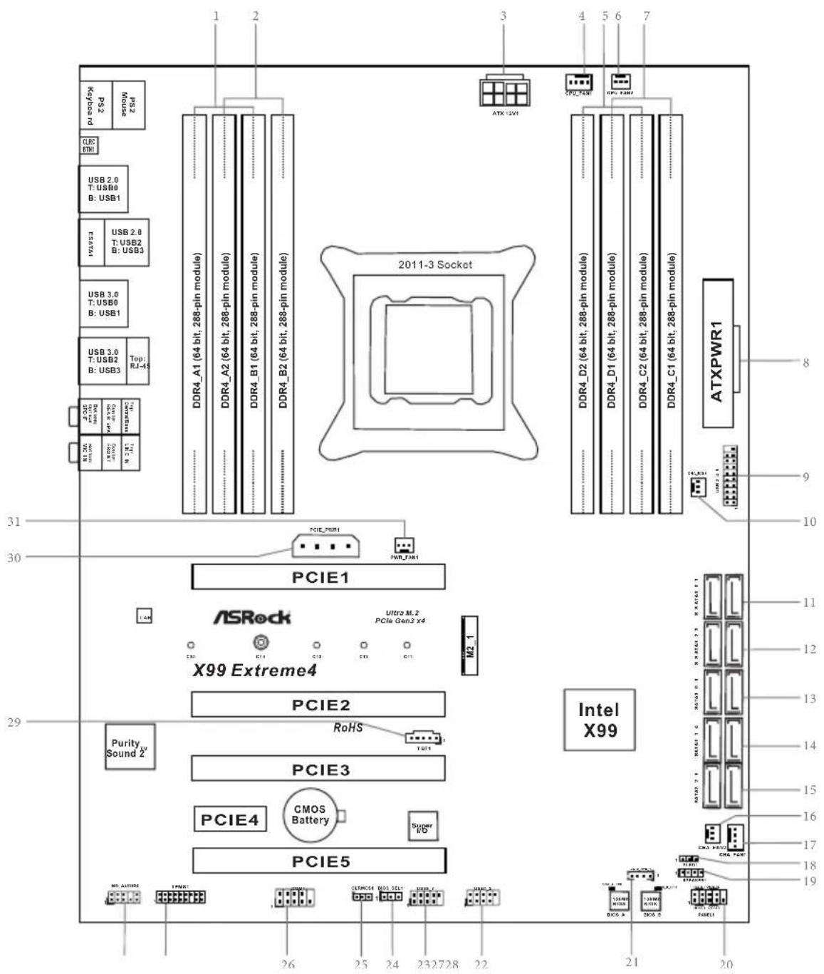
Motherboard Layout
text_image
Purity Sound 2 PCIE4 CMOS Battery PCIE3 RoHS PCIE2 X99 Extreme4 PCIE1 PCIE5 Super M2_1 ASRock PCIE1 PCIE4 PCIE3 PCIE2 Ultra M.2 PCIe GM13 X4 29 30 31 1 2 3 4 5 6 7 8 9 ATXPWR1 DDR4_A1 (64 bit, 288-pin module) DDR4_A2 (64 bit, 288-pin module) DDR4_B1 (64 bit, 288-pin module) DDR4_B2 (64 bit, 288-pin module) DDR4_D2 (64 bit, 288-pin module) DDR4_D1 (64 bit, 288-pin module) DDR4_C2 (64 bit, 288-pin module) DDR4_C1 (64 bit, 288-pin module) PS2 mouse Kojoa rod M1.300 USB 3.0 T-USB2 B: USB3 USB 3.0 T-USB0 B: USB1 USB 2.0 T-USB2 B: USB3 ESATRI USB 2.0 T-USB0 B: USB1 USB 2.0 T-USB0 B: USB1 PS2 mouseNo. Description
| 1 2 x 288-pin DDR4 DIMM Slots (DDR4_A1, DDR4_B1) |
| 2 2 x 288-pin DDR4 DIMM Slots (DDR4_A2, DDR4_B2) |
| 3 ATX 12V Power Connector (ATX12V1) |
| 4 CPU Fan Connector (CPU_FAN1) |
| 5 2 x 288-pin DDR4 DIMM Slots (DDR4_D2, DDR4_C2) |
| 6 CPU Fan Connector (CPU_FAN2) |
| 7 2 x 288-pin DDR4 DIMM Slots (DDR4_D1, DDR4_C1) |
| 8 ATX Power Connector (ATXPWR1) |
| 9 USB 3.0 Header (USB3_4_5) |
| 10 Chassis Fan Connector (CHA_FAN3) |
| 11 SATA3 Connectors (S_SATA3_0_1) |
| 12 SATA3 Connectors (S_SATA3_2_3) |
| 13 SATA3 Connectors (SATA3_0_3) |
| 14 SATA3 Connectors (SATA3_1_4) |
| 15 SATA3 Connectors (SATA3_2_5) |
| 16 Chassis Fan Connector (CHA_FAN2) |
| 17 Chassis Fan Connector (CHA_FAN1) |
| 18 Power LED Header (PLED1) |
| 19 Chassis Speaker Header (SPEAKER1) |
| 20 System Panel Header (PANEL1) |
| 21 HDD Saver Connector (SATA_PWR_1) |
| 22 USB 2.0 Header (USB4_5) |
| 23 USB 2.0 Header (USB6_7) |
| 24 BIOS Selection Jumper (BIOS_SEL1) |
| 25 Clear CMOS Jumper (CLRCMOS1) |
| 26 COM Port Header (COM1) |
| 27 TPM Header (TPMS1) |
| 28 Front Panel Audio Header (HD_AUDIO1) |
| 29 Thunderbolt AIC Connector (TBT1) |
| 30 PCIe Power Connector (PCIE_PWR1) |
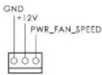
| 31 Power Fan Connector (PWR_FAN1) |
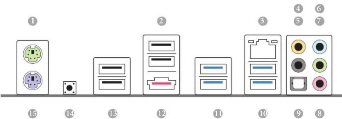
I/O Panel
text_image
Diagram showing 15 labeled electronic components or connectors with corresponding icons and numbers, likely representing a system or device layout.No. Description No. Description
1 PS/2 Mouse Port 9 Optical SPDIF Out Port
2 USB 2.0 Ports (USB23) 10 USB 3.0 Ports (USB3_23)
3 LAN RJ-45 Port (Intel ^® I218V) ^* 11 USB 3.0 Ports (USB3_01)
4 Central / Bass (Orange) 12 eSATA Connector***
5 Rear Speaker (Black) 13 USB 2.0 Ports (USB01)
6 Line In (Light Blue) 14
7 Front Speaker (Lime)** 15 PS/2 Keyboard Port
8 Microphone (Pink)
* There are two LEDs on each LAN port. Please refer to the table below for the LAN port LED indications.
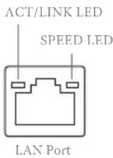
| Activity / Link LED Speed LED | |||
| Status Description Status Description | |||
| Off No Link Off | 10Mbps connection | ||
| Blinking | Data Activity | Orange | 100Mbps connection |
| On Link Green | Gbps connection | ||
** If you use a 2-channel speaker, please connect the speaker's plug into "Front Speaker Jack". See the table below for connection details in accordance with the type of speaker you use.
| Audio Output Channels | Front Speaker (No. 7) | Rear Speaker (No. 5) | Central / Bass (No. 4) | Line In (No. 6) |
| 2 V -- -- -- | ||||
| 4 V V -- -- | ||||
| 6 V V V -- | ||||
| 8 V V V V |

To enable Multi-Streaming, you need to connect a front panel audio cable to the front panel audio header. After restarting your computer, you will find the "Mixer" tool on your system. Please select "Mixer ToolBox", click "Enable playback multi-streaming", and click "ok". Choose "2CH", "4CH", "6CH", or "8CH" and then you are allowed to select "Realtek HDA Primary output" to use the Rear Speaker, Central/Bass, and Front Speaker, or select "Realtek HDA Audio 2nd output" to use the front panel audio.
*** The eSATA connector supports SATA with cables within 1 meters. The S_SATA3_3 connector is shared with the eSATA port
Chapter 1 Introduction
Thank you for purchasing ASRock X99 Extreme4 motherboard, a reliable motherboard produced under ASRock's consistently stringent quality control. It delivers excellent performance with robust design conforming to ASRock's commitment to quality and endurance.

Because the motherboard specifications and the BIOS software might be updated, the content of this documentation will be subject to change without notice. In case any modifications of this documentation occur, the updated version will be available on ASRock's website without further notice. If you require technical support related to this motherboard, please visit our website for specific information about the model you are using. You may find the latest VGA cards and CPU support list on ASRock's website as well. ASRock website http://www.asrock.com.
1.1 Package Contents
ASRock X99 Extreme4 Motherboard (ATX Form Factor)
ASRock X99 Extreme4 Quick Installation Guide
ASRock X99 Extreme4 Support CD
1 x I/O Panel Shield
1 x ASRock SLI_Bridge_2S Card
1 x ASRock 3-Way SLI-2S1S Bridge Card
4 x Serial ATA (SATA) Data Cables (Optional)
1 x HDD Saver Cable
1 x Screw for Ultra M.2 Socket
1.2 Specifications
| Platform | ATX Form Factor2oz Copper PCBHigh Density Glass Fabric PCB |
| CPU | Supports Intel® CoreTM i7 and Xeon® 18-Core ProcessorsFamily for the LGA 2011-3 SocketDigi Power design12 Power Phase designSupports Intel® Turbo Boost 2.0 TechnologySupports Untied Overclocking Technology |
| Chipset | Intel® X99 |
| Memory | Quad Channel DDR4 Memory Technology8 x DDR4 DIMM SlotsSupports DDR4 3000+(OC)*/2933+(OC)/2800(OC)/2400 (OC)/2133/1866/ 1600/1333/1066 non-ECC, un-buffered memory* Please refer to Memory Support List on ASRock's website for more information. (http://www.asrock.com/)Supports non-ECC RDIMM (Registered DIMM)Supports DDR4 ECC, un-buffered memory/RDIMM with Intel® Xeon® processors E5 series in the LGA 2011-3 Socket Max. capacity of system memory: 128GB (see CAUTION)Supports Intel® Extreme Memory Profile (XMP) 2.015μ Gold Contact in DIMM Slots |
| Expansion Slot | 3 x PCI Express 3.0 x16 Slots (PCIE1 @ x16 mode; PCIE3 @ x16 mode; PCIE5 @ x8 mode)* If you install CPU with 28 lanes, PCIE1/PCIE3/PCIE5 will run at x16/x8/x4.* If M.2 PCI Express module is installed, PCIE5 will be disabled.1 x PCI Express 2.0 x16 Slots (PCIE2 @ x4 mode)1 x PCI Express 2.0 x1 SlotSupports AMD Quad CrossFireXTM , 3-Way CrossFireXTM and CrossFireXTMSupports NVIDIA® Quad SLI TM , 3-Way SLI TM and SLI TM* If you install CPU with 28 lanes, 3-Way SLI TM is not supported.15μ Gold Contact in VGA PCIe slot (PCIE1 and PCIE3) |
Audio
7.1 CH HD Audio with Content Protection (Realtek
ALC1150 Audio Codec)
Premium Blu-ray Audio support
Supports Surge Protection (ASRock Full Spike Protection)
Supports Purity Sound™ 2
- Nichicon Fine Gold Series Audio Caps
- 115dB SNR DAC with Differential Amplifier
- TI ^® NE5532 Premium Headset Amplifier (Supports up to 600 Ohms headsets)
- Direct Drive Technology
- EMI Shielding Cover
- PCB Isolate Shielding
Supports DTS Connect
LAN
Gigabit LAN 10/100/1000 Mb/s
Giga PHY Intel ^® I218V
Supports Wake-On-LAN
Supports Lightning/ESD Protection (ASRock Full Spike Protection)
Supports Energy Efficient Ethernet 802.3az
Supports PXE
Rear Panel
1 x PS/2 Mouse Port
I/O
1 x PS/2 Keyboard Port
1 x eSATA Connector
1 x Optical SPDIF Out Port
4 x USB 2.0 Ports (Supports ESD Protection (ASRock Full Spike Protection))
4 x USB 3.0 Ports (Supports ESD Protection (ASRock Full Spike Protection))
1 x RJ-45 LAN Port with LED (ACT/LINK LED and SPEED LED)
1 x Clear CMOS Switch
HD Audio Jacks: Rear Speaker / Central / Bass / Line in /
Front Speaker / Microphone
Storage
10 x SATA3 6.0 Gb/s Connectors, support RAID (RAID 0, RAID 1, RAID 5, RAID 10 and Intel Rapid Storage 13), NCQ, AHCI, Hot Plug and ASRock HDD Saver Technology (S_SATA3_3 connector is shared with the eSATA port) (S_SATA3_2 connector is shared with Ultra M.2 Socket)
* RAID is supported on SATA3_0 \~ SATA3_5 ports only.
1 x eSATA Connector, supports NCQ, AHCI and Hot Plug
1 x Ultra M.2 Socket, supports M.2 SATA3 6.0 Gb/s module and M.2 PCI Express module up to Gen3 x4 (32 Gb/s)
Connector
1 x COM Port Header 1 x TPM Header 1 x Power LED Header 2 x CPU Fan Connectors (1 x 4-pin, 1 x 3-pin) 3 x Chassis Fan Connectors (1 x 4-pin, 2 x 3-pin) (Smart Fan Speed Control) 1 x Power Fan Connector (3-pin) 1 x 24 pin ATX Power Connector 1 x 8 pin 12V Power Connector (Hi-Density Power Connector) 1 x HDD Saver Connector 1 x PCIe Power Connector 1 x Front Panel Audio Connector 1 x Thunderbolt AIC Connector 2 x USB 2.0 Headers (support 4 USB 2.0 ports) (Supports ESD Protection (ASRock Full Spike Protection)) 1 x USB 3.0 Header (Supports 2 USB 3.0 ports) (Supports ESD Protection (ASRock Full Spike Protection))
BIOS
2 x 128Mb AMI UEFI Legal BIOS with multilingual GUI support (1 x Main BIOS and 1 x Backup BIOS) Supports Secure Backup UEFI Technology ACPI 1.1 Compliant wake up events SMBIOS 2.3.1 Support CPU, DRAM, PCH 1.05V, PCH 1.5V, VPPM Voltage Multi-adjustment
Feature
| Hardware Monitor | CPU/Chassis temperature sensing |
| CPU/Chassis/Power Fan Tachometer | |
| CPU/Chassis Quiet Fan (Auto adjust chassis fan speed by CPU temperature) | |
| CPU/Chassis Fan multi-speed control | |
| Voltage monitoring: +12V, +5V, +3.3V, CPU Input Voltage, CPU Internal Voltages | |
| OS | Microsoft® Windows® 10 64-bit / 8.1 32-bit / 8.1 64-bit / 8 32-bit / 8 64-bit / 7 32-bit / 7 64-bit |
| Certifications | FCC, CE, WHQL |
| ErP/EuP Ready (ErP/EuP ready power supply is required) |
* For detailed product information, please visit our website: http://www.asrock.com

Please realize that there is a certain risk involved with overclocking, including adjusting the setting in the BIOS, applying Untied Overclocking Technology, or using third-party overclocking tools. Overclocking may affect your system's stability, or even cause damage to the components and devices of your system. It should be done at your own risk and expense. We are not responsible for possible damage caused by overclocking.

Due to limitation, the actual memory size may be less than 4GB for the reservation for system usage under Windows* 32-bit operating systems. Windows* 64-bit operating systems do not have such limitations. You can use ASRock XFast RAM to utilize the memory that Windows* cannot use.
Chapter 2 Installation
This is an ATX form factor motherboard. Before you install the motherboard, study the configuration of your chassis to ensure that the motherboard fits into it.
Pre-installation Precautions
Take note of the following precautions before you install motherboard components or change any motherboard settings.
Make sure to unplug the power cord before installing or removing the motherboard components. Failure to do so may cause physical injuries and damages to motherboard components.
In order to avoid damage from static electricity to the motherboard's components, NEVER place your motherboard directly on a carpet. Also remember to use a grounded wrist strap or touch a safety grounded object before you handle the components.
Hold components by the edges and do not touch the ICs.
Whenever you uninstall any components, place them on a grounded anti-static pad or in the bag that comes with the components.
When placing screws to secure the motherboard to the chassis, please do not over-tighten the screws! Doing so may damage the motherboard.
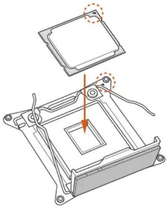
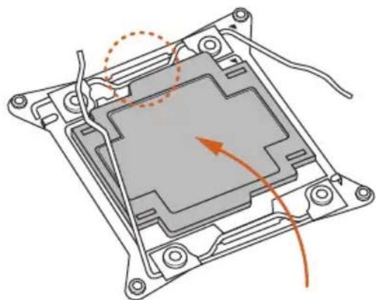
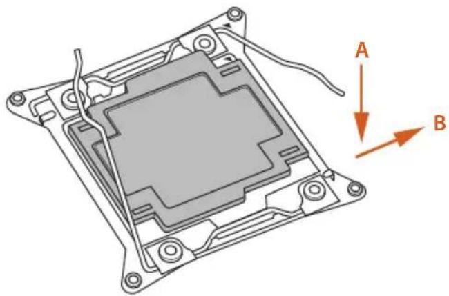
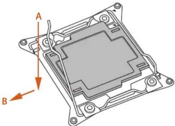
2.1 Installing the CPU

-
Before you insert the 2011-3-Pin CPU into the socket, please check if the PnP cap is on the socket, if the CPU surface is unclean, or if there are any bent pins in the socket. Do not force to insert the CPU into the socket if above situation is found. Otherwise, the CPU will be seriously damaged.
-
Unplug all power cables before installing the CPU.
CAUTION:
Please note that X99 platform is only compatible with the LGA 2011-3 socket, which is incompatible with the LGA 2011 socket (for X79 platform).
1
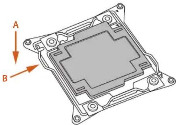
natural_image
3D technical diagram of a mechanical component with labeled arrows A and B indicating directional components (no text or symbols beyond labels)2
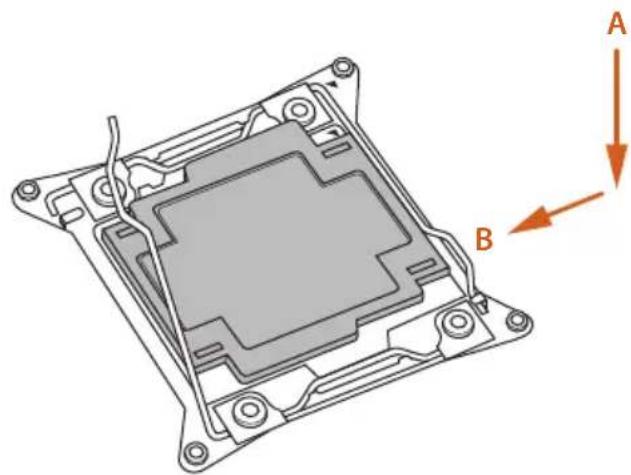
natural_image
Technical diagram of a mechanical component with labeled parts A and B, showing internal structure and mounting holes (no text or symbols beyond labels)3

natural_image
Technical line drawing of a mechanical component with labeled parts A and B, showing internal structure and mounting points (no text or symbols beyond labels)4
natural_image
Technical diagram of a computer processor with an inset showing the internal structure and mounting point (no text or symbols present)5
natural_image
Technical diagram of a mechanical component with highlighted section and orange directional arrow (no text or symbols)6
natural_image
Technical diagram of a mechanical component with labeled points A and B, showing internal structure and mounting brackets (no text or symbols beyond labels)7
natural_image
Technical diagram of a mechanical component with labeled parts A and B, showing internal structure and mounting holes (no text or symbols beyond labels)8
natural_image
Technical illustration of a mechanical component with an arrow indicating assembly or transformation (no text or symbols present)
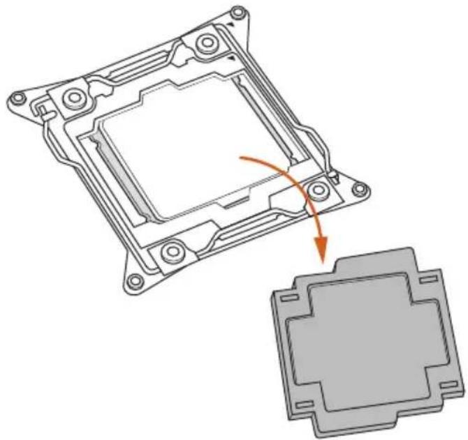
Please save and replace the cover if the processor is removed. The cover must be placed if you wish to return the motherboard for after service.
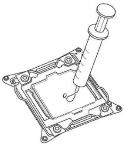
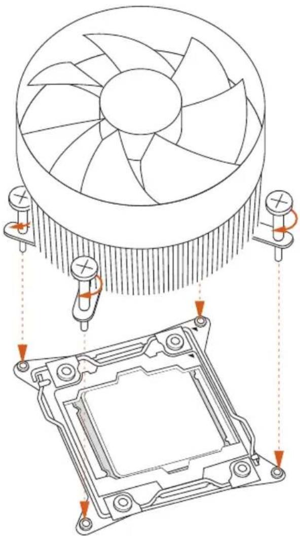
2.2 Installing the CPU Fan and Heatsink
natural_image
Technical line drawing of a mechanical assembly with a pipette inserted into a housing (no text or symbols)1
natural_image
Technical diagram showing a CPU fan and its internal components with mounting holes (no text or labels)2
text_image
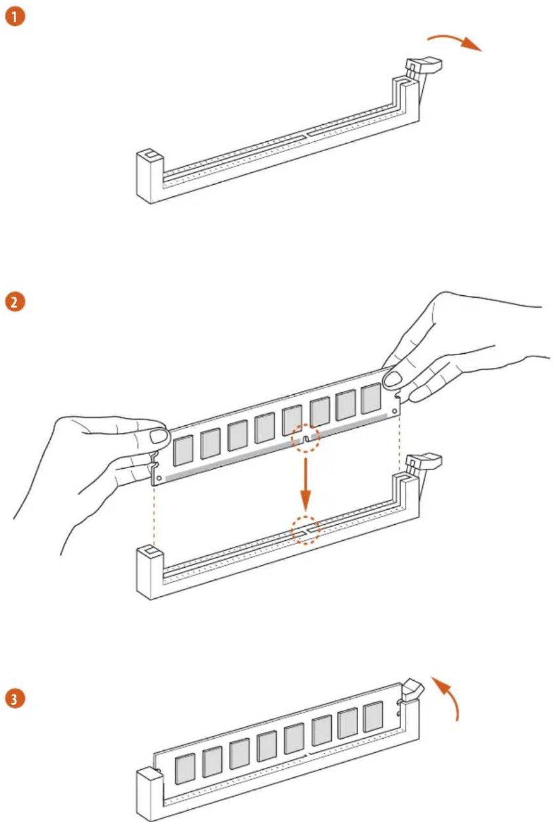
C25.3.2012.3 Installation of Memory Modules (DIMM)
This motherboard provides eight 288-pin DDR4 (Double Data Rate 4) DIMM slots, and supports Quad Channel Memory Technology.

- For quad channel configuration, you always need to install identical (the same brand, speed, size and chip-type) DDR4 DIMM pairs.
- It is not allowed to install a DDR, DDR2 or DDR3 memory module into a DDR4 slot; otherwise, this motherboard and DIMM may be damaged.
- The DIMM only fits in one correct orientation. It will cause permanent damage to the motherboard and the DIMM if you force the DIMM into the slot at incorrect orientation.
Quad Channel Memory Configuration
| Priority 1 2 | ||
| DDR4_A1 | Populated Populated | |
| DDR4_A2 | Populated | |
| DDR4_B1 | Populated Populated | |
| DDR4_B2 | Populated | |
| DDR4_C1 | Populated Populated | |
| DDR4_C2 | Populated | |
| DDR4_D1 | Populated Populated | |
| DDR4_D2 | Populated | |
Due to Intel® CPU spec definition, please install the memory modules on DDR4_A1, DDR4_B1, DDR4_C1 and DDR4_D1 for first priority. If the four DDR4 DIMM slots above are fully installed, and you want to use more than four memory modules, please install the other memory modules from left to right (from DDR4_A2, DDR4_B2, DDR4_D2 to DDR4_C2.)
If only two memory modules are installed in the DDR4 DIMM slots, then Dual Channel Memory Technology is activated. If three memory modules are installed, then Triple Channel Memory Technology is activated. If more than four memory modules are installed in the DDR4 DIMM slots, then Quad Channel Memory Technology is activated.
2.4 Expansion Slots (PCI Express Slots)
There are 5 PCI Express slots on the motherboard.

Before installing an expansion card, please make sure that the power supply is switched off or the power cord is unplugged. Please read the documentation of the expansion card and make necessary hardware settings for the card before you start the installation.
PCIe slots:
PCIE1 (PCIe 3.0 x16 slot) is used for PCI Express x16 lane width graphics cards.
PCIE2 (PCIe 2.0 x16 slot) is used for PCI Express x4 lane width cards.
PCIE3 (PCIe 3.0 x16 slot) is used for PCI Express x16 lane width graphics cards.
PCIE4 (PCIe 2.0 x1 slot) is used for PCI Express x1 lane width cards.
PCIE5 (PCIe 3.0 x16 slot) is used for PCI Express x8 lane width graphics cards.
* If M.2 PCI Express module is installed, PCIE5 will be disabled.
PCIe Slot Configurations (For CPU with 40 PCIe lanes)
Single Graphics Card x16 N/AN/AN/AN/A
Two Graphics Cards in
CrossFireX ^TM or SLI ^TM x16 N/A x16 N/A N/A Mode
Three Graphics Cards in
3-Way CrossFireX ^TM Mode x16 N/A x16 N/A x8 or 3-Way SLI ^TM Mode
PCIe Slot Configurations (For CPU with 28 PCIe lanes)
Single Graphics Card x16 N/A N/A N/A N/A
Two Graphics Cards in
CrossFireX ^TM or SLI ^TM x16 N/A x8 N/A N/A Mode
Three Graphics Cards in
3-Way CrossFireX ^TM Mode X16 N/A X8 N/A X4
*3-Way SLI ^TM Mode is not supported for CPU with 28 PCIe lanes.

For a better thermal environment, please connect a chassis fan to the motherboard's chassis fan connector (CHA_FAN1, CHA_FAN2 or CHA_FAN3) when using multiple graphics cards.
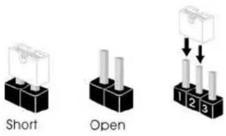
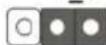
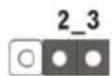
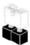
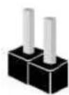
2.5 Jumpers Setup
The illustration shows how jumpers are setup. When the jumper cap is placed on the pins, the jumper is "Short". If no jumper cap is placed on the pins, the jumper is "Open". The illustration shows a 3-pin jumper whose pin1 and pin2 are "Short" when a jumper cap is placed on these 2 pins.
text_image
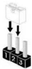
Short Open 1 2 3Clear CMOS Jumper (CLRCMOS1)
(see p.1, No. 25)
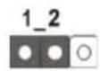
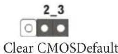
CLRCMOS1 allows you to clear the data in CMOS. To clear and reset the system parameters to default setup, please turn off the computer and unplug the power cord from the power supply. After waiting for 15 seconds, use a jumper cap to short pin2 and pin3 on CLRCMOS1 for 5 seconds. However, please do not clear the CMOS right after you update the BIOS. If you need to clear the CMOS when you just finish updating the BIOS, you must boot up the system first, and then shut it down before you do the clear-CMOS action. Please be noted that the password, date, time, and user default profile will be cleared only if the CMOS battery is removed.

The Clear CMOS Switch has the same function as the Clear CMOS jumper.
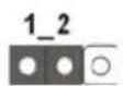
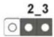
BIOS Selection Jumper
(BIOS_SEL1)
(see p.1, No. 24)
1 2
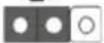
Default
(Main BIOS)
2 3
Backup BIOS
This motherboard has two BIOS onboard, a main BIOS (BIOS_A) and a backup BIOS (BIOS_B), which enhances protection for the safety and stability of your system. Normally, the system works on the main BIOS. However, if the main BIOS is corrupted or damaged, please use a jumper cap to short pin2 and pin3, then the backup BIOS will take over on the next system boot. After that, use “Secure Backup UEFI” in BIOS setup utility to copy the BIOS file to the main BIOS to ensure normal system operation. For the sake of system safety, users cannot update the backup BIOS manually. Users may refer to the BIOS LED (BIOS_A_LED or BIOS_B_LED) to identify which BIOS is activated currently.
2.6 Onboard Headers and Connectors

Onboard headers and connectors are NOT jumpers. Do NOT place jumper caps over these headers and connectors. Placing jumper caps over the headers and connectors will cause permanent damage to the motherboard.
System Panel Header (9-pin PANEL1) (see p.1, No. 20)
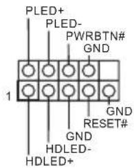
text_image
PLED+ PLED- PWRBTN# GND 1 GND RESET# GND HDLED- HDLED+Connect the power switch, reset switch and system status indicator on the chassis to this header according to the pin assignments below. Note the positive and negative pins before connecting the cables.

PWRBTN (Power Switch):
Connect to the power switch on the chassis front panel. You may configure the way to turn off your system using the power switch.
RESET (Reset Switch):
Connect to the reset switch on the chassis front panel. Press the reset switch to restart the computer if the computer freezes and fails to perform a normal restart.
PLED (System Power LED):
Connect to the power status indicator on the chassis front panel. The LED is on when the system is operating. The LED keeps blinking when the system is in S1/S3 sleep state. The LED is off when the system is in S4 sleep state or powered off (S5).
HDLED (Hard Drive Activity LED):
Connect to the hard drive activity LED on the chassis front panel. The LED is on when the hard drive is reading or writing data.
The front panel design may differ by chassis. A front panel module mainly consists of power switch, reset switch, power LED, hard drive activity LED, speaker and etc. When connecting your chassis front panel module to this header, make sure the wire assignments and the pin assignments are matched correctly.
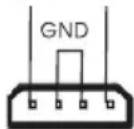
Power LED Header
(3-pin PLED1)
(see p.1, No. 18)
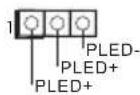
Please connect the chassis power LED to this header to indicate the system's power status.
Serial ATA3 Connectors
(S_SATA3_0_1:
see p.1, No. 11)
(S_SATA3_2_3:
see p.1, No. 12)
(SATA3_0_3:
see p.1, No. 13)
(SATA3_1_4:
see p.1, No. 14)
(SATA3_2_5:
see p.1, No. 15)
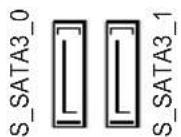
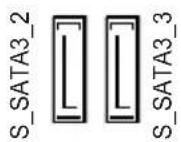
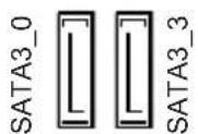
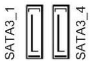
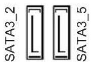
These ten SATA3 connectors support SATA data cables for internal storage devices with up to 6.0 Gb/s data transfer rate. If the eSATA port on the rear I/O has been connected, the internal S_SATA3_3 will not function. If the Ultra M.2 Socket has been occupied, the internal S_SATA3_2 will not function.
* RAID is supported on SATA3_0 \~ SATA3_5 ports only.
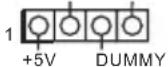
USB 2.0 Headers
(9-pin USB4_5)
(see p.1, No. 22)
(9-pin USB6_7)
(see p.1, No. 23)
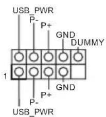
text_image
USB_PWR P- P+ GND DUMMY 1 GND P- P+ USB_PWRBesides four USB 2.0 ports on the I/O panel, there are two headers on this motherboard. Each USB 2.0 header can support two ports.
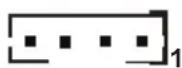
USB 3.0 Header
(19-pin USB3_4_5)
(see p.1, No. 9)
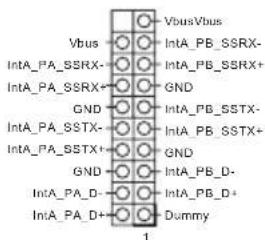
text_image
Vbus/Vbus IntA_PB_SSRX- IntA_PB_SSRX+ GND IntA_PB_SSTX- IntA_PB_SSTX+ GND IntA_PB_D- IntA_PB_D+ Dummy 1Besides four USB 3.0 ports on the I/O panel, there is one header on this motherboard. This USB 3.0 header can support two ports.
Front Panel Audio Header
(9-pin HD_AUDIO1)
(see p.1, No. 28)
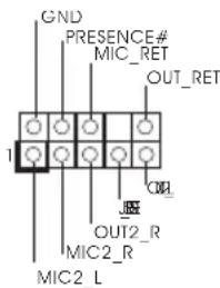
text_image
GND PRESENCE# MIC_RET OUT_RET 1 OUT2_R MIC2_R MIC2_LThis header is for connecting audio devices to the front audio panel.

- High Definition Audio supports Jack Sensing, but the panel wire on the chassis must support HDA to function correctly. Please follow the instructions in our manual and chassis manual to install your system.
- If you use an AC'97 audio panel, please install it to the front panel audio header by the steps below:
A. Connect Mic_IN (MIC) to MIC2_L.
B. Connect Audio_R (RIN) to OUT2_R and Audio_L (LIN) to OUT2_L.
C. Connect Ground (GND) to Ground (GND).
D. MIC_RET and OUT_RET are for the HD audio panel only. You don't need to connect them for the AC'97 audio panel.
E. To activate the front mic, go to the "FrontMic" Tab in the Realtek Control panel and adjust "Recording Volume".
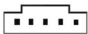
Chassis Speaker Header
(4-pin SPEAKER1)
(see p.1, No. 19)
DUMMY SPEAKER
Please connect the chassis speaker to this header.
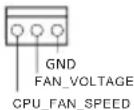
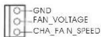
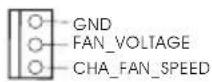
Chassis and Power Fan
Connectors
(4-pin CHA_FAN1)
(see p.1, No. 17)
(3-pin CHA_FAN2)
(see p.1, No. 16)
(3-pin CHA_FAN3)
(see p.1, No. 10)
(3-pin PWR_FAN1)
(see p.1, No. 31)
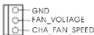
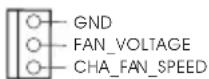

Please connect fan cables to the fan connectors and match the black wire to the ground pin. CHA_FAN fan speed can be controlled through UEFI or A-Tuning.
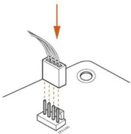
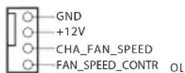
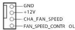
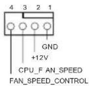
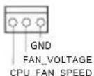
CPU Fan Connectors
(4-pin CPU_FAN1)
(see p.1, No. 4)
(3-pin CPU_FAN2)
(see p.1, No. 6)
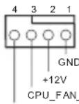
FAN_SPEED_CONTROL
This motherboard provides a 4-Pin CPU fan
(Quiet Fan) connector.
If you plan to connect a
3-Pin CPU fan, please
connect it to Pin 1-3.
ATX Power Connector
(24-pin ATXPWR1)
(see p.1, No. 8)
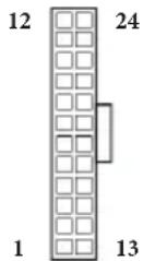
This motherboard provides a 24-pin ATX power
connector. To use a 20-pin
ATX power supply, please
plug it along Pin 1 and Pin
13.
ATX 12V Power
Connector
(8-pin ATX12V1)
(see p.1, No. 3)
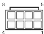
This motherboard provides an 8-pin ATX 12V
power connector. To use a
4-pin ATX power supply,
please plug it along Pin 1
and Pin 5.
PCIe Power Connector
(4-pin PCIE _PWR1)
(see p.1, No. 30)

Please connect a 4 pin molex
power cable to this connector
when more than three graphics
cards are installed.
HDD Saver Connector
(4-pin SATA_PWR_1)
(see p.1, No. 21)
Please connect the HDD Saver
Cable to this connector to
manage the power state of HDD.
Thunderbolt AIC
Connector
(5-pin TBT1)
(see p.1, No. 29)
Please connect a Thunderbolt™
add-in card (AIC) to this
connector via the GPIO cable.
Serial Port Header
(9-pin COM1)
(see p.1, No. 26)
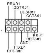
This COM1 header supports a serial port module.
TPM Header
(17-pin TPMS1)
(see p.1, No. 27)
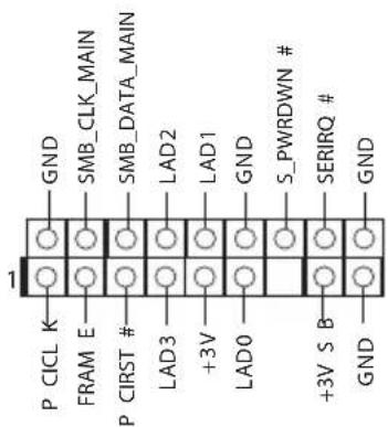
text_image
GND SMB_CLK_MAIN SMB_DATA_MAIN LAD2 LAD1 GND S_PWRDOWN # SERIRQ # GND P CICL K FRAM E P CIRST # LAD3 +3V LAD0 +3V S B GNDThis connector supports Trusted Platform Module (TPM) system, which can securely store keys, digital certificates, passwords, and data. A TPM system also helps enhance network security, protects digital identities, and ensures platform integrity.
2.7 Smart Switches
The motherboard has a Clear CMOS Switch, allowing users to clear the CMOS values.
Clear CMOS Switch
(CLRCBTN)
(see p.3, No. 14)
Clear CMOS Switch
allows users to quickly
clear the CMOS values.

This function is workable only when you power off your computer and unplug the power supply.
2.8 M.2\_SSD (NGFF) Module Installation Guide
The M.2, also known as the Next Generation Form Factor (NGFF), is a small size and versatile card edge connector that aims to replace mPCIe and mSATA. The Ultra M.2 Socket (M2_1) can accommodate either a M.2 SATA3 6.0 Gb/s module or a M.2 PCI Express module up to Gen3 x4 (32 Gb/s). Please be noted that the Ultra M.2 Socket (M2_1) is shared with the S_SATA3_2 connector; you can only choose either the Ultra M.2 Socket (M2_1) or the S_SATA3_2 connector to use.
* If M.2 PCI Express module is installed, PCIE5 will be disabled.
Installing the M.2\_SSD (NGFF) Module
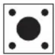
natural_image
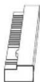
Pure technical line drawing of a rectangular component with internal cutouts and a small knob (no text or symbols)Step 1
Prepare a M.2_SSD (NGFF) module and the screw.
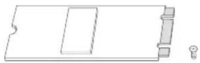
text_image
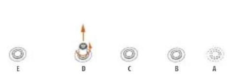
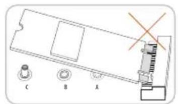
E D C B A 1 2 3 4 5Step 2
Depending on the PCB type and length of your M.2_SSD (NGFF) module, find the corresponding nut location to be used.
No. 1 2 3 4 5
| Nut Location A B C D E | |||||
| PCB Length | 3cm | 4.2cm | 6cm | 8cm | 11cm |
| Module Type | Type2230 | Type 2242 | Type2260 | Type 2280 | Type 22110 |
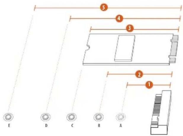
text_image
E D C B A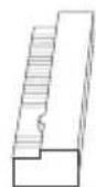
Step 3
Move the standoff based on the module type and length. The standoff is placed at the nut location D by default. Skip Step 3 and 4 and go straight to Step 5 if you are going to use the default nut. Otherwise, release the standoff by hand.
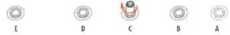
Step 4
Peel off the yellow protective film on the nut to be used. Hand tighten the standoff into the desired nut location on the motherboard.
text_image
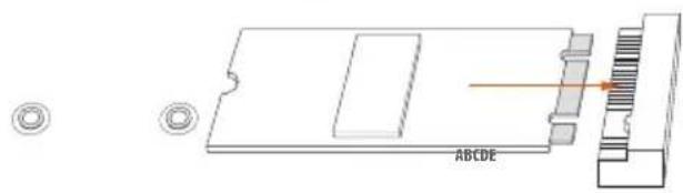
Technical diagram showing a mechanical assembly with labeled components A, B, and C, including a cross symbol indicating a specific part.Step 5
Align and gently insert the M.2 (NGFF) SSD module into the M.2 slot. Please be aware that the M.2 (NGFF) SSD module only fits in one orientation.
natural_image
Technical diagram of a mechanical component with labeled parts and an arrow indicating direction (no readable text or symbols)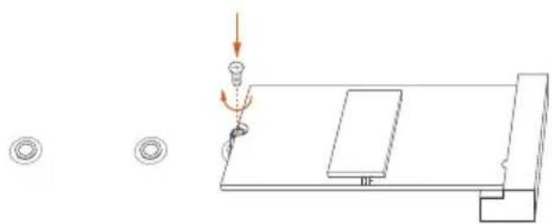
natural_image
Pure technical diagram showing a mechanical assembly with no text, numbers, or symbolsStep 6
Tighten the screw with a screwdriver to secure the module into place. Please do not overtighten the screw as this might damage the module.
M.2\_SSD (NGFF) Module Support List
PCIe Interface SATA Interface
Plector PX-G512M6e ADATA AXNS381E-128GM-B
Plector PX-G256M6e ADATA AXNS381E-256GM-B
SanDisk SD6PP4M-128G Crucial CT120M500SSD4/120G
SanDisk SD6PP4M-256G Crucial CT240M500SSD4/240G
Samsung XP941-512G (MZHPU512HCGL) Intel SSDSCKGW080A401/80G
Kingston RBU-SM2280S3/120G
For the latest updates of M.2_SSD (NFGG) module support list, please visit our website for details: http://www.asrock.com
2.9 HDD Saver Cable Installation Guide
The HDD Saver Connector on this motherboard allows you to switch on and off the connected HDDs via software when needed. This design secures more privacy, saves more energy, and extends the HDDs' lifespans. Please follow the steps below to install the HDD Saver Cable.
Connection Diagram
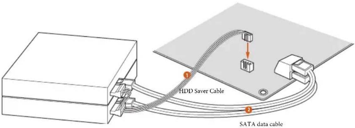
text_image
HDD Saver Cable SATA data cable*The diagram shown here is for reference only.
- Connect one end of the HDD Saver Cable to the HDD Saver Connector (SATA_PWR_1) placed near the SATA ports. Then connect the SATA power connector(s) to your SATA HDD(s).
* The HDD Saver Connector supports up to two SATA HDDs.
- Connect one end of the SATA data cable to a SATA port on the motherboard. Then connect the other end to your SATA HDD(s).

For the software configuration, please refer to the section 3.2 "A-Tuning" in the user manual.
1 Einleitung
(OC)/2400(OC)/2133/1866/1600/1333/1066 non-ECC, un-buffered
bit / 8 64-bit / 7 32-bit / 7 64-bit
Certifica- zioni
bit / 8 64-bit / 7 32-bit / 7 64-bit
Certifica- ciones
(OC)/2800(OC)/2400(OC)/2133/1866/1600/1333/1066 Non-ECC Unbuffered
32-bit / 8 64-bit / 7 32-bit / 7 64-bit
Сертификация
bit / 8 64-bit / 7 32-bit / 7 64-bit
Certificações
Apagar o Jumper CMOS (CLRCMOS1)
(ver p.1, N.° 9)

Padrão
Apagar CMOS
/ 8 64 bit / 7 32 bit / 7 64 bit
Belgeler
lidir)
(3-pin CHA_FAN2) (bkz sf.1, No. 16)
(3-pin CHA_FAN3) (bkz sf.1, No. 10)
(3-pin PWR_FAN1) (bkz sf.1, No. 31)
(3-pin CPU_FAN2) (bkz sf.1, No. 6)
natural_image
Simple graphic with a magnifying glass icon and a horizontal line, no text or symbols present.1.1 パッケージの内容
1.2 仕様
| CPU | TM |
text_image
128GB μTM
TM
TM
TM
μ
LAN
I/O
os
32-bit / 8 64-bit / 7 32-bit / 7 64-bit


1.3 ジャンパー設定
Short
Open
(CLRCMOS1)
1 2

2 3


(BIOS_SEL1)
BIOS
Giga PHY Intel" I218V
支持远程唤醒
bit / 8 64-bit / 7 32-bit / 7 64-bit
认证
、CE、WHQL
If you need to contact ASRock or want to know more about ASRock, you're welcome to visit ASRock's website at http://www.asrock.com; or you may contact your dealer for further information. For technical questions, please submit a support request form at http://www.asrock.com/support/tsd.asp
ASRock Incorporation
2F., No.37, Sec. 2, Jhongyang S. Rd., Beitou District,
Taipei City 112, Taiwan (R.O.C.)
ASRock EUROPE B.V.
Bijsterhuizen 11-11
6546 AR Nijmegen
The Netherlands
Phone: +31-24-345-44-33
Fax: +31-24-345-44-38
ASRock America, Inc.
13848 Magnolia Ave, Chino, CA91710
U.S.A.
Phone: +1-909-590-8308
Fax: +1-909-590-1026