Pro Melt 2 - Electric oven RCBS - Free user manual and instructions
Find the device manual for free Pro Melt 2 RCBS in PDF.

| Product Type | Electric lead casting furnace |
| Brand | RCBS |
| Model | Pro Melt 2 |
| Crucible capacity | 11.3 kg (25 lb) of alloy |
| Maximum temperature | Approximately 425°C (800°F) |
| Temperature control | Digital thermostat with dual display (PV/SV) |
| Power supply | 120 V AC, 50/60 Hz, estimated power 800 W |
| Spout type | Bottom feed spout with shut-off pin |
| Casting methods | Pressure and gravity casting |
| Crucible material | Heat-resistant steel |
| Approximate dimensions | 32 x 28 x 40 cm |
| Approximate weight | 10 kg |
| Handle | Articulated handle to operate the spout |
| Mold rest | Height adjustable with guide collars |
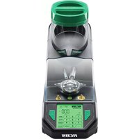
| Lid | Hinged, allows heating molds |
| Ventilation | Built-in fan for cooling |
| LED indicators | Out, AT, AL (overheat alarm) |
| Electrical safety | 3-wire power cord, recommended 30 mA residual-current circuit breaker |
| Warranty | 2-year limited (parts and labor) |
| Maintenance | Clean surfaces with special lead detergent, do not immerse |
Frequently Asked Questions - Pro Melt 2 RCBS
User questions about Pro Melt 2 RCBS
0 question about this device. Answer the ones you know or ask your own.
Ask a new question about this device
Download the instructions for your Electric oven in PDF format for free! Find your manual Pro Melt 2 - RCBS and take your electronic device back in hand. On this page are published all the documents necessary for the use of your device. Pro Melt 2 by RCBS.
USER MANUAL Pro Melt 2 RCBS
PRO MELT-2 Electric Lead Furnace
PRODUCT INSTRUCTIONS
Part # 81199
LANGUAGE PAGES
English 4-13
Français 14-23
Espanol 24-33
Deutsch 34-43
Italiano 44-53
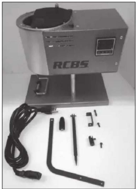
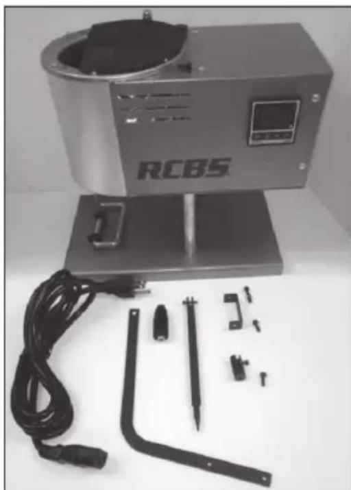
Box Contents
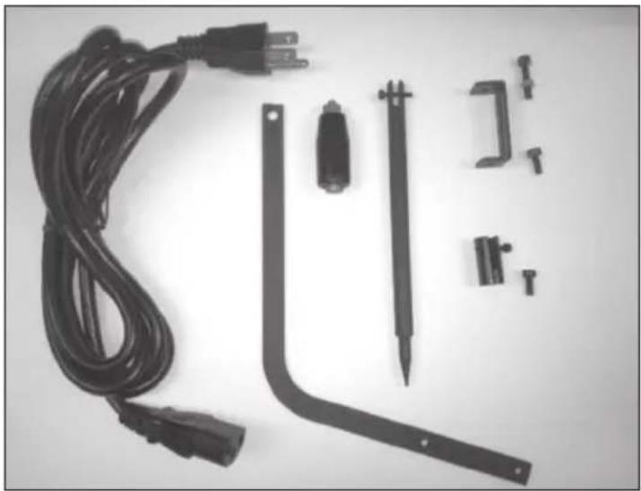
Bagged Components
(AC power cord is stored in melting pot)
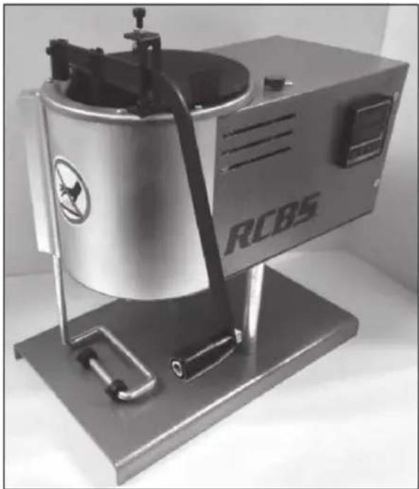
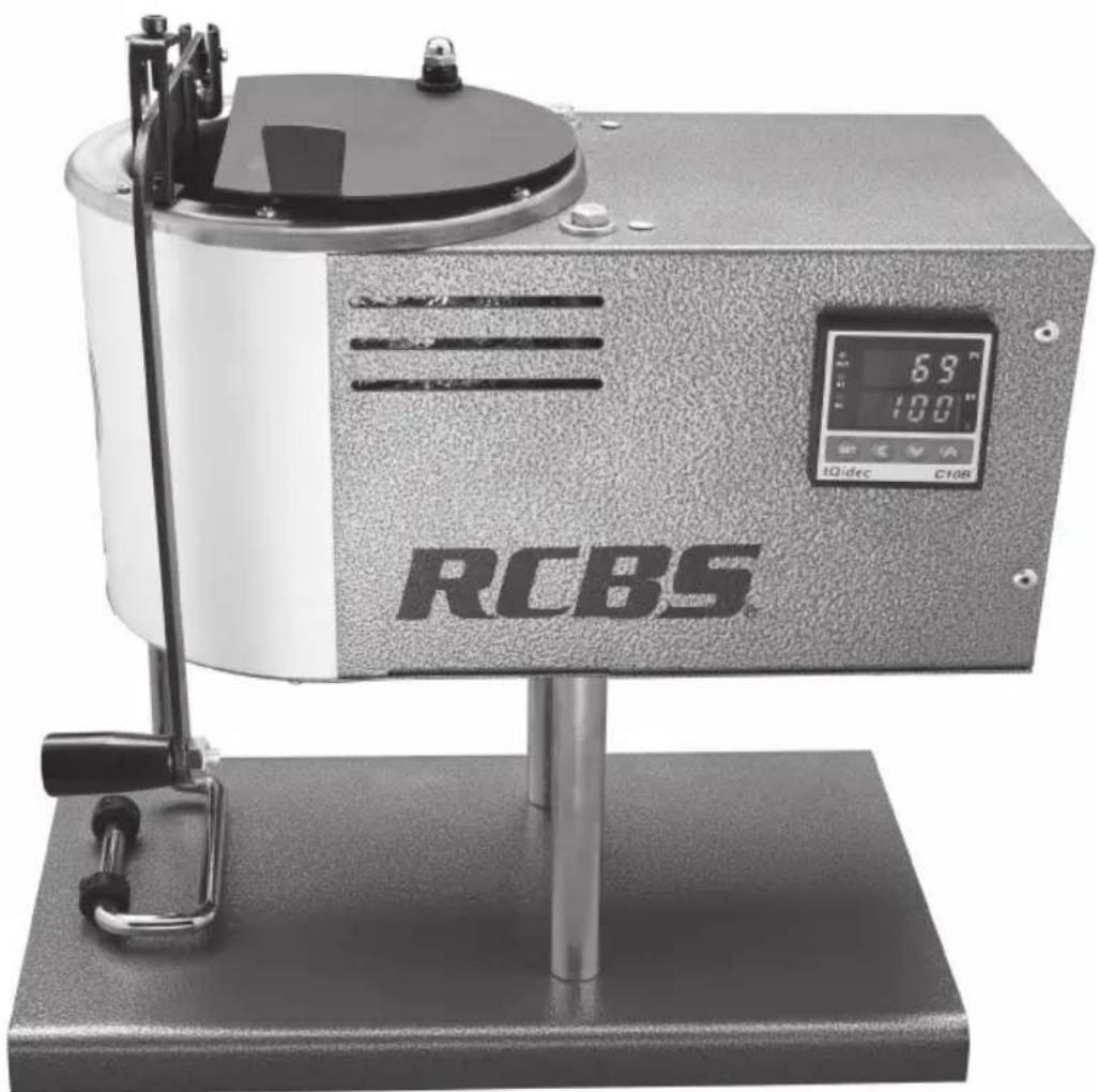
Assembled Unit

WARNING!
BEFORE USING THE RCBS PRO MELT-2, READ THESE INSTRUCTIONS CAREFULLY TO FULLY LEARN HOW TO SAFELY OPERATE THE RELATED EQUIPMENT.
FAILURE TO PROPERLY OPERATE THE RELATED EQUIPMENT CAN RESULT IN SEVERE PERSONAL INJURY AND/OR EQUIPMENT DAMAGE.
If you have any questions while assembling or operating this tool, Call us at 1-800-379-1732 (U.S. or Canada)
Monday - Friday 5:00 a.m. - 5:00 p.m. Pacific Time (hours may vary)
Or email us at rcbs.tech@vistaoutdoor.com
This instruction manual contains specific safety and operating information. It should be considered a permanent part of your equipment and remain with the equipment at all times for easy reference.

WARNING: Melting lead and casting lead objects will expose you and others in the area to lead, which is known to cause birth defects, other reproductive harm and cancer.
REDUCING EXPOSURE: Lead contamination in the air, in dust, and on your skin is invisible. Keep children and pregnant women away during use and until cleanup is complete. Risk can be reduced-but not eliminated-with strong ventilation; washing hands immediately after use of these products before eating or smoking; and careful cleaning of surfaces and floors with disposable wipes, after lead dust has had a chance to settle. Use a lead-specific cleaner with EDTA, or a high-phosphate detergent (like most detergents sold for electric dishwashers), and bag wipes for disposal.
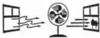
USE STRONG VENTILATION
SAFETY
Reloading is an enjoyable and rewarding hobby that can be conducted safely. But carelessness or negligence can make reloading hazardous. This product has been designed from the beginning with the user's safety in mind.
When reloading, some safety rules must be followed. By observing these rules, the chance of a hazardous occurrence causing personal injury or property damage is minimized.
GENERAL
- Use all reloading equipment as the manufacturer recommends. Study the instructions carefully and become thoroughly familiar with the operation of the product. Don't take short cuts.
- Observe "good housekeeping" in the reloading area. Keep tools and components neat, clean and orderly. Promptly and completely clean up primer and powder spills.
- Reload only when you can give your undivided attention. Do not reload when fatigued or ill.
Develop a reloading routine to avoid mistakes. Avoid haste — load at a leisurely pace.
- Always wear adequate eye protection.
ELECTRICALWARNINGS
WARNING: CARE SHOULD BE USED WHEN OPERATING ELECTRICAL APPLIANCES IN WET AREAS OR AROUND WATER. OPERATING UNIT ON A GFCI OUTLET WITH A RATED TRIP CURRENT OF 30mA IS RECOMMENDED TO PROVIDE PROTECTION AGAINST ELECTRIC SHOCK. THE INSTALLATION OF A GFCI CIRCUIT SHOULD ONLY BE CARRIED OUT BY A QUALIFIED ELECTRICIAN.
CAUTION: Leave the unit unplugged until you have read all the instructions and are ready to use.
- This product is equipped with a three wire, detachable power cord; plug only into a proper outlet.
- Do not work on wet floors.
- Do not plug into electrical outlet until the proper voltage is supplied.
- Locate all electric cords away from moisture, rain and moving parts.
- Periodically check all cords for worn/frayed spots and replace or repair to code if needed.
- Never submerge unit in water or any other liquid in an attempt to clean the unit.
- Never use unit if power cord becomes damaged.
- Never attempt to disassemble unit.
- Always use on a flat level surface.
- Always disconnect power cord before adjusting, cleaning, setup, etc.
- Always unplug unit when not in use.
- Allow for adequate room around unit to allow for cooling. Do not store items next to unit while in use. Keep cooling fans and vents clear of any obstructions (rags, bags, boxes, etc.).
DANGER OF ELECTRIC SHOCK! To prevent life-threatening electric shock, please observe the following:
- Do not use while bathing.
- Never immerse the device or power cord in water or other liquid.
- Never touch the power plug with wet hands, especially when inserting or removing the plug.
- If the unit has fallen in water during operation, do not touch the unit. Remove the power plug from the socket first.
- Do not spray water or liquid over the device.
- When removing the cord from the socket, grab the power plug, not the cord.
- Protect the power cord from damage.
- If there is damage to the power plug, cord, housing, or other parts of the device, do not use.
Disassembly of this device should only be performed by qualified professionals at RCBS.
CASTING
Overexposure to lead can be harmful. Lead contributes to health impairment and diseases which occur after periods of lead exposure over long periods of time.
- Bullet casting should not be conducted in a confined space or in an enclosed room. Ensure that well-ventilated areas are used to avoid build-up and breathing of lead dust, fumes and fluxing fumes. Good ventilation includes continuous cross-ventilation by large amounts of fresh air.
- Particulate masks should be worn during bullet casting activities.
- When casting or otherwise working with molten lead, always wear effective eye protection, appropriate protective clothing, leather or thick cotton work gloves, and shoes that cover
your feet and ankles completely. Protective clothing could include coveralls or one-piece jumpsuits. However, the clothing should not be used for any other activities. It should be laundered separately from other clothing. These precautions will minimize the likelihood of any lead dust being scattered around in other living areas.
- Maintain good housekeeping practices to ensure that surfaces are as free as practical of the accumulation of lead dust. Vacuuming is the preferred method. Compressed air should not be used.
- Hands, face and hair should be washed after working around lead dust, fumes or fluxing fumes, and prior to eating, drinking, smoking or applying cosmetics. The likelihood of lead ingestion increases if you don't.
- At all times, keep small children well away from the casting area.
- Do not smoke, eat or handle food when handling lead.
- Always make certain bullet mould, lead dipper and bullet metal are totally free of moisture.
- All electrical melting pots should be grounded to reduce risk of electrical shock.
- Melting pots in use should never be left unattended.
- Be sure your melting pot and heat source are stable, and the table or bench is solid.
- An ingot mould or other suitable container should be placed under the nozzle to catch lead that may leak.
- Never allow moisture near molten lead. If moisture is introduced to the molten lead, the liquid will vaporize instantly generating a steam eruption causing lead to be sprayed erratically, potentially causing injury to user.
- Never run furnace without lead in the pot.
- Do not attempt to move furnace when it is hot.
RECORD KEEPING
- Keep complete records of reloads. Apply a descriptive label to each box showing the date produced, and the primer, powder and bullet used.
Since RCBS has no control over the choice of components, the manner in which they are assembled, the use of this product, or the guns in which the resulting ammunition may be used, no responsibility, either expressed or implied, is assumed for the use of ammunition reloaded with this product.
INTRODUCTION
The heart of your RCBS PRO MELT-2 is the accurate, industrial quality thermostat located inside the unit. The placement of the remote sensor, on the bottom surface of the melting pot, senses the actual temperature of the molten alloy. The bottom-feed nozzle ensures smooth, even pouring with the weight of alloy in the melting pot providing the pressure needed to fill mould cavities and eliminate shrinkage voids. A hinged cover warms mould blocks and keeps debris from entering melting pot.
UNPACKING
Unpack the PRO MELT-2 carefully and look for the items and their associated hardware listed below. Refer to the parts list for identification.
PRO MELT-2 Body and Base
- AC Power Cord
- Nozzle Shut Off Pin, M3x0.5x16mm
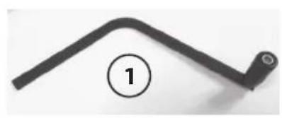
- Handle
- Handle Knob, M6x1x5mm, M6 Hex Nut
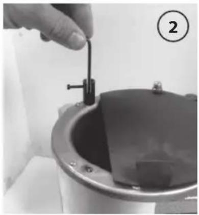
- Handle Fulcrum, M3x0.5x19mm, M4x0.7x14mm
- Adjustment Bracket, M4x0.7x24mm, M4 Hex Nut, M4x0.7x14mm
- Mould Guide Collars (2), M4x0.7x8mm (2)
Should any parts be missing, please notify your dealer immediately.
INSTALLATION
The PRO MELT-2 has been shipped assembled; however, there are a few items that will require additional assembly as described below. A reference table listing the fasteners and tools used for each item is provided as well.
ASSEMBLY
- Using a 5mm hex key wrench and 10mm wrench, attach Handle Knob to Handle (Photo 1, next page).
- Assemble Handle Fulcrum to Melting Pot, using 2.5mm hex key wrench (Photo 2).
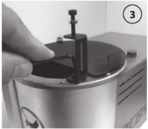
- Assemble Adjustment Bracket to Melting Pot, using 2.5mm hex key wrench (Photo 3).
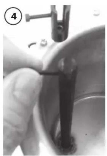
- Place the Nozzle Shut Off Pin into the Melting Pot. Ensure both the cap screws, on the Handle Fulcrum and the Nozzle Shut Off Pin, are backed off enough to allow for clearance of the Handle (Photo 4).
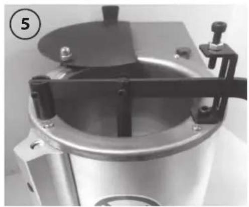
- Insert the Handle through the slots in the Adjustment Bracket, Nozzle Shut Off Pin and Handle Fulcrum. Make necessary adjustments to ensure the Handle is resting freely in the handle slot on all three components. Once adjustments are made remove Handle and tighten the cap screws on the Handle Fulcrum and Adjustment Bracket to secure in place. Re-insert the Handle and secure in place by tightening the cap screws on the Handle Fulcrum and Nozzle Shut Off Pin, ensuring the cap screws are aligned with the holes in the Handle (Photo 5).
| FASTENER & TOOL REFERENCE | ||
| Part Fasteners Tools | ||
| Handle Knob M6x1x46mm, M6 Hex Nut 5mm hex key, 10mm wrench | ||
| Handle Fulcrum M3x0.5x16mm, M4x0.7x10mm 2mm | hex key, 2.5mm hex key | |
| Adjustment Bracket | M4x0.7 x 20mm, M4 Hex Nut, M4x0.7x10mm | 2.5mm hex key, 7mm wrench |
| Mould Guide Collars (2) | M4x0.7x8mm (2) 1.5mm hex key | |
| Nozzle Shut Off Pin | M3x0.5x16mm 2mm hex key | |
Bullet Mould Rest Adjustment
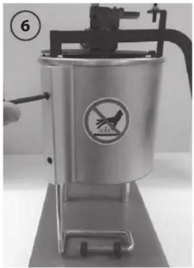
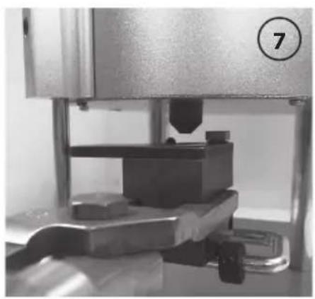
- Using a 3.5mm hex key wrench loosen the two set screws securing the mould rest. Adjust the rest by sliding it up to obtain the desired height from nozzle to mould block (Photos 6 & 7).
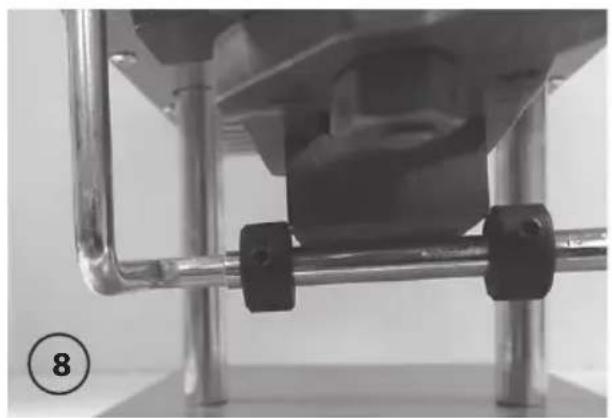
- Adjust the location of the two mould guide collars, using a 1.5mm hex key wrench loosen one of the collars and slide along the mould rest to set either the right or left limit for the mould block when placed on rest. Once limit is set secure in place and adjust the second guide collar, ensure there is enough clearance to effectively place and remove mould block during use (Photo 8).
TO USE:
- Plug the AC power cord into the PRO MELT-2 unit, then plug the other end of the AC power cord into the correct AC receptacle.
- Add ingots, or small pieces of lead to the melting pot, stacking them against the sides as much as possible.
- Using the Digital Thermostat, set the desired Melting Pot temperature. (See "Digital Thermostat Operation" on pg.11, and "Suggested Casting Temperatures" below for specific alloys).
| Suggested Casting Temperatures | |
| Alloy Casting Temp. p. (°F) | |
| Pure Lead 700 | |
| 1:20 Tin - Lead 700 | |
| 1:10 Tin - Lead 700 | |
| Linotype 775 | |
| Wheel Weights* 775 | |
| *Composition & properties vary | |
- Continue to add ingots, or small pieces of lead to achieve desired Melting Pot capacity. Melting Pot capacity is 25 lbs. of material. Do not operate PRO MELT-2 with less than 1^ of alloy in Melting Pot.
Pour Methods/Flow Adjustment
Pressure Pour: Align hole in sprue plate with nozzle and raise to contact, lift operating handle to dispense molten lead. Release handle to stop the pour and lower the mould block. Move to next cavity, if using a multi-cavity mould block.
Gravity Pour: Position the mould under the spout and lift the handle to allow the stream of molten material to flow through the sprue plate, filling the mould cavity.
Flow Adjustment: If the dispensing speed is too quick or too slow, adjust the Stop Screw and Jamb Nut adjustment at the top of the Adjustment Bracket (pg. 9, Photo 3) to the desired pour speed.
WARNING! Do not attempt to dip the mould block directly into the molten material in the pot. Any moisture or oils on the mould block will cause a violent reaction creating the potential for personal injury or death.
Warming Mould Blocks
- After all material has been added to Melting Pot, rotate cover, to completely cover the melting pot, this will speed up heating process and aids in keeping debris out of melting pot.
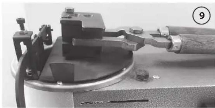
- The cover can also be used for heating Mould Blocks. Simply place Mould Block on top of cover to warm while waiting for material in Melting Pot to reach desired casting temperature (Photo 9).
USAGE NOTES
- For bullet casting instructions, consult the instruction book you received with your bullet moulds.
- When melting metals to produce an alloy, always be certain that you are using the recommended metals and recommended amounts.

CAUTION: Do not use if exposed to environments outside the temperature range of 32-122°F (0-50°C)
Dual Display
- PV: Present Value (Measured Pot Temperature)
- SV : Set Value (Desired Pot Temperature)
LED Indicators
- Out: Heating element is on and heating Melting Pot
AT : Thermostat is adjusting output to ensure the measured Melting Pot temperature (PV) matches that of the desired Melting Pot temperature (SV) - AL : Illuminates to alert user when PV temperature is 30-50 °F higher than SV (0 - 10°C)
OPERATION
To set desired temperature:
- Depress SET button. SV Display will begin to flash.
- Use the "A" (increase value) and "V" (decrease value) buttons to set your desired Melting Pot temperature.
- When desired value is reached use the < button to move to next value and use "A" and/or "V" buttons to increase or decrease the value.
- When the desired temperature is displayed (SV), depress the SET button to confirm desired temperature and begin heating.
To turn off the unit:
- Depress SET button, display will begin to flash.
- Use " ^ , "V", and < < " buttons to set SV temperature to 0^ , this will turn off Pot heating.
- The fan will continue to run to cool unit.
- When unit cools down and PV display reads 160 °F (71 °C), unplug AC cord from unit to completely power down unit.
CAUTION:Burn hazard.
Do not touch the unit during or after operation until cooled.
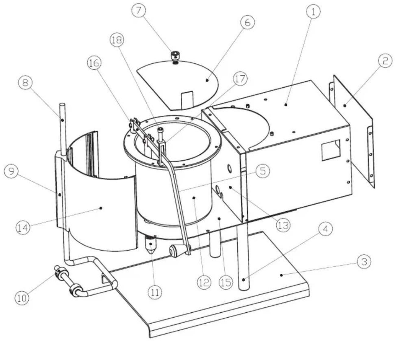
PARTS REFERENCE
| Part # | Name Qty | |
| 1 Body | 1 | |
| 2 Back Board | 1 | |
| 3 Base | 1 | |
| 4 Support Rod | 2 | |
| 5 Handle | 1 | |
| 6 Lid | 1 | |
| 7 Lid | Pivot | 1 |
| 8 Mould Rest | 1 | |
| 9 Holder | 1 |
| Part # | Name Qty | |
| 10 Mould Guide Collar 2 | ||
| 11 Nozzle 1 | ||
| 12 Melting Pot 1 | ||
| 13 Insulating Plate 1 | ||
| 14 Front Panel 1 | ||
| 15 Bottom Plate 1 | ||
| 16 Handle Fulcrum 1 | ||
| 17 Adjustment Bracket 1 | ||
| 18 Flow Adjustment Screw 1 | ||
TWO YEAR LIMITED WARRANTY
Congratulations on the purchase of your new RCBS PRO MELT-2. Your new PRO MELT-2 is warranted to be free from defects in material or workmanship for a period of two (2) years from the date of purchase. This warranty is extended only to the original consumer purchaser. Should you believe that your PRO MELT-2 is defective in material or workmanship, you must return it to RCBS, postage paid, for evaluation. If defective, the product will be repaired or replaced at RCBS's option, at no charge
Send a check in the amount of ten dollars ((10) U.S. payable to RCBS Operation for return shipping and handling, along with the unit to:
RCBS
605 Oro Dam Blvd East
Oroville, California 95965
Warranty services cannot be provided without meeting the above requirements.
THIS WARRANTY DOES NOT COVER DEFECTS OR DAMAGE RESULTING FROM: CARELESSNESS, MISUSE, IMPROPER INSTALLATION, MODIFICATION, OR IF YOUR PRO MELT-2 HAS BEEN ALTERED OR REPAIRED BY ANYONE OTHER THAN FACTORY PERSONNEL.
WARRANTY SERVICES CANNOT BE PROVIDED WITHOUT MEETING THE ABOVE REQUIREMENTS.
Please retain this warranty certificate for future reference.
THE IMPLIED WARRANTYES OF MERCHANTABILITY AND FITNESS FOR A PARTICULAR PURPOSE ARE LIMITED TO THE DURATION OF THIS LIMITED WARRANTY. RCBS OPERATION IS NOT LIABLE FOR DAMAGES IN EXCESS OF THE PURCHASE PRICE OF THE PRODUCT AND UNDER NO CIRCUMSTANCES SHALL RCBS OPERATION BE LIABLE FOR CONSEQUENTIAL OR INCIDENTIAL DAMAGES. HOWEVER, SOME STATES DO NOT ALLOW LIMITATIONS ON INCIDENTIAL OR CONSEQUENTIAL DAMAGES, SO THE ABOVE LIMITATION OR EXCLUSION MAY NOT APPLY TO YOU.
The above warranty provides the sole and exclusive warranty available to the customer in the event of a defect in material or workmanship in the PRO MELT-2. This warranty gives you specific legal rights, and you may also have other rights which vary from state to state.
CONTACT US:
RCBS
605 Oro Dam Blvd East
Oroville, California 95965
1-800-379-1732 (US or Canada)
Fax Number: 530-533-1647
E-mail: rcbs.tech@vistaoutdoor.com
Website: www.rcbs.com
Contenu de la boîte
CONSERVATION DES INFORMATIONS
605 Oro Dam Blvd East
605 Oro Dam Blvd East
Site Web: www.rcbs.com
605 Oro Dam Blvd East
Oroville, California, 95965
605 Oro Dam Blvd East
Oroville, California, 95965
605 Oro Dam Blvd East
Oroville, California 95965
605 Oro Dam Blvd East
Oroville, California, 95965
Website: www.rcbs.com
605 Oro Dam Blvd East
Oroville, California 95965
605 Oro Dam Blvd East
Oroville, California, 95965
1-800-379-1732 (USA o Canada)
We think we make the world's best reloading equipment.
If you agree, please tell your friends.
If you disagree, tell us—we want to do something about it!
Customer Service
1-800-379-1732 (U.S. or Canada)
Hours: Monday - Friday, 5:00 a.m. - 5:00 p.m. Pacific Time (hours may vary)
E-mail rcbs.tech@vistaoutdoor.com, or visit www.rcbs.com
RCBS · 605 Oro Dam Blvd. East · Oroville, CA 95965