2kWh LFP Battery - Battery charger ECOFLOW - Free user manual and instructions
Find the device manual for free 2kWh LFP Battery ECOFLOW in PDF.

| Product Type | Lithium iron phosphate (LFP) battery for modular power system |
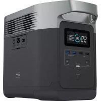
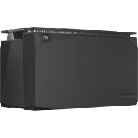
| Brand and Model | EcoFlow 2kWh LFP Battery |
| Nominal Capacity | 2048 Wh (40 Ah) |
| Nominal Voltage | 51.2 V |
| Battery Chemistry | LiFePO₄ (Lithium Iron Phosphate) |
| Cell Configuration | 16S2P (32 cells of 20 Ah) |
| Dimensions (L × W × H) | 348 × 198 × 285 mm (13.7 × 7.8 × 11.2 in) |
| Net Weight | 17.1 kg (37.7 lb) |
| Max Continuous Charge Current | 32 A |
| Max Continuous Discharge Current | 80 A |
| Charge Cut-off Voltage | 57.6 V |
| Discharge Cut-off Voltage | 40 V |
| Nominal Lifespan | 3,000 cycles at 80% remaining capacity |
| Protection Rating (IP) | IP54 (dust and splash water resistant) |
| Charge Temperature Range | -20 °C to 50 °C (with automatic heating below 0°C) |
| Discharge Temperature Range | -20 °C to 50 °C |
| Maximum Operating Humidity | 90% RH |
| Battery Management System (BMS) | Built-in protections: overcharge, overdischarge, overcurrent, short circuit, high/low temperature, cell balancing |
| Heating Functions | Automatic charge heating (requires ≥250 W); manually activatable discharge heating via app |
| Connectivity | RJ45 port for communication (CAN Bus) compatible with EcoFlow console or wireless dongle (optional) |
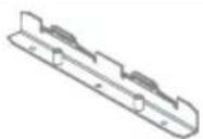
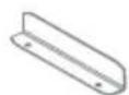
| Box Contents | 2 kWh LFP battery, user manual and warranty card, wall mount bracket, screws |
| Warranty | Refer to the provided warranty card |
Frequently Asked Questions - 2kWh LFP Battery ECOFLOW
User questions about 2kWh LFP Battery ECOFLOW
0 question about this device. Answer the ones you know or ask your own.
Ask a new question about this device
Download the instructions for your Battery charger in PDF format for free! Find your manual 2kWh LFP Battery - ECOFLOW and take your electronic device back in hand. On this page are published all the documents necessary for the use of your device. 2kWh LFP Battery by ECOFLOW.
USER MANUAL 2kWh LFP Battery ECOFLOW
LFP Battery User Manual
text_image
ECOFLOW SCWH LFP BATTERY ECOFLOW SCWH LFP BATTERYDisclaimer
Please read this User Manual and ensure you understand it fully before using the product. Please keep this User Manual properly for future reference. Any incorrect usage of this product may cause severe injury to the user or others, damage to the product, or loss of property. By using this product, the user will be deemed as having understood, recognized, and accepted all the terms and contents of this User Manual, and will be responsible for any incorrect usage and all consequences arising therefrom. EcoFlow hereby disclaims any liability for any losses due to the user's failure to use the product according to the User Manual.
In compliance with laws and regulations, EcoFlow shall have the final right to interpret this document and all related documents for this product. Any update, revision, or termination of the contents thereof, if necessary, shall be made without prior notice, and users may visit EcoFlow official website for the latest information of the product.
1. Safety Instructions
1.1 Prohibitions
- It is strictly prohibited to place this battery near heat sources, such as fire or heating furnace.
- It is strictly prohibited to allow this battery to contact with any liquid. Do not immerse this battery in water. Do not use this battery in rainy, damp, or wet environment.
- It is prohibited to use this battery in strong static or strong magnetic field environment.
- It is prohibited to disassemble this battery in any way or puncture this battery with sharp objects.
- It is prohibited to connect the positive and negative terminals of the battery directly with wires or any metal objects.
- It is prohibited to dismantle or replace the battery cells.
- It is prohibited to stack heavy objects other than another EcoFlow LFP battery on top of this battery.
- It is prohibited to place this battery in an unventilated or dusty environment.
1.2 General Notices
- Beware when using unofficial components or accessories. Please visit authorized EcoFlow channels for official components and accessories information.
- If the battery is compromised or battery cells are exposed, do not attempt to repair it yourself. Please have it inspected and repaired by authorized EcoFlow repair centers.
- In case of accidental leakage of chemicals inside this battery, do not touch or inhale. In case of accidental contact with skin or eyes, wash with plenty of clean water and seek medical treatment immediately.
- Do not operate this battery while wearing metal objects such as watch, necklace, and bracelet to avoid causing accidental short circuits. If this battery catches fire, immediately use fire extinguisher or fire fighting equipment water or mist, sand, fire blanket, dry powder fire extinguisher, carbon dioxide fire extinguisher.
- When using this battery for the first time, if the battery appears broken or has abnormal smell, do not continue to use this battery and return it to sellers.
- If this battery accidentally falls into water during use, place it in a safe, open area and stay away from this battery until it is completely dry, and this battery should not be reused and should be disposed properly in accordance with the disposal methods in Section 8.2 of this User Manual.
- If the battery charging exceeds regular charging time, charging should be stopped. Overcharge may cause the battery to overheat, to smoke and deform, or to combust.
- This battery should be kept out of the reach of children and pets.
1.3 Handling Precautions
- When handling this battery, use the non-slip metal handles from this battery for proper handling.
- When handling this battery, be sure to secure it properly and keep it in a flat position.
- Please handle with care.
2. EcoFlow App
Control, monitor, and customize your EcoFlow Modular Power System wirelessly with the EcoFlow App. Download at: https://download.ecoflow.com/app
Privacy Policy
By using EcoFlow Products, Applications and Services, you consent to the EcoFlow Term of Use and Privacy Policy, which you can access via the "About" section of the "User" page on the EcoFlow App or on the official EcoFlow website at https://www.ecoflow.com/policy/terms-of-use and https://www.ecoflow.com/policy/privacy-policy

text_image
QR code with embedded logo and text, likely for digital scanning and linking to online contentEcoFlow app
3. What's in the Box
text_image
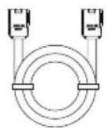
SCOPL SU HIV. US 100%LFP Battery User Manual an Battery Cable
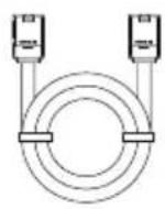
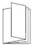
Warranty Card
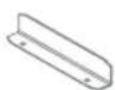
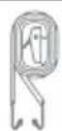
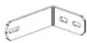
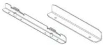
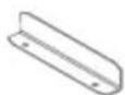
Wall Mounting Clamp
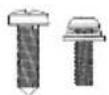
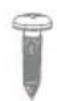
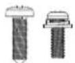
Screws
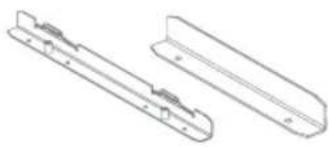
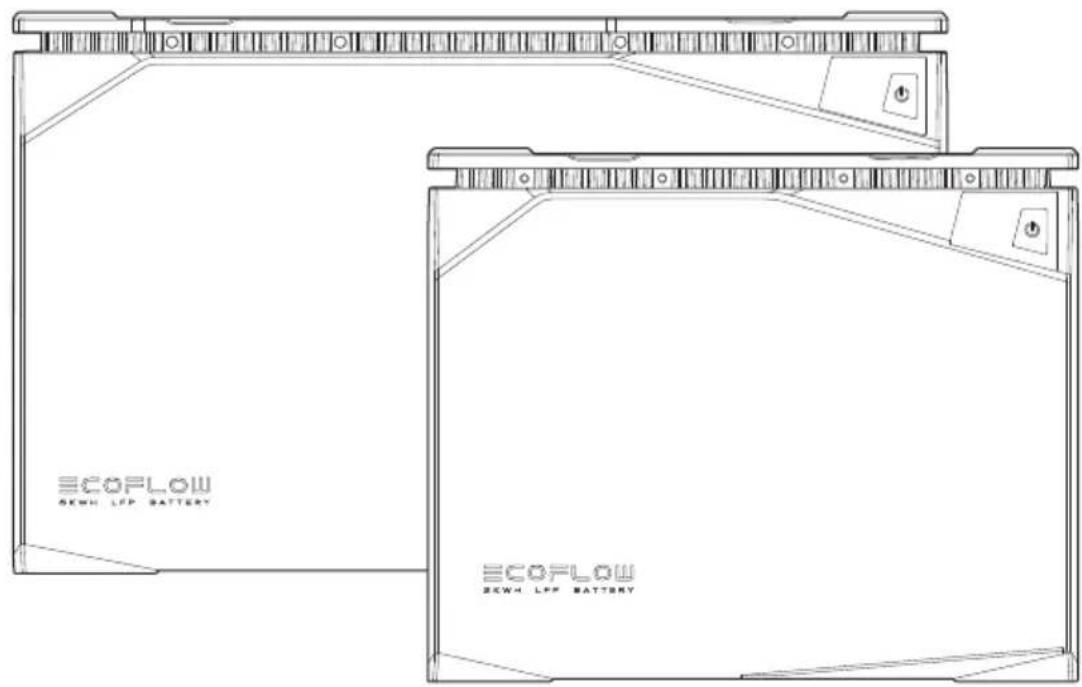
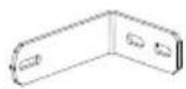
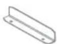
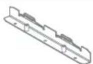
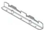
natural_image
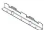
Technical line drawing of two mechanical components with mounting holes (no text or symbols)Mounting Strap

4. Battery Specifications
4.1 General Information
| 5kWh LFP Battery 2kWh LFP Battery | ||
| Net weight | Approx. 89.5 lbs(40.6 kg) | Approx. 37.7 lbs(17.1 kg) |
| Dimensions | 19.7 x 10.2 x 11.8 in500 x 260 x 300 mm | 13.7 x 7.8 x 11.2 in348 x 198 x 285 mm |
| Nominal Capacity | 5120Wh(100Ah) | 2048Wh(40Ah) |
| Nominal Voltage | 51.2V | 51.2V |
| Configuration | 16S1P | 16S2P |
| Charging Cut-off Voltage | 57.6V | 57.6V |
| Discharging Cut-off Voltage | 40V | 40V |
| Max Continued Charging Current | 80A | 32A |
| Max Continued Discharge current | 100A | 80A |
| Battery Chemistry | LiFePO_4 | LiFePO_4 |
| Cycle life | 3,500 cycles to 80% capacity | 3,000 cycles to 80% capacity |
| IP Rating | IP54 | IP54 |
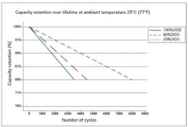
4.2 Cycle Curve
line
| Number of cycles | 100%DD | 80%DD | 50%DD | | ---------------- | ------ | ----- | ----- | | 0 | 100% | 100% | 100% | | 1000 | ~95% | ~98% | ~97% | | 2000 | ~90% | ~93% | ~92% | | 3000 | ~85% | ~88% | ~87% | | 4000 | ~80% | ~83% | ~82% | | 5000 | ~75% | ~78% | ~77% | | 6000 | ~70% | ~73% | ~72% | | 7000 | ~65% | ~68% | ~67% | | 8000 | ~60% | ~63% | ~62% | | 9000 | ~55% | ~58% | ~57% |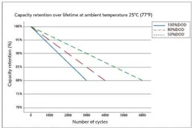
line
| Number of cycles | 100%DOD | 80%DOD | 50%DOD | | ---------------- | -------- | ------- | ------- | | 0 | 100% | 100% | 100% | | 1000 | 95% | 93% | 94% | | 2500 | 88% | 86% | 89% | | 3000 | 80% | 82% | 85% | | 4000 | - | 80% | 82% | | 5000 | - | - | 80% | | 6000 | - | - | 79% |5kWh LFP Battery 2kWh LFP Battery
*To obtain longer battery life, it is recommended to use partial charging and discharging, i.e. with a depth of discharge (DOD) of less than 80%. The DOD is the ratio of the amount of battery discharge to the rated capacity of the battery.
4.3 Operating Temperature
| 5kWh LFP Battery 2kWh LFP Battery | ||
| Discharge Temperature Range | -20°C~50°C (-4°F~122°F) | -20°C~50°C (-4°F~122°F) |
| Charge Temperature Range | -20°C~50°C (-4°F~122°F)(auto-heating below 0°C (32°F)) | -20°C~50°C (-4°F~122°F)(auto-heating below 0°C (32°F)) |
| Humidity Range | Max. 90%RH | Max. 90%RH |
| Storage Temperature | -20°C~50°C (-4°F~122°F)(optimal 15°C~25°C (59°F~77°F)) | -20°C~50°C (-4°F~122°F)(optimal 15°C~25°C (59°F~77°F)) |
*Whether this battery can be charged or discharged depends on actual temperature of the battery.
*This battery will activate auto-heating function when charging temperature falls below 0°C (32°F).
5. Battery Overview
5.1 Introduction to Battery
There are two types of EcoFlow LFP Battery, 5kWh LFP Battery and 2kWh LFP Battery, both of which use the safest and most reliable type of lithium iron phosphate battery cell (LiFePO _4 or LFP). The nominal voltage of a single LFP cell is 3.2V. The 5kWh LFP battery consists of 16 cells (100AH each cell) in 16S1P and the 2kWh LFP battery consists of 32 cells (20AH each cell) in 16S2P. Nominal voltage of both batteries is 16x3.2V=51.2V.
Both batteries have built-in battery management system, which keeps the battery system operating in a reasonable condition at all time and extends the battery service life.
The battery has a built-in auto-heating system to ensure that the battery can be charged safely and quickly at -20^ 50^ (-4^ 122^) .
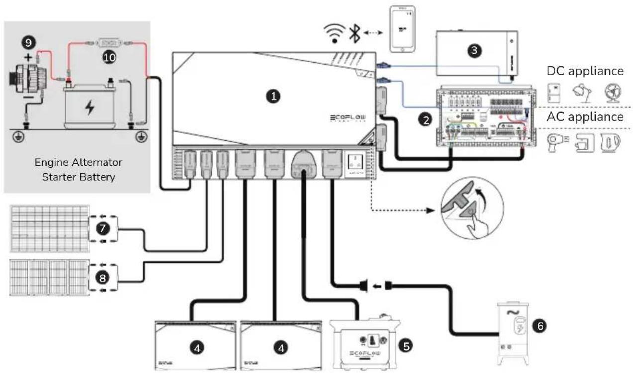
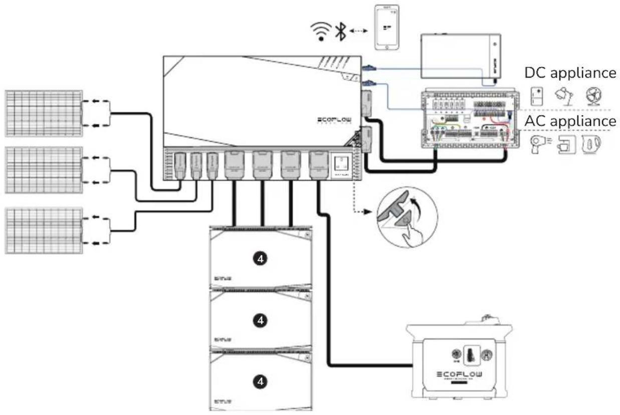
5.2 EcoFlow Power Kits
The EcoFlow Power Kits consist of the EcoFlow Power Hub, LFP Battery, AC/DC Smart Distribution Panel, Power Kit Console, Rigid/Flexible/Foldable Solar Panel, and Smart Generator.
The Modular Power System aims to meet the needs of customers in off-grid scenarios such as caravans, off-grid build, recreational marine, and home backup.
The Modular Power System is extremely easy to install straight out of the box. Using 48V battery system significantly reduces the gauge and weight of battery cables, reducing wiring cost and increasing safety. The system's power consumption can be monitored anytime and anywhere via EcoFlow App.
The Modular Power System supports multiple charging methods, including solar charging, alternator charging, smart generator charging, and AC charging. It is capable of outputting 12V or 24V DC and 120V AC (according to local standards) via the AC/DC Smart Distribution Panel, allowing it to power most AC and DC devices.
Caravan & Recreational Marine
Off-grid Build & Home Backup
flowchart
graph TD
    A["ECOFLow"] --> B["DC appliance"]
    A --> C["AC appliance"]
    B --> D["Mobile Device"]
    C --> E["Smart Speaker"]
    D --> F["Network Interface"]
    E --> G["Device Interface"]
    F --> H["Network Interface"]
    G --> I["ECOFLow System"]
    H --> I
    style A fill:#f9f,stroke:#333
    style B fill:#ccf,stroke:#333
    style C fill:#ccf,stroke:#333
    style D fill:#dfd,stroke:#333
    style E fill:#dfd,stroke:#333
    style F fill:#dfd,stroke:#333
    style G fill:#dfd,stroke:#333
    style H fill:#dfd,stroke:#333
- EcoFlow Power Hub
- AC/DC Smart Distribution Panel
- Power Kit Console
- EcoFlow 2kWh/5kWh LFP Battery
-
EcoFlow Smart Generator
-
Shore Power/Grid Power
- Rigid/Flexible Solar Panel
- Foldable / Portable Solar Panel
- Vehicle Alternator
- Fuse-100A (Not included)
Note: The figure shows the different types of sockets in different countries. It is for reference only, please refer to the actual product.
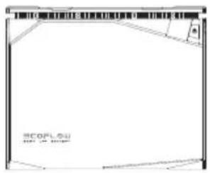
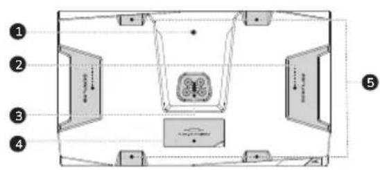
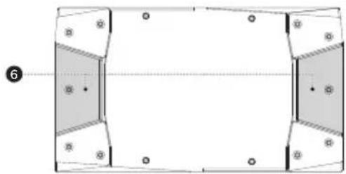
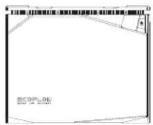
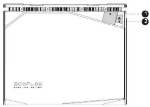
5.3 Battery Appearance
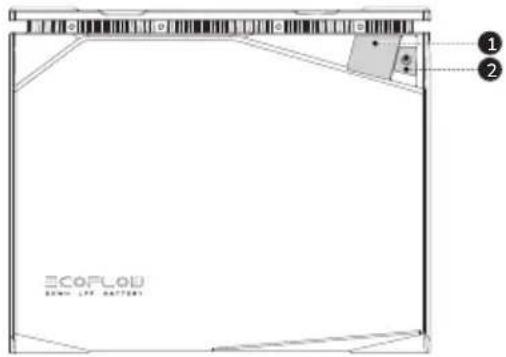
text_image
Diagram of a room layout with numbered compartments and directional arrows indicating movement or flow- LFP Battery Polarity Adapter Screw Position
- Handle
- LFP Battery Male Port
natural_image
Pure geometric diagram with shaded regions and dots, no text or symbols present- Fuse Cover
- Recess for Strap
- Base Stacking Recess
text_image
ECOFL0D BOMA LTR. BATTERY- Digital Display
- Power On/Off Button
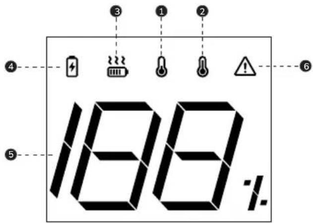
text_image
188%- Low Temperature Indicator
- High Temperature Indicator
- Heating Status Indicator
- Charging Status Indicator
-
Battery Level Indicator
-
Protection Warning Indicator
Protection types include:
Over-discharge protection
Overcharge protection
Overload protection
Short-circuit protection
Overcurrent protection, etc.
6. Battery Operation
6.1 Battery On and Off
The battery can be switched on in two ways, via charging or via buttons.
The buttons that can be used to switch on the battery include,
- the battery main power button;
- the EcoFlow Power Kit Console main power button;
- the EcoFlow Power Hub main power button.
The battery can be switched off via,
- the battery main power button;
- the EcoFlow Power Kit Console main power button;
- the EcoFlow Power Hub main power button;
- EcoFlow App.
text_image
Diagram showing network connection between a device and an ECOFLOW device, with labeled components and connections.Switching On: Press and hold the power button for 2 seconds. The battery will switch on. Short press the power button to wake up the screen. After switching on, the display will be illuminated and show the remaining battery level.
Switching Off: Press and hold the power button for 3 seconds. The battery will switch off.
Display Sleep: After switching on the battery via the power button, the display will remain lit for 5 mins and will then automatically switch off. To switch the display on or off, short press the power button.
6.2 Charging and Discharging the Battery
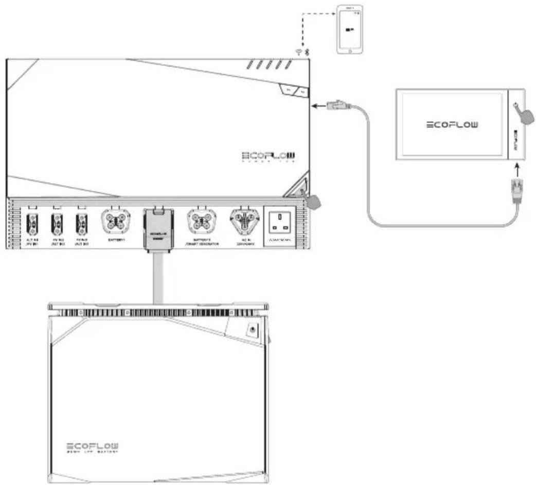
6.2.1 Connecting the Battery to the EcoFlow Power Kits
Connect the battery to Power Kits for charging (as follows):
text_image
Technical diagram showing connection between an ECOFLow device and a network interface with multiple connected modules labeled in Chinese.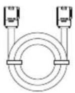
* The LFP Battery Cable consists of an AWG4 power cable (max. continuous current 100A) and a communication cable.
6.2.2 Connecting the Battery to Third-Party Power Systems
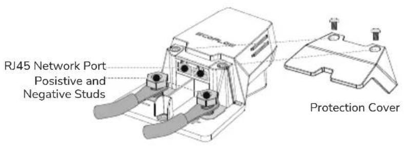
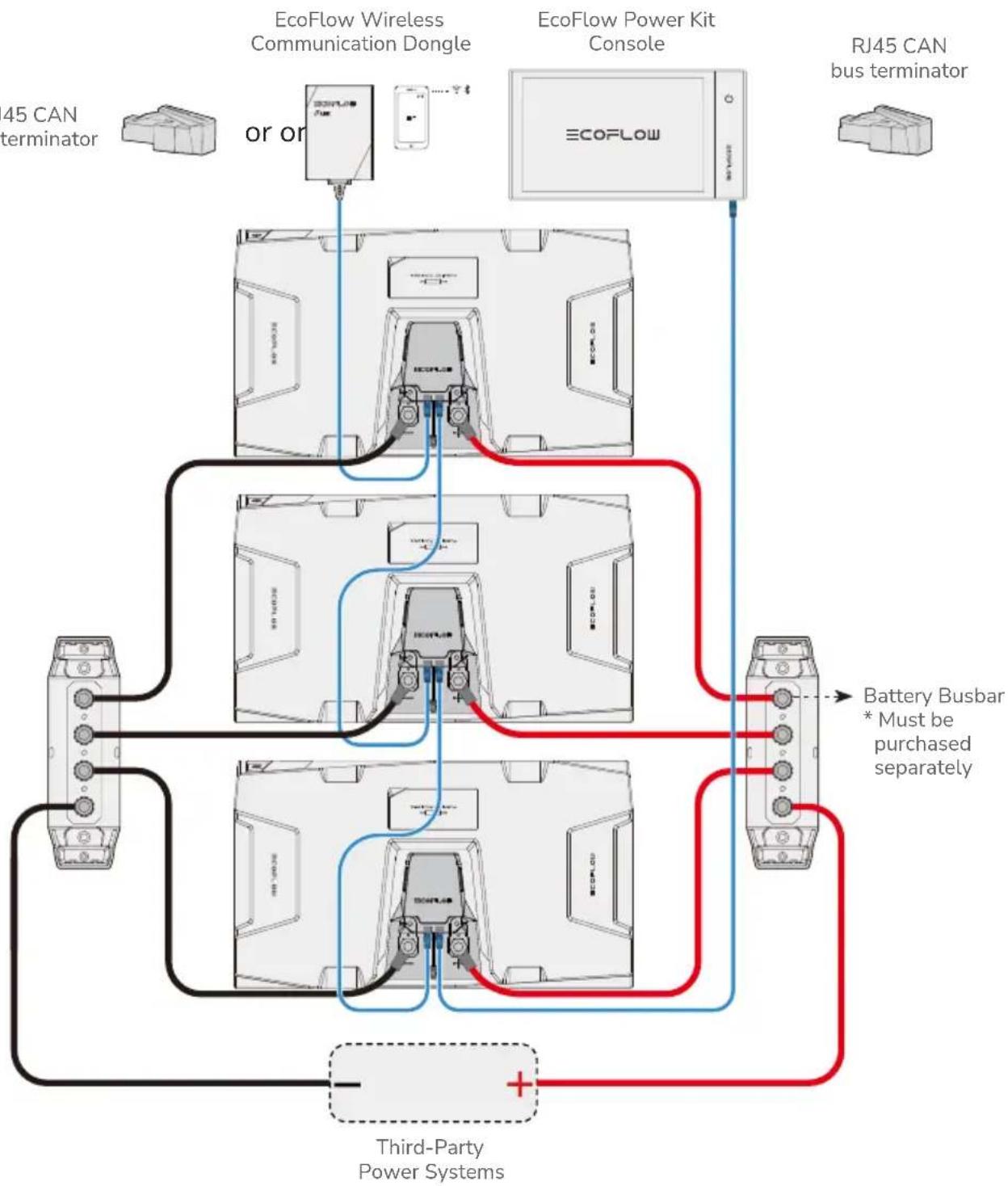
EcoFlow LFP Battery is compatible with most commercially available 40V\~60V third-party power systems. The user can monitor the operating status of each battery by connecting the EcoFlow Power Kit Console or EcoFlow Wireless Communication Dongle via the RJ45 port.
text_image
RJ45 Network Port Positive and Negative Studs Protection Cover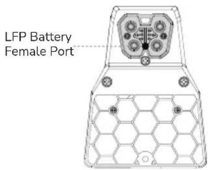
text_image
LFP Battery Female Port* Must be purchased separately
* EcoFlow Power Kit Console or EcoFlow Wireless Communication Dongle must be purchased separately.
This adapter comes with two RJ45 CAN Bus ports, each port can be connected to EcoFlow Wireless Communication Dongle, Power Kit Console or another adapter. When two or more battery packs are connected and the RJ45 CAN Bus port is not connected to either of the above modules, an RJ45 CAN bus terminator MUST be connected to the port to ensure proper communication throughout the system.
flowchart
graph TD
    A["45 CAN terminator"] --> B["or or"]
    B --> C["EcoFlow Wireless Communication Dongle"]
    C --> D["EcoFlow Power Kit Console"]
    D --> E["RJ45 CAN bus terminator"]
    F["Battery Busbar * Must be purchased separately"] --> D
    G["Third-Party Power Systems"] --> H["+"]
    I["ECOFLOW"] --> J["ECOFLOW"]
    style A fill:#f9f,stroke:#333
    style B fill:#ccf,stroke:#333
    style C fill:#cfc,stroke:#333
    style D fill:#fcc,stroke:#333
    style E fill:#cff,stroke:#333
    style F fill:#ffc,stroke:#333
    style G fill:#cfc,stroke:#333
    style H fill:#fcc,stroke:#333
The user should select appropriate connection cable according to the power of the third-party power system and the discharge current of the battery.
The following table shows the load capacity of different battery connection cables:
| Current (A) | Cable size (AWG) |
| 15 | 14 |
| 25 | 12 |
| 40 | 10 |
| 60 | 8 |
| 80 | 6 |
| 100 | 4 |
| 120 | 2 |
| 150 | 1/0 |
6.2.3 Battery Pre-Discharging
Battery pre-discharging is a function to limit discharging current temporarily before the battery begins to discharge at high current. This will protect the capacitors of external electrical devices from being damaged by instantaneous high current. Once connected, a current limiting resistor in the battery allows the capacitors of external electrical devices to charge slowly. When the capacitor voltage rises to 90% of the battery voltage, the battery management system removes discharge current limit, and the battery can discharge at high current normally.
6.3 Battery Auto-Heating
6.3.1 Charge Heating
The EcoFlow LFP Battery is built with charge heating function to work in low temperature environment. Charge heating is automatically activated when ambient temperature is below 0^ C ( 32^ F) and the battery is in charging mode. The activation sequence is as follows:
-
Charge heating requires charging input ≥ 250 W. When the battery internal temperature rises above 5^ C ( 41^ F), the battery can start charging process.
-
When the battery internal temperature rises above 10^ C ( 50^ F), charge heating stops, and battery charging continues.
* The charge heating function works in temperature range of -20°C\~0°C (-4°F\~32°F).
6.3.2 Discharge Heating
The capacity of the battery can be significantly reduced when discharging at high power in low temperature. The EcoFlow LFP Battery is built with discharge heating function to address this situation. Discharge heating function can be activated manually by tapping the discharge heating button in the EcoFlow App as follows:
-
When the battery internal temperature is below 0^ C ( 32^ F) and the battery SOC ≥ 70%, tap the discharge heating button in the EcoFlow App to activate the discharge heating.
-
When the battery SOC ≤ 50% or the battery internal temperature is higher than 10°C (50°F), the discharge heating function is automatically switched off.
*The discharge heating function works in temperature range of -20^ 0^ (-4°F\~32°F).
Why can't the battery automatically activate the discharge heating function?
Unlike charge heating which consumes power from the charging source, discharge heating consumes power from the battery. In low temperature environment, if the battery automatically switches on the discharge heating function, this can lead to frequent depletion of the battery itself.
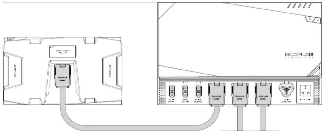
6.4 Connecting Batteries in Parallel
6.4.1 Charging and Discharging in Parallel
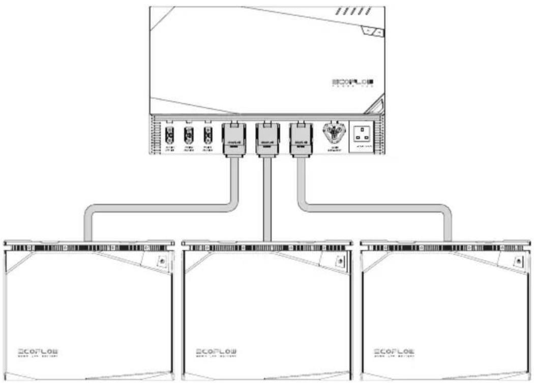
Connecting Batteries in Parallel via the EcoFlow Power Hub
The EcoFlow LFP Battery is a 48V battery system and only supports parallel connection. Up to three EcoFlow LFP Batteries can be connected to the EcoFlow Power Hub at the same time. The EcoFlow LFP Battery Power Cable has preset communication signal, allowing paralleled batteries to communicate with each other.
* Do not use the battery in series as this can potentially damage the battery.
- Ensure the battery is switched off before connection.
- Connect the battery to the EcoFlow Power Kits via the EcoFlow LFP Battery Power Cable as shown in the diagram below.
flowchart
graph TD
    A["ECOLO"] --> B["Device 1"]
    A --> C["Device 2"]
    A --> D["Device 3"]
    A --> E["Device 4"]
    B --> F["ECOLO Module 1"]
    C --> G["ECOLO Module 2"]
    D --> H["ECOLO Module 3"]
    E --> I["ECOLO Module 4"]
6.5 Battery Management System
The battery is equipped with a battery management system (BMS) and has the following battery protection features:
| Battery Discharging Low Voltage Protection | Prevents over-discharging of batteries |
| Battery Charging High Voltage Protection | Prevents over-charging of batteries |
| Battery Charging/Discharging Overheat Protection | Prevents high battery temperature |
| Battery Charging/Discharging Over-Current Protection | Prevents excessive battery current |
| Battery Equalization Function | Keeps each individual cell in the same condition to ensure the battery is in an optimal condition for use |
*When protection is triggered, disconnect the battery and leave it for some time before restarting it.
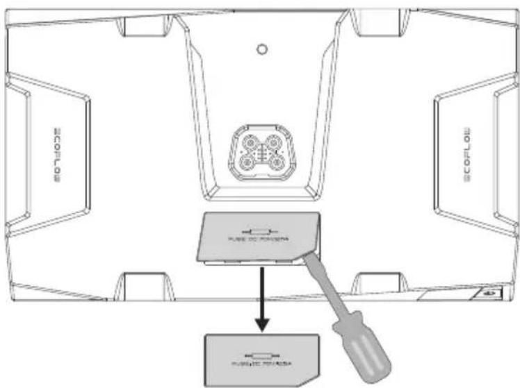
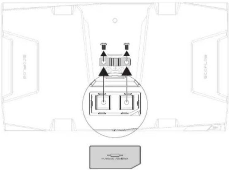
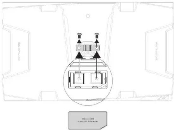
6.6 Replacing the Fuse
The EcoFlow 5kWh LFP Battery has a built-in DC 70V/150A replaceable fuse, while the 2kWh LFP Battery has a built-in DC 70V/125A replaceable fuse. Under normal operating conditions, there is no risk of fuse blowing. When an external short circuit occurs and the battery management system is not protected in time, the fuse will blow immediately to protect the battery. When a short circuit occurs and the battery cannot be charged or discharged, the fuse must be replaced. Replacement procedure is as follows:
- Ensure the battery is switched off, open the fuse cover using a suitable tool, and keep the cover in a safe place.
text_image
MONITOR SCOPOLO PLANE OF CANADORA PLANE OF CANADORA- Replace the fuse then install the cover back.
text_image
ECOFL ECOFL PLA123C 70768547. Battery Installation
Precautions
- After opening the battery package, first check the battery and accessories. If the battery is damaged or there is an occurrence of missing parts, please contact the vendor.
- Ensure the battery is switched off before installation.
- Make sure the electrical specifications of the battery are compatible with the relevant devices and systems.
- Keep the battery away from flame and liquid.
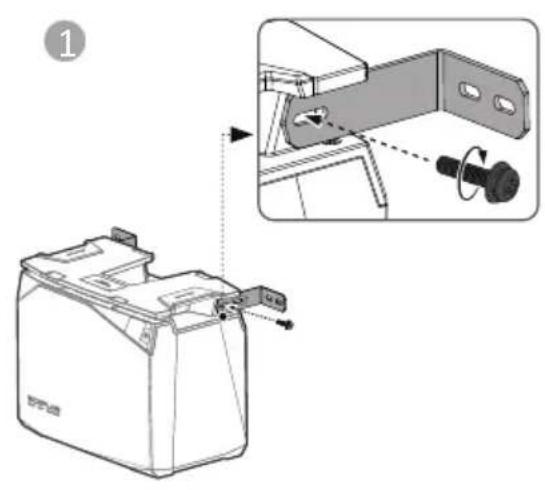
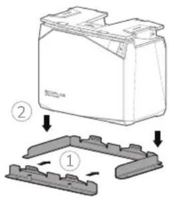
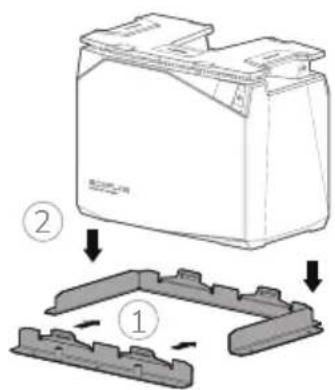
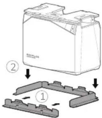
*In case of movement and vibration, such as in caravans and boats, the battery shall be fixed in the following three configurations to prevent the battery from falling over.
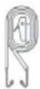
LFP Battery Mounting Bracket
text_image
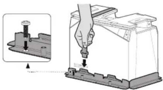
Technical diagram showing a battery component with an inset close-up of its internal structure, labeled with step number 1.
natural_image
Technical illustration of a battery holder with an inset showing the internal mechanism (no text or symbols present)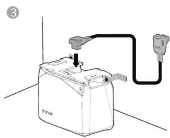
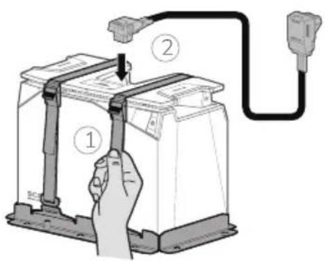
natural_image
Diagram of a battery connected to a plug, showing internal components and wiring (no text or symbols)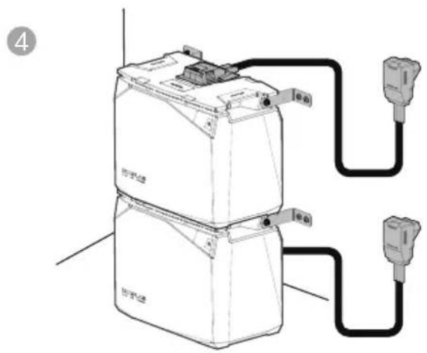
text_image
Diagram of a battery connected to two external power outlets, labeled with Chinese characters and electrical connections.
text_image
Diagram showing three stacked electronic devices connected to a multi-pin connector, with labeled ports and wiring connections.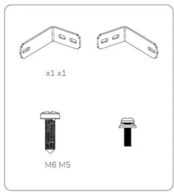
text_image
x1 x1 M6 M5LFP Battery Wall Mounting Clamp
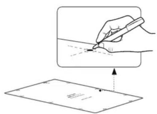
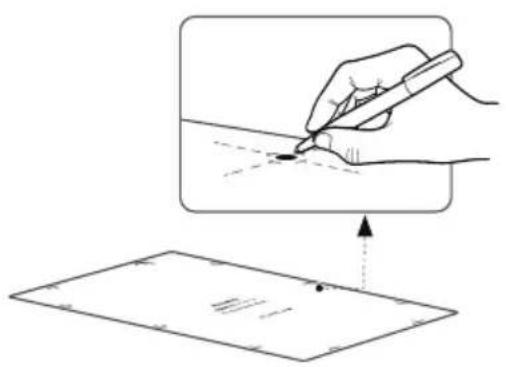
text_image
Diagram illustrating a hand holding a pen writing on paper, with an arrow indicating the process and a dotted line marking a reference point.1
text_image
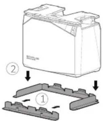
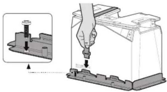
Diagram showing a battery casing with two components and a mechanical component, labeled with parts 1 and 2.2
text_image
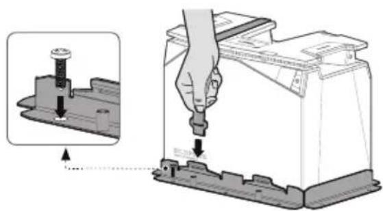
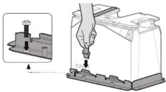
Diagram illustrating battery mounting process with magnified detail and instruction to press or adjust components3
text_image
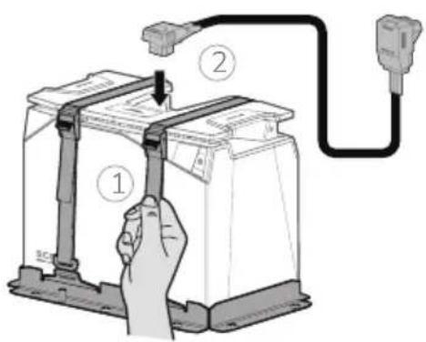
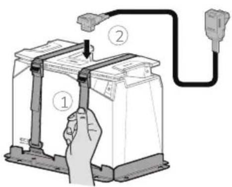
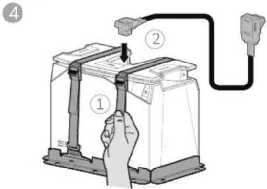
Diagram showing a hand holding a battery connected to a plug via cable, with labeled parts ① and ②.4

x1 x2 x2 x2 M6*20
8. Battery Maintenance and Disposal
8.1 Maintenance Instructions
- The battery must be stored in dry and well-ventilated environment. If the storage temperature is too high or too low, this will affect the self-discharge rate of the battery and accelerate the natural aging of the battery. It is therefore recommended to store the battery at a temperature of 20\~45°C (68°F\~113°F) and stay away from water sources, heat sources, and metal objects.
- If the battery is not going to be used for a long period of time, it is recommended to be stored intact in a semi-charged state (60% SOC). The battery is recommended to be discharged to 30% and then recharged to 60% every three months.
- For safety reasons, the battery must not be stored at temperature above 45^ C ( 113^ F) or below 20^ C ( 68^ F).
- When the temperature of battery is equal to or below -20^ ( -4^ ), the battery cannot be used for charging, discharging or heating.
- To extend the service life of the battery, the battery is recommended to be used at 20°C (68°F) to 45°C (113°F).
- If the battery level is below 1% after use, it should be charged to 60% before storage. If the battery is left idle for a long period of time with critically low SOC, irreversible damage to the battery cell will occur, reducing the service life of the battery.
- If the battery SOC is critically low and being left idle for too long, it will enter deep sleep mode and will need to be recharged before it can be used again.
8.2 Disposal
- If conditions permit, make sure that the battery is completely discharged before placing the battery in the designated battery recycling bin. The battery cells, which contain hazardous chemicals, are strictly prohibited from being placed in an ordinary garbage bin. For relevant details, please comply with the user's local laws and regulations regarding lithium battery recycling and disposal.
- If the battery cannot be fully discharged due to the fault of the product itself, do not dispose the battery directly. Contact a specialized battery recycling company for further disposal.
- An over-discharged battery cannot be switched on. Please dispose the battery according to local laws and regulations.
9. Troubleshooting
| Description of Error | Error Type | Recovery Methods | |
| [WD705] | Icon stays on | Low Temperature Indicator | Charging: Automatic recovery after battery temperature above 5°C (41°F)Discharging: Automatic recovery after core temperature above -17°C (1.4°F) |
 | Icon stays on | High Temperature Indicator | Charging: Automatic recovery after cooling to below 42°C (107°F)Discharging: Automatic recovery after cooling to below 52°C (125°F) |
| Over-Discharge Protection | Battery charging, automatic recovery when SOC >0% | ||
| Overcharge Protection | Charging stops and recovers automatically after partial consumption of battery power | ||
 | Icon flashing | Overload Protection | Remove the overpowered device and restart the machine to recover it |
| Short-Circuit Protection | Professional inspection recommended to eliminate the cause of the short circuit | ||
| Overcurrent Protection | Remove the overcurrent device and restart the machine to recover it | ||
10. Frequently Asked Questions
- What type of battery chemistry is used in this product?
This product uses high quality lithium iron phosphate.
- How do I clean the battery?
The battery can be wiped with a dry, soft, and clean cloth or tissue.
- Are lithium batteries safe?
The EcoFlow LFP Battery is protected by high-performance BMS and have undergone rigorous testings to ensure safety in use.
- Can the 5kWh LFP Battery and 2kWh LFP Battery be used in parallel?
This is not recommended — when using two models in parallel, the consistency of the batteries cannot be guaranteed, which can lead to shortened life span of the batteries or even a safety hazard.
- Can I charge the battery at low temperature?
Yes, when the battery is being charged at low temperature -20^ ≤ T ≤ 0^ ( -4^ ≤ T ≤ 32^ ), the charge heating function is switched on prior to heat the battery before it is charged normally.
- Can the battery be used with third-party power systems?
Yes, the user will need to perform extra wiring for this.
- How do I store the battery?
When storing the battery, first switch it off and then store it in a dry, ventilated place at room temperature and stay away from water sources.
- Can the battery be heated when charging with MPPT at ambient temperature below 0°C (32°F)?
Yes. Depending on the intensity of solar radiation and the power of the solar panel used by the user. It is recommended to connect to at least 400W of solar panel(s).
Haftungsausschluss
text_image
QR code with embedded logo containing 'EF' text and circular design elementsEcoFlow-App
text_image
ECOPLOE SILV 2018natural_image
Technical line drawing of two mechanical components with mounting holes (no text or symbols)Montageband

line
| Anzahl der Zyklen | 100%DDD | 80%DDD | 50%DDD | | ----------------- | ------- | ------ | ------ | | 0 | 100% | 100% | 100% | | 1000 | ~95% | ~95% | ~95% | | 2000 | ~90% | ~90% | ~90% | | 3000 | ~85% | ~85% | ~85% | | 4000 | ~80% | ~80% | ~80% | | 5000 | ~75% | ~75% | ~75% | | 6000 | ~70% | ~70% | ~70% | | 7000 | ~65% | ~65% | ~65% | | 8000 | ~60% | ~60% | ~60% | | 9000 | ~55% | ~55% | ~55% |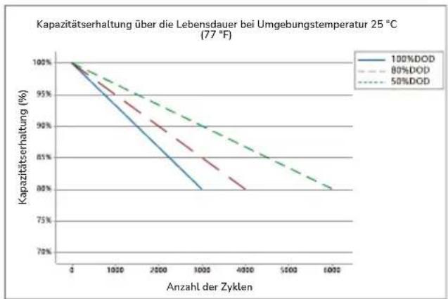
line
| Anzahl der Zyklen | 100%DOD | 80%DOD | 50%DOD | | ----------------- | -------- | ------- | ------- | | 0 | 100% | 100% | 100% | | 1000 | 95% | 94% | 93% | | 2000 | 90% | 88% | 86% | | 3000 | 85% | 82% | 80% | | 4000 | 80% | 78% | 76% | | 5000 | 78% | 76% | 74% | | 6000 | 76% | 74% | 72% |5.2 EcoFlow Power Kits
text_image
Diagram of a device interior with numbered components and labeled parts in Chinesenatural_image
Pure geometric diagram with shaded regions and dots, no text or symbols presenttext_image
ECOFLOW ECOFLOWtext_image
Technical diagram showing a battery housing with an inset close-up of its internal component and a close-up view of the switch mechanism.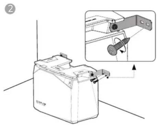
natural_image
Technical illustration of a battery holder with an inset showing mechanical assembly (no text or symbols)
natural_image
Diagram of a battery connected to a plug, showing wiring and grounding (no text or symbols)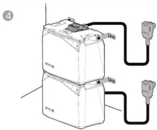
text_image
4 电源 电池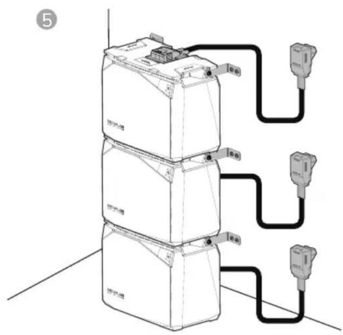
text_image
⑤
text_image
x1 x1 M6 M52. Application EcoFlow
text_image
QR code with embedded logo containing 'EF' text in the centerApplication EcoFlow
natural_image
Technical line drawing of two mechanical bracket components (no text or symbols)La courroie

line
| Nombre de cycles | 100%DD | 80%DD | 50%DD | | ---------------- | ------ | ----- | ----- | | 0 | 100% | 100% | 100% | | 1000 | 95% | 95% | 95% | | 2000 | 90% | 90% | 90% | | 3000 | 85% | 85% | 85% | | 4000 | 80% | 80% | 80% | | 5000 | 75% | 75% | 75% | | 6000 | 70% | 70% | 70% | | 7000 | 65% | 65% | 65% | | 8000 | 60% | 60% | 60% | | 9000 | 55% | 55% | 55% |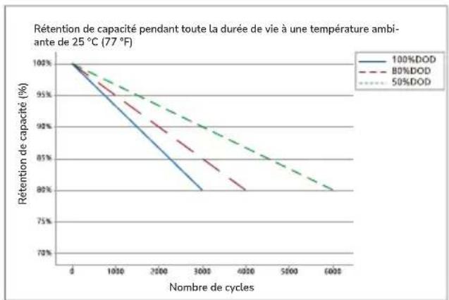
line
| Nombre de cycles | 100%DOD | 80%DOD | 50%DOD | | ---------------- | -------- | ------- | ------- | | 0 | 100% | 100% | 100% | | 1000 | 95% | 95% | 95% | | 2500 | 90% | 90% | 90% | | 3000 | 85% | 85% | 85% | | 4000 | 80% | 80% | 80% | | 5000 | 75% | 75% | 75% | | 6000 | 70% | 70% | 70% |Batterie LFP 5kWh Batterie LFP 2kWh
text_image
Diagram of a room layout with numbered components and directional arrows indicating movement or flow.natural_image
Pure diagram of a symmetrical mechanical or architectural component with no text, numbers, or symbolstext_image
ECOFLow ECOFLow ECOFLow ECOFLow ECOFLow ECOFLow ECOFLow ECOFLow ECOFLow ECOFLow ECOFLow ECOFLow ECOFLow ECOFLow ECOFLow ECOFLow ECOFLow ECOFLow ECOFLow ECOFLow ECOFLowtext_image
Technical diagram showing connection between an ECOFLOW device and its internal components with labeled ports and connectors.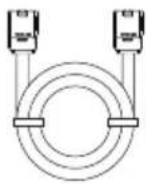
text_image
BICOPLO BICOPLO PLA100C 70V/86Atext_image
Technical diagram showing a battery component with an inset close-up of its internal structure, labeled with number 1 and Chinese characters.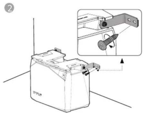
natural_image
Technical illustration of a battery casing with an inset showing a mechanical component being inserted (no text or symbols present)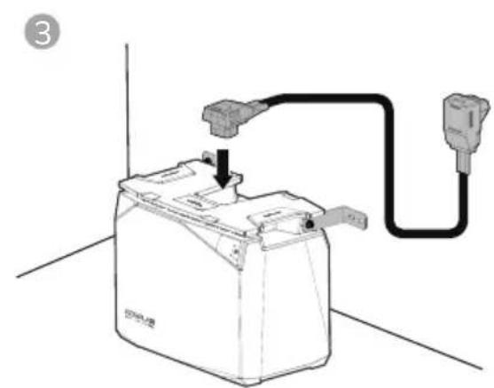
natural_image
Line drawing of a battery connected to a plug, showing internal components and wiring (no text or symbols)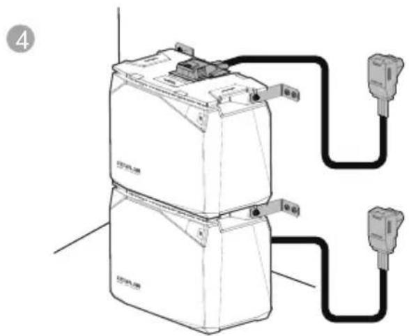
natural_image
Diagram of a battery connected to two external sensors (no text or symbols present)
text_image
Diagram showing three stacked battery units connected to three connected outlets with labeled ports and connections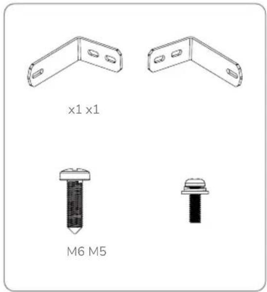
text_image
x1 x1 M6 M5text_image
Diagram illustrating a hand holding a pen writing on paper, with an arrow indicating the process and a dotted line marking a reference point.1
text_image
Diagram showing a battery component with two labeled parts (① and ②) indicating assembly steps.3
text_image
Diagram showing a hand using a tool to adjust or install a battery component, with an inset close-up highlighting the component's adjustment.2
4
text_image
Diagram showing a hand holding a battery connected to a power outlet via cable, with labeled parts 1 and 2.
x1 x2 x2 x2 M6*20
https://download.ecoflow.com/app
text_image
QR code with embedded logo containing 'EF' text in the centerApp EcoFlow
natural_image
Technical line drawing of two mechanical bracket components (no text or symbols)line
| Numero di cicli | 100%DOD | 80%DOD | 50%DOD | | --------------- | -------- | ------- | ------- | | 0 | 100% | 100% | 100% | | 1000 | ~95% | ~93% | ~92% | | 2000 | ~90% | ~88% | ~86% | | 3000 | ~85% | ~83% | ~82% | | 4000 | ~80% | ~78% | ~78% | | 5000 | ~75% | ~73% | ~73% | | 6000 | ~70% | ~68% | ~68% |5.2 EcoFlow Power Kits
text_image
Diagram of a device layout with numbered components and directional arrows indicating flow or movement.natural_image
Top-down schematic of a symmetrical mechanical or architectural component with shaded sections and bolt holes (no text or symbols)text_image
ECOFLow ECOFLow ACI 10 200 MB PVC 10 ACI 10 PVC 10 Battery Battery Battery Battery Battery ECOFLow ECOFLow ECOFLow ECOFLow ECOFLow ECOFLow ECOFLow ECOFLowtext_image
Technical diagram showing a battery mounting mechanism with an inset close-up of the component being adjusted.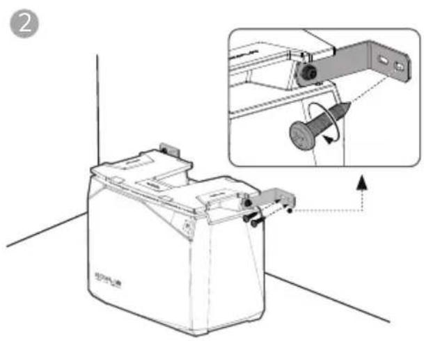
natural_image
Technical illustration of a mechanical device with an inset showing a mechanical component being inserted (no text or symbols present)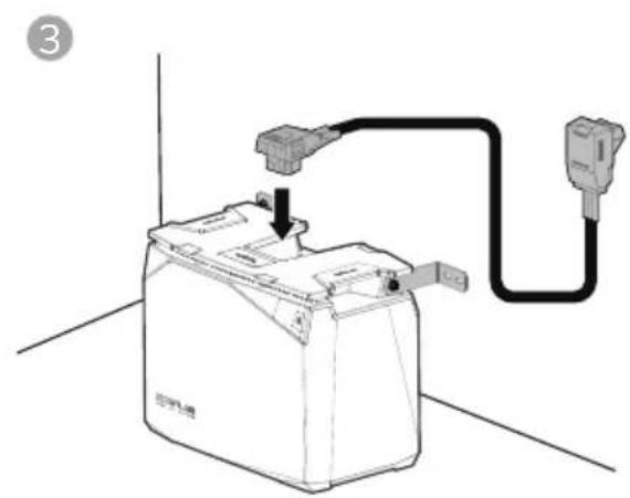
natural_image
Diagram of a battery connected to an electrical outlet via a cable, showing wiring and grounding (no text or symbols)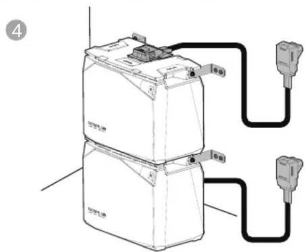
text_image
Diagram of an electrical device with labeled components and wiring connections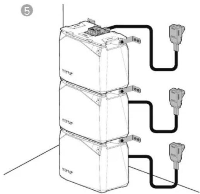
natural_image
Diagram of three stacked electronic devices connected by wires, no text or symbols present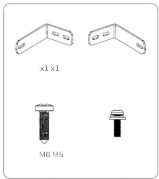
text_image
x1 x1 M6 M5text_image
QR code with embedded logo containing 'EF' text in the centerAplicación EcoFlow
3. Componentes
text_image
SCOPL00 B21.00 2004natural_image
Technical line drawing of two mechanical components with mounting holes (no text or symbols)text_image
Diagram of a room layout with numbered compartments and labeled areas, including a central circular object and directional arrows.natural_image
Pure geometric diagram with shaded regions and dots, no text or symbols presenttext_image
ECOFLow ECOFLow ECOFLow ECOFLow ECOFLow ECOFLow ECOFLow ECOFLow ECOFLow ECOFLow ECOFLow ECOFLow ECOFLow ECOFLow ECOFLow ECOFLow ECOFLow ECOFLow ECOFLow ECOFLow ECOFLowtext_image
Technical diagram showing connection between an internal device and an external network device labeled 'ECOPLOW'.
text_image
COLOE COLOE FUSÉ DU FUMÍNDA FUSÉ 00 70V/86Atext_image
Technical diagram showing a battery component with an inset close-up of its internal structure and rotation direction.
natural_image
Technical illustration of a battery casing with an inset showing a mechanical component (no text or symbols)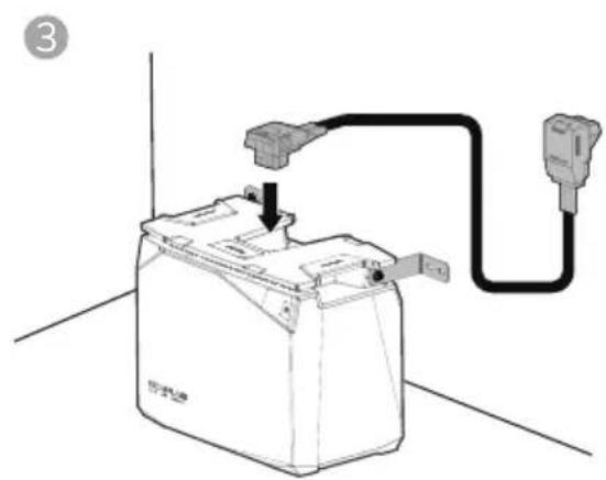
natural_image
Line drawing of a battery connected to a plug, showing wiring and grounding (no text or symbols)
natural_image
Diagram of a battery connected to two external power outlets (no text or symbols present)
text_image
Diagram showing three stacked electronic devices connected to a multi-pin connector, with labeled ports and wiring connections.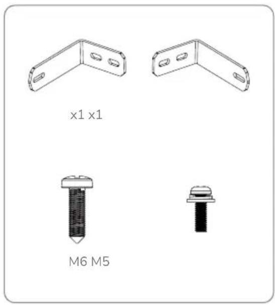
text_image
x1 x1 M6 M5text_image
Diagram illustrating a hand holding a pen writing on paper, with an arrow indicating the process and a dashed line suggesting alignment or annotation.1
text_image
Diagram showing a battery casing with two labeled parts (① and ②) illustrating the assembly process.2
natural_image
Diagram showing a hand inserting a plug into a battery pack, with an inset close-up of the component (no text or symbols present)3
text_image
Diagram showing a hand holding a battery connected to a power outlet via cable, with labeled parts 1 and 2.


x1 x2 x2 x2 M6*20
text_image
QR code with embedded logo and Chinese text 'TECH' in the center
text_image
QR code with embedded logo and text, likely for digital scanning and linking to online contentEcoFlow APPEcoFlow 官方微信
natural_image
Pure architectural or engineering line drawing without any text, numbers, or symbols磷酸铁锂电池
电池连接线
用户手册和保修卡 固定角铁
螺钉
natural_image
Technical line drawing of two mechanical components with mounting holes (no text or symbols)电池平置绑带套件
4. 电池规格
4.1 基本参数
text_image
Diagram of a room layout with numbered compartments and labeled areas, including a central circular object and directional arrows.顶部底部
natural_image
Pure geometric diagram with shaded regions and dots, no text or symbols present- 保险丝盖
- 绑带固定缺口
- 底部堆叠缺口
text_image
ECOFLOW ECOFLOW侧面数字显示屏
text_image
Diagram showing network connection between a device and an ECOFLOW device, with labeled ports and connections.text_image
Technical diagram showing connection between an internal device and an ECOFLOW PLC module with labeled ports and wiring.text_image
Technical diagram showing a device with labeled ports and a control panel, likely for installation or inspection.- 更换新保险丝,然后装回盖板。
text_image
ECOPLC08 ECOPLC08 E-50 DE 240V7. 电池安装
注意事项
text_image
Technical diagram showing a battery component with an inset close-up of its internal structure and a close-up view of the switch mechanism.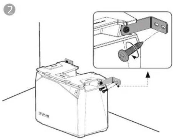
text_image
Technical diagram showing a device with an inset close-up of its internal structure, labeled with Chinese text and directional arrows.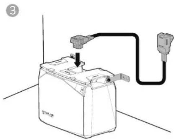
natural_image
Line drawing of a battery connected to a plug, showing wiring and grounding (no text or symbols)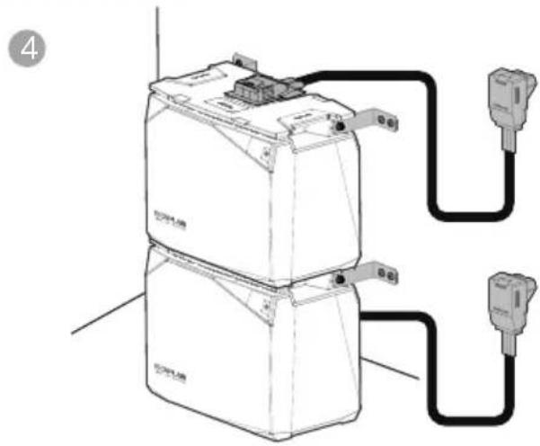
natural_image
Line drawing of a battery connected to two external power outlets (no text or symbols present)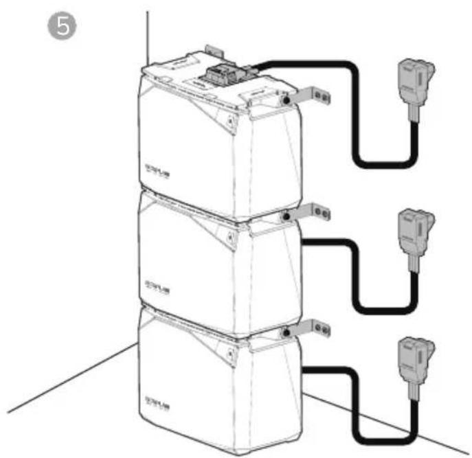
text_image
⑤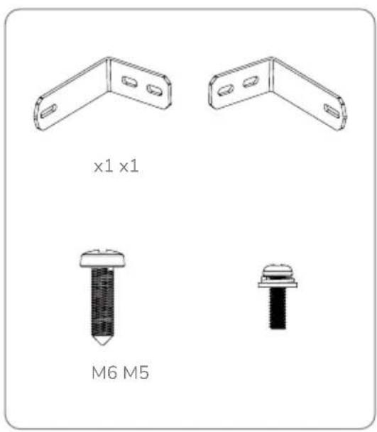
text_image
x1 x1 M6 M5电池堆叠固定套件
text_image
Diagram illustrating a hand holding a pen writing on paper with an arrow indicating direction of movement or alignment.1
text_image
Diagram showing a battery component with two labeled parts (① and ②) indicating assembly steps.2
text_image
Diagram showing a hand using a tool to adjust or install a battery component, with an inset close-up highlighting the component's adjustment.3
text_image
Diagram showing a hand holding a battery connected to a plug via cable, with labeled parts ① and ② indicating components.

x1 x2 x2 x2 M6*20