FSH 402 ID TS BK - Cooker Fulgor Milano - Free user manual and instructions
Find the device manual for free FSH 402 ID TS BK Fulgor Milano in PDF.

User questions about FSH 402 ID TS BK Fulgor Milano
0 question about this device. Answer the ones you know or ask your own.
Ask a new question about this device
Download the instructions for your Cooker in PDF format for free! Find your manual FSH 402 ID TS BK - Fulgor Milano and take your electronic device back in hand. On this page are published all the documents necessary for the use of your device. FSH 402 ID TS BK by Fulgor Milano.
USER MANUAL FSH 402 ID TS BK Fulgor Milano
natural_image
Four black circles arranged in a 2x2 grid on white background (no text or symbols)FSH 604 ID TS
FSH 402 ID TS
PIANI INDUZIONE
INDUCTION SURFACE
PLAN A INDUCTION
INDUKTIONSHERD
flowchart
graph TD
    A["A"] --> B["B"]
    B --> C["C"]
    C --> D["D"]
    D --> A
    style A fill:#fff,stroke:#000
    style B fill:#fff,stroke:#000
    style C fill:#fff,stroke:#000
    style D fill:#fff,stroke:#000
    note right of A "FULCOR"
    note left of A "-
+"
    note right of C "-
I 0 II - +"

text_image
8 3 u 8 3 u 8.88 - 3 + i 0 11 8.3 u 8.3 unatural_image
Line drawing of a hand using a tool to clean or paint (no text or symbols)text_image
280 +1 0 R 5 MAX 467 +1 0Fig. 8 - FSH 604 ID TS Fig. 8 - FSH 402 ID TS

text_image
400V 2N~ N L2 L1 5 4 3 2 1 230V~ N L 5 4 3 2 1
text_image
~230V LNDear Customer,
we would like to thank you and congratulate you on your choice.
This new product has been carefully designed and built using top quality materials, and meticulously tested to ensure that it meets all your culinary requirements.
Please read and observe these simple instructions, which will enable you to achieve excellent results from the very first time you use it. This state-of-the-art appliance comes to you with our very best wishes.
THE MANUFACTURER

ATTENTION
THIS PRODUCT IS DESIGNED FOR DOMESTIC USE.
THE MANUFACTURER DECLINES ALL RESPONSIBILITY FOR DAMAGES TO THINGS OR PEOPLE DERIVING FROM INCORRECT INSTALLATION OR IMPROPER, ERRONEOUS OR UNSUITABLE USE.
THE APPLIANCE MUST NOT BE USED BY PEOPLE (INCLUDING CHILDREN) WITH PHYSICAL, SENSORIAL OR MENTAL IMPAIRMENTS, OR BY PEOPLE WITHOUT THE NECESSARY EXPERIENCE OR KNOWLEDGE, UNLESS THEY ARE SUPERVISED OR INSTRUCTED IN THE USE OF THE APPLIANCE BY A PERSON RESPONSIBLE FOR THEIR SAFETY.
CHILDREN MUST BE SUPERVISED TO ENSURE THAT THEY DO NOT PLAY WITH THE APPLIANCE.
INDEX PAGE
1 - Operating principle 2
Induction 2
Operating principle 2
2 - User instructions 3
Installation 3
Use 3
Pan detection 3
Residual heat indicator 5
Protection in the event of accidental switching on 5
Key LoPrecautions 5
Pans 6
Maintenance 6
Turning the cooking surface on and off 6
Acoustic signal (buzzer) 6
Turning on a cooking area 6
Turning off a cooking area 6
Power level 6
Booster and power management 6
Automatic preheating (or "heat-up" function) 7
Activating automatic heating (or "heat-up" function) 7
Extension function (For large pans) 7
Special functions 7
Control lock (child safety) 7
Unlocking/deactivation child safety 7
Key 7
Pause 7
Deactivating Pause 8
Timer function 8
Independent timer 8
Turning off/changing the timer 8
Programming the timer for the cooking areas 8
3 - Installation instructions 10
Installation 10
Positioning 10
Electrical connection 10
Induction
Heating by induction is the most efficient form of cooking available. The heat is generated by an electromagnetic field, directly on the bottom of the pan or pot used.
The surface which is free from contact remains virtually cold. When the cooking time is up and the container is removed, there is no residual heat. It is efficient become there is no waste of energy due to dispersion, as happens with gas burners, it is 30 to 50% faster than normal hobs using HGL technology and allows energy savings of up to 25%.
If liquid overflow from the container, it does not stick to the surface of the hob, because this is just slightly warm.
Operating principle
This is based on the electromagnetic properties of most cooking containers.
The electronic circuit governs the operation of the coil (inductor), creating a magnetic field.
The heat is transmitted by the container to the food.
Te cooking process takes place as follows:
• minimum dispersion (high performance);
- the removal of the pan (simply lifting it) automatically stops the system;
- the electronic system allows maximum flexibility and precision of regulation.
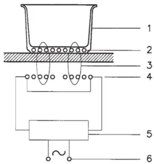
Fig. 1
text_image
1 2 3 4 5 61 - Recipient
2 - Induced current
3 - Magnetic field
4 - Inductor
5 - Electronic circuit
6 - Electricity supply
Installation
All installation operations (electrical connection) must be carried out by people qualified in compliance with the laws in force.
For specific instructions, see the installation section.
DO NOT FOCUS INENSEL ON THE LEDS AND DISPLAYS.
Use
First of all, position the pan in the chosen cooking area.
The absence of the pan display y means the system cannot start.
Pan detection
A certainty which distinguishes the knowledgeable use of technology in favour of the consumer.
Fig. 2 - FSH 604 ID TS
flowchart
graph TD
    A["Path A"] -->|→| B["Path B"]
    B -->|←| D["End"]
    A -->|→| C["End"]
    style A fill:#f9f,stroke:#333
    style B fill:#ccf,stroke:#333
    style C fill:#cfc,stroke:#333
    note right of A: "FULGOR\nMLAIC"
    note right of C: "+"
    note right of D: "I 0 II"
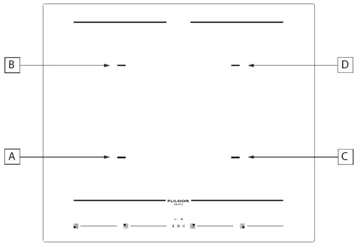
A: INDUCTION COOKING ZONE 220x180 2100/3700 W
B: INDUCTION COOKING ZONE 220x180 2100/3700 W
C: INDUCTION COOKING ZONE 220x180 2100/3700 W
D: INDUCTION COOKING ZONE 220x180 2100/3700 W
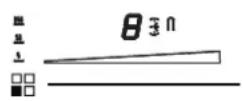
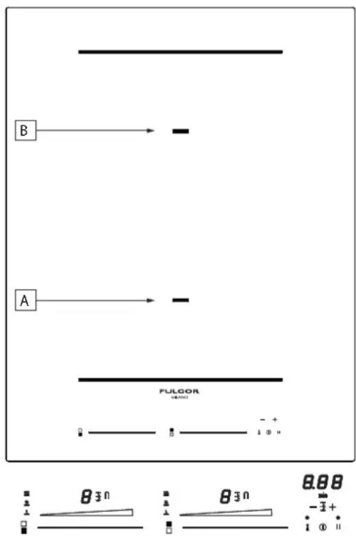
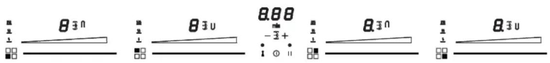
Fig. 2 - FSH 402 ID TS

1 ON/OFF
2 + TIMER
3 - Timer
4 Key on LED
5 Key on button
6 Pause on button
7 Pause and Recall involuntary switch-off LED
8 Heating area and special function activation indicator
9 Minimum level activation cursor area
10 Maximum level activation cursor area
11 Power Booster (P) activation cursor area
12 Extension function on icon
13 Timer for cooking area activation icon
14 Cooking area level display
15 Cooking level illuminated bar
16 Melt function symbol
17 Heating function symbol
18 Simmering function symbol
19 Timer (minutes/seconds) display
20 Timer (minutes/seconds) display
21 Separator dot (hours/minutes)
22 Timer display (hours/minutes)
23 Icon indicating minutes
24 Independent timer icon
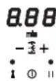
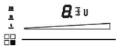
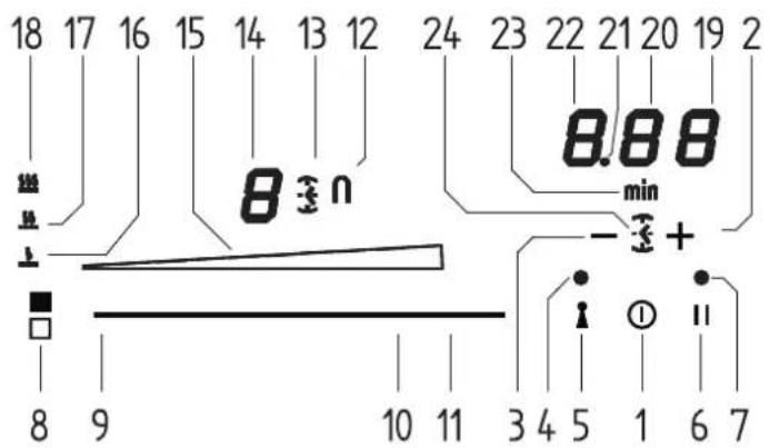
Fig. 3 - FSH 402 ID TS
text_image
18 17 16 15 14 13 12 24 23 22 21 20 19 2 8 3 n 8.88 min - 3 + 8 9 10 11 3 4 5 1 6 71 ON/OFF
2 + TIMER
3 - Timer
4 Key on LED
5 Key on button
6 Pause on button
7 Pause and Recall involuntary switch-off LED
8 Heating area and special function activation indicator
9 Minimum level activation cursor area
10 Maximum level activation cursor area
11 Power Booster (P) activation cursor area
12 Extension function on icon
13 Timer for cooking area activation icon
14 Cooking area level display
15 Cooking level illuminated bar
16 Melt function symbol
17 Heating function symbol
18 Simmering function symbol
19 Timer (minutes/seconds) display
20 Timer (minutes/seconds) display
21 Separator dot (hours/minutes)
22 Timer display (hours/minutes)
23 Icon indicating minutes
24 Independent timer icon
Residual heat indicator
this tells the user that the glass is at a dangerously high heat in case of contract with the whole area over the cooking zone. The temperature is determined using a mathematical model and any residual heat is indicated with an "H" by the corresponding seven-segment display.
Heating and cooling are calculated in relation to:
• the power level selected (from "0" to "9");
• the relay activation period.
After switching off the cooking zone, the corresponding display shows an "H" until the temperature in the zone falls below the critical level ( ≤ 60^ ) in compliance with the mathematical model.
Protection in the event of accidental switching on
- If the electronic control sense continuous activation of a key for about 10 sec. it switches off automatically. The control gives off an acoustic error signal for 10 seconds, warning the user of the presence of an object on the sensors. The displays show the permanent error code, which will be displayed as long as the electronic control senses the error. If the cooking zone "burns", an "H" will appear on the display, alternating with the error signal.
• If no cooking zone is activated within 20 seconds of switching
on the touch control, the control returns to stand-by mode. (See also paragraph 1.2.
- When the touch control is on, the ON/OFF key takes priority over all the other key, so the touch control can be switched off at any time, even in the case of multiple or continuous activation of the keys.
- In stand-by mode, continuous activation of the keys will have no effect. However, before the electronic control can be switched on again, it must acknowledge that no key is active.
Key LoPrecautions
- If there is even the tiniest crack in the ceramic glass surface, immediately disconnect the hob from the electricity supply;
• during operation, move any magnetic materials such as credit cards, computer disks, calculators, etc., away from the area; - never use cooking foil or rest products wrapped in foil directly on the hob;
- metallic objects such as knives, forks, spoons and lids must not be rested on the surface of the hob to prevent them from heating up;
- with cooking with non-stick containers, without using water or oil, limit any preheating time to one or two minutes;
- when cooking foods which tend to stick to the bottom of the pan,
start at minimum power and gradually increase the heat, stirring frequently;
- after use, switching off correctly (decreasing to "0") and avoid relying on the pan sensor.
Pans (Fig. 4)
- If a magnet is attracted by the bottom of a container, the container is suitable for induction cooking;
- prefer pans declared as suitable for induction cooking;
- flat, thick-bottomed pans;
- a 20 cm diameter saucepan can benefit from maximum power;
- a small saucepan reduces the power but will not cause energy dispersion. The use of containers with a diameter of less than 12 cm is not recommended;
- stainless steel containers with multilayer bottom or ferrite stainless steel if the bottom indicates: for induction;
- cast iron containers, better with an enamelled bottom to avoid scratching the ceramic glass hob;
- containers made of glass, ceramic, terracotta, aluminium, copper or non-magnetic stainless steel (austenitic) are not recommended and are unsuitable.
Fig. 4
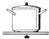
No
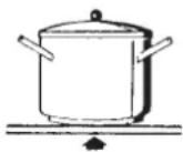
No
Yes
Maintenance (Fig. 5)
Traces of foil, food residues, splashes of fat, sugar or very sugary foods must be removed immediately from the hob using a scraper to avoid damaging the hob surface.
Then clean with SIDOL or STANFIX and kitchen paper, rinse with water and dry with a clean cloth.
Never use abrasive sponges or clothes and avoid using aggressive chemical cleansers such as OVEN SPRAYS or STAIN REMOVERS.
DO NOT USE STEAM CLEANERS
Fig. 5

natural_image
Simple line drawing of a hand using a tool to clean or paint particles from a surface (no text or symbols)Turning the cooking surface on and off
The cooking surface is turned on by pressing the "centre" On/Off button (1), you will hear a short beep and the 5 seven-segment displays light up showing "0".
If a cooking zone is "hot", the display will alternate between "H" and "O".
After switching on, the touch control remains active for 10 seconds. If you do not select either a cooking zone or the times, the touch control automatically returns to stand-by mode.
Acoustic signal (buzzer)
During use, the following activities are signalled by a buzzer:
- Normal pressing of the buttons with a short beep.
- Holding down buttons for more than 10 seconds with a long intermittent sound (an error symbol is displayed and, if you continue, the touch control is turned off)
Turning on a cooking area
Position a pot and touch an area of the cursor for the cooking area where the pot is (9-10-11), slide your finger to the right to increase the cooking level (10), or slide your finger to the left to decrease it (9).
Turning off a cooking area
A single cooking area can be turned off directly by selecting the "0" position by sliding your finger to the left in the cursor area for the cooking area that is working.
Hot cooking areas will be displayed with a letter "H".
You can turn off all cooking areas immediately at any time using the power On/Off button (1).
If, during cooking, you inadvertently turn off the surface while using the controls, you can turn it on again with the On/Off button and you will have 6 seconds to press the pause button (4) that will be indicated by the (3) flashing of an indicator light above the button; doing so will turn the surface on again with the same settings it had before it was accidentally turned off.
Power level
The power level of the cooking area can be set from level 1 to level 9. A further level P (Power Booster) is available that allows a very rapid heating of food and, therefore, saves you time.
The power level represented by an intermittent letter "A" is the activation of the automatic heating function.
Booster and power management
The generator, with Booster enabled, provides the cooking area power that is significantly higher than the rated power; the display of the selected cooking area shows a "P". The Booster function can be activated by pressing at the end of the cursor of the cooking area (11).
The power increase is different depending on the size of the cooking area:
For a rectangular cooking area (220x190), the power goes from a level 9 of 2100 W to the Booster level of 3700 W for 10 minutes.
For safety reasons, the Booster function has a limited duration.
If during pot is removed from the cooking area during the Booster time, the Booster remains active and the Booster time is not
deactivated.
With the Booster activated, changing the value set with your finger in the cursor area deactivates the Booster.
The Booster function "P" can be activated in all cooking areas, but priority is given to the last Booster activated, reducing any other cooking levels.
Automatic preheating (or "heat-up" function)
This feature makes cooking easier. You do not need to be permanently present during cooking: the surface automatically heats up at Full Power and then returns to the selected power level after a certain time (see Table 1).
Activating automatic heating (or "heat-up" function)
Press and hold an area of the cursor for the cooking area that is working for about 3 seconds until you hear a beep (such as 1/3 of the length of the cursor area).
For example: Select level 3 and activate the automatic heating function by pressing your finger for 3 seconds. The corresponding display shows the letter "A" alternating with "3". With these settings, the cooking surface heats the cooking area at the maximum level "9" for 2 minutes and then continues cooking level at level "3".
| Power Level | Duration Automatic Heating Function (time in minutes) | Maximum Duration of Working Time without Commands (time in minutes) |
| 0 | - | |
| 1 0' 40" 516 | ||
| 2 1' 12" 402 | ||
| 3 2' 318 | ||
| 4 2' 56" 258 | ||
| 5 4' 16" 210 | ||
| 6 7' 12" 138 | ||
| 7 2' 138 | ||
| 8 3' 12" 108 | ||
| 9 - | 90 | |
| P | - | 10 |
Extension function (For large pans)
This function facilitates cooking with large rectangular pans, is only available for the rectangular cooking areas and is activated by simultaneously pressing the 2 cursors of the 2 cooking areas involved. At this point, a "U" icon will light up next to the display of the levels (1-9) and the cooking area can now be controlled from only once cursor since the other will work simultaneously at the same level.
Special functions
By turning on the touch display, you can program a special function by pressing the button indicating the position of the cooking area (button 8).
This function is available to "assist cooking" in each cooking area and is indicated by one of the three dedicated icons.
It is possible to activate 3 "cooking" levels:
1) Melting with a temperature of approximately 42 °C.
2) Heating with a temperature of approximately 70^ C.
3) Simmering with a temperature of approximately 94 °C.
These temperatures are approximate and are greatly dependent on the pot and the quantity of food.
Control lock (child safety)
It is only activated when the cooking surface is on but no cooking area is on.
Simultaneously press the key button (5) and the pause button (6) and then press the key button (5).
The letter "L" will appear on both displays for 10 seconds and then they will turn off.
When you try to turn on the cooking surface with the On/Off button (1), the letters "L" will be displayed and it will not be possible to cook.
Unlocking/deactivation child safety
There are two types of unlocking:
1) Unlocking for one time only: To disable the function, turn on the cooking surface and simultaneously press the pause (6) and key (5) buttons. The letters L disappear and are replaced by a "0" for each cooking area. If you turn off the cooking surface after use, when it is turned on again, the letters L will be displayed to indicate that the surface is locked.
2) Permanent unlocking: To disable the function permanently, turn on the cooking surface and simultaneously press the pause (6) and key (5) buttons. Then release these 2 buttons and press the Pause button (6) again.
Key
This cooking surface allows setting a keypad lock using the lock button (5). It may be useful to lock the keypad during operation, for example for cleaning the control area or, in any case, if you do not want to change any settings.
The On/Off button (1) still has priority.
Pause
This cooking surface allows setting a pause (6) during cooking (which is useful, for example, when answering a phone call). When this function is pressed, an LED lights above the button and the symbol "II" is displayed in all the cooking areas and the cooking settings and timers are frozen for a maximum of 10 minutes, after which the cooking surface turns off.
Deactivating Pause
Once activated, the function can be deactivated by pressing the pause button (6) again. The LED for the pause setting turns off and, within 10 seconds, you must slide your finger along the cursor below the illuminated area (from left to right). This allows the surface to resume cooking and the timer starts from the same point at which it was stopped.
Timer function
There are two versions of the timer function:
- An independent timer from 1 to 59 minutes: it beeps when the time has run out. This function is always available and is indicated by the clock symbol (24) which is located between the - and + buttons (the symbol may be less bright if another cooking area timer has a remaining time that is less than that set on the independent timer).
- A timer from 1 to 59 minutes for each cooking area: it beeps when the time has run out and turns off the cooking area where it was set. The 4 cooking areas can be programmed independently (the symbol may be less bright if another cooking area timer has a remaining time that is less than that set on the independent timer).
The type of timer activated is shown in the dedicated displays (19-20-21-22). The timer with the least time is highlighted and the related clock icon is brighter (13-24). The other timer settings are still active and running, but the clock icon (13-24) will be less bright. Another icon with the word "min" (23) appears when you set times longer than 10 minutes. For example 0.11 indicates 0 hours and 11 minutes.
The separator dot (21) flashes when the timer is running, while the dot is static while the timer is selected and thus modifiable.
Independent timer
- If the touch display is on, the independent timer can be used by simultaneously pressing the + and - buttons. If all the cooking areas are in position "0", this is the only timer available. The clock icon (24) will turn on and the display will show "0.00". If you do not select any button, the timer deactivates within 5 seconds.
- The time setting (0-1 hour.59 min) can be changed in increments of one minute with the + button from 0 to 99.
- Holding down the + or - button dynamically increases the rate of change up to a maximum value, without beeps.
- If the + (or -) button is released, the rate of increase (decrease) starts again from the initial value.
- The timer can be set by either continuously pressing the + or - buttons or by pressing successively (with beeps).
After the timer is set, it begins to count down. The expiry of the time is signalled by a beep or by the flashing of the timer display, which will show "00".
The beep will not stop until the + or - button is pressed. The display stops flashing and turns off.
Turning off/changing the timer
- The timer can be changed or turned off at any time by turning on the touch display again, if no cooking area is on, and pressing the + and - buttons simultaneously to select the timer. At this point, set it to "0" by pressing the - button, to turn it off, or by pressing the + button to increase the time setting.
- The independent timer remains active even when the On/Off button is pressed
Programming the timer for the cooking areas
By turning on the touch display, you can program an independent timer for each cooking area.
- At least one cooking area must be on and set to a certain level.
- By pressing the + and - buttons simultaneously, you can set a countdown for turning off the cooking area. There are illuminated clock icons (13) next to the display of the cooking area. To set the timer on a cooking area when there are more than one cooking area on, you must press the + and - buttons simultaneously. You will note that the clock icon will light and move to the various cooking areas each time you simultaneously press the + and - buttons.
- When the timer of the cooking area is selected, the related clock icon near the display becomes brighter (13). The timers programmed for each cooking zone remain active.
- Other functions of the timer are the same as the independent timer. To increase the time, use the plus button.
- The expiry of the time is signalled by a beep and "00" on the display and the LED of the cooking area assigned to the timer flashes. The cooking area is turned off and an "H" is shown if the area is "hot", otherwise the display shows a hyphen. The beeping and flashing of the display stop.
• Automatically after 2 minutes. - When you press the + or - buttons, the timer display turns off.
Error codes are displayed by the 7-segment display with "E" or "ER" plus the error number.
| Error message | Description Possible error reason Troubleshooting | ||
| "flash" | Permanent use of keys; Control unit cuts off after 10 sec | Water or cooking utensils on the glass above the control unit | Cleaning of the operational surface |
| Er 22 Defective Key evaluation. Control unit cuts off after 3.5 – 7.5 sec. | Short-circuit or discontinuation in the range of the key evaluation | Exchange control unit | |
| Er20 Flash-failure μC- faulty Exchange control unit | |||
| Er36 NTC value is not within its specification (value < 200mV or >4.9V; control unit cuts off | Short-circuit or cut-off at NTC Exchange control unit | ||
| Er31 Configuration data incorrect Configuration of induction necessary New Configuration | |||
| Er47 Communication error between TC and induction | None or faulty communication! Ensure that connection cable is plugged on correctly and functional. | ||
| E2 Overheating of the induction coils | Cooling down necessary | ||
| U400 | Secondary voltage of the power unit to high (primary >300V). Control unit cuts off after 1 sec releasing a permanent tone. | Control unit is wrongly connected. | Connect to correct mains voltage |
| E5 Error on filter board | Exchange filter board | ||
| E6 Error on power unit | Exchange power unit | ||
| E9 Coil temperature sensor defective | Exchange temperature sensore | ||
Installation
these instructions are aimed at qualified fitters as a guide to installation, adjustment and maintenance in compliance with the laws and standards in force. The operations must always be carried out with the appliance disconnected from the electricity supply.
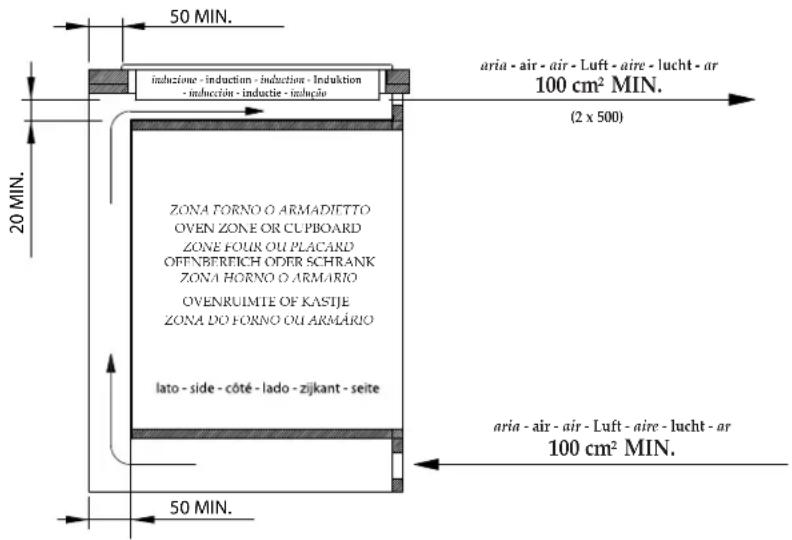
Positioning (Fig. 6-7)
The appliance is made to be fitted into a counter top, as shown in the figure. Apply the sealant supplied around the whole perimeter of the hob. Installation over an oven is not recommended, but if this is necessary, check that:
• the oven has an efficient cooling system;
• there is no passage of hot air from the oven to the hob;
- allow air passages as shown in the figure.
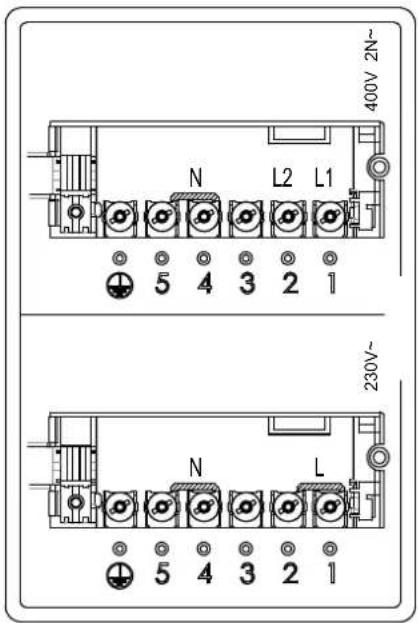
Electrical connection (Fig. 8)
Before connecting to the electricity supply, ensure that:
- the characteristics of the system are such as to satisfy that indicated on the registration plate applied to the bottom of the hob;
- the system has an effective earth connection compliant with the standards and laws in force. Connection to earth is compulsory by law.
If the appliance has no cable and/or plug, use material suitable for the absorption indicated on the registration plate and for the working temperature. The cable must not reach a temperature higher than 50^ C above room temperature in any point.
For direct connection to the network it is necessary to fit an omnipolar switch of a suitable size to ensure disconnection of he network with a contact opening distance that allows complete disconnection in the conditions of the overtension category III, compliant with the installation regulations (the yellow/green earth wire must not be interrupted).
The omnipolar socket or switch must be easy to reach when the appliance is installed.
N.B.:
- The manufacturer declines all responsibility if the usual accident prevention standards and the above instructions are not observed.
If the power cable is damaged, it must be replaced by the manufacturer or by the manufacturer's technical servicing network, or by a similarly qualified operator, to prevent every possible risk.
Fig. 6
text_image
50 MIN. induzione - induction - induction - Induktion - induktion - industrie - induzione 20 MIN. aria - air - air - Luft - aire - lucht - ar 100 cm² MIN. (2 x 500) ZONA FORNO O ARMADIETTO OVEN ZONE OR CUPBOARD ZONE FOUR OU PLACARD OFFNBERFICH ODER SCHRANK ZONA HORNO O ARMARIO OVENRUIMTE OF KASTIJE ZONA DO FORNO OU ARMARIO lato - side - côté - lado - zijkant - seite 50 MIN. aria - air - air - Luft - aire - lucht - ar 100 cm² MIN.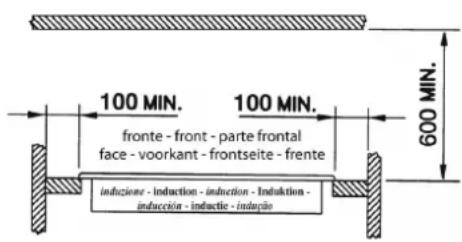
text_image
100 MIN. fronte - front - parte frontal face - voorkant - frontseite - frente induzione - induction - induction - Induction - induction - induction - induction - induction 600 MIN.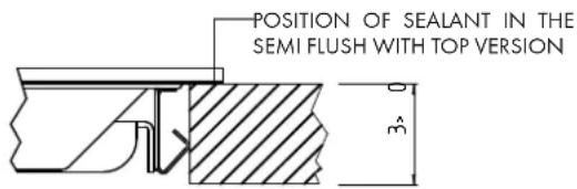
text_image
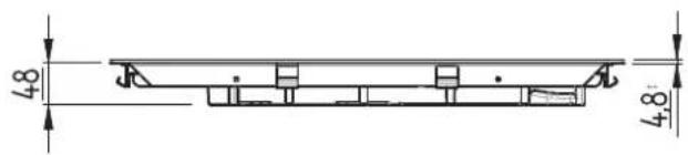
POSITION OF SEALANT IN THE SEMI FLUSH WITH TOP VERSION 3× 0°Fig. 7 - FSH 604 ID TS
text_image
4.8 4.8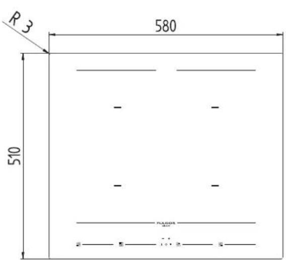
text_image
R₃ 580 510 FABOIS - + - 1.0 · 2.0 · 2.0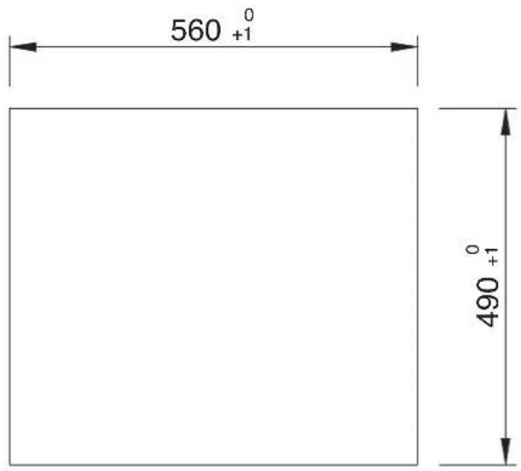
text_image
560° +1 490° +1Fig. 7 - FSH 402 ID TS
text_image
R₃ 400 52046 4,8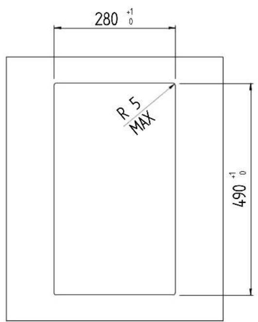
text_image
280 +1 0 R 5 MAX 490 +1 0Fig. 8 - FSH 604 ID TS Fig. 8 - FSH 402 ID TS
text_image
400V 2N~ N L2 L1 5 4 3 2 1 230V~ N L 5 4 3 2 1
text_image
~230V LNCher Client,
flowchart
graph TD
    A["A"] --> B["B"]
    B --> C["C"]
    C --> D["D"]
    D --> A
    style A fill:#fff,stroke:#000
    style B fill:#fff,stroke:#000
    style C fill:#fff,stroke:#000
    style D fill:#fff,stroke:#000
    note right of A "FULGOR"
    note left of A "-
+"
    note right of C "-
I 0 II - +"

text_image
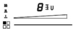
θ≡n θ≡u θ≡n θ≡uA: ZONE DE CUISSON A INDUCTION 220x180 2100/3700 W
B: ZONE DE CUISSON A INDUCTION 220x180 2100/3700 W
C: ZONE DE CUISSON A INDUCTION 220x180 2100/3700 W
D: ZONE DE CUISSON A INDUCTION 220x180 2100/3700 W
Fig. 2 - FSH 402 ID TS
natural_image
Simple line drawing of a brush applying paint to a surface, with no text or symbols present.text_image
280 +1 0 R 5 MAX 467 +1 0Fig. 8 - FSH 604 ID TS Fig. 8 - FSH 402 ID TS

text_image
400V 2N~ N L2 L1 5 4 3 2 1 230V~ N L 5 4 3 2 1
text_image
~230V LNflowchart
graph TD
    A["A"] --> B["B"]
    B --> C["C"]
    C --> D["D"]
    D --> A
    style A fill:#fff,stroke:#000
    style B fill:#fff,stroke:#000
    style C fill:#fff,stroke:#000
    style D fill:#fff,stroke:#000
    note right of A "FULCOR"
    note left of A "-
+"
    note right of C "-
I 0 II"

text_image
8 3 u 8 3 u 8.88 - 3 + i 0 11 8.3 u 8.3 uA: INDUKTIONS-KOCHFELD 220x180 2100/3700 W
B: INDUKTIONS-KOCHFELD 220x180 2100/3700 W
C: INDUKTIONS-KOCHFELD 220x180 2100/3700 W
D: INDUKTIONS-KOCHFELD 220x180 2100/3700 W
Abb. 2 - FSH 402 ID TS

natural_image
Simple line drawing of a hand holding a tool with a curved handle and droplets, no text or symbols present.text_image
280 +1 0 R 5 MAX 467 +1 0Abb. 8 - FSH 604 ID TS Abb. 8 - FSH 402 ID TS

text_image
400V 2N~ N L2 L1 5 4 3 2 1 230V~ N L 5 4 3 2 1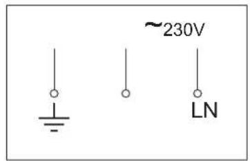
text_image
~230V LNEstimado cliente,
flowchart
graph TD
    A["A"] --> B["B"]
    B --> C["C"]
    C --> D["D"]
    D --> A
    style A fill:#fff,stroke:#000
    style B fill:#fff,stroke:#000
    style C fill:#fff,stroke:#000
    style D fill:#fff,stroke:#000
    note right of A "FULCOR"
    note left of A "-
+ 1 0 1"
text_image
8 3 u 8 3 u 8.88 - 3 + i 0 11 8.3 u 8.3 unatural_image
Simple line drawing of a hand holding a tool with a curved handle and droplets, no text or symbols present.text_image
280 +1 0 R 5 MAX 490 +1 0 0.4Fig. 8 - FSH 604 ID TS Fig. 8 - FSH 402 ID TS

text_image
400V 2N~ N L2 L1 5 4 3 2 1 230V~ N L 5 4 3 2 1
text_image
~230V LNPrezado Cliente,
flowchart
graph TD
    A["A"] --> B["B"]
    B --> C["C"]
    C --> D["D"]
    D --> A
    style A fill:#fff,stroke:#000
    style B fill:#fff,stroke:#000
    style C fill:#fff,stroke:#000
    style D fill:#fff,stroke:#000
    note right of A "FULGOR"
    note left of A "-
+ 1 0 1"

text_image
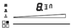
θ≡n θ≡u θ≡n θ≡uA: ZONA DE COZEDURA POR INDUÇÃO 220x180 2100/3700 W
B: ZONA DE COZEDURA POR INDUÇÃO 220x180 2100/3700 W
C: ZONA DE COZEDURA POR INDUÇÃO220x180 2100/3700 W
D: ZONA DE COZEDURA POR INDUÇÃO 220x180 2100/3700 W
Fig. 2 - FSH 402 ID TS

natural_image
Simple line drawing of a hand using a paintbrush to clean or brush residue (no text or symbols)text_image
280 +1 0 R 5 MAX 490 +1 0Fig. 8 - FSH 604 ID TS Fig. 8 - FSH 402 ID TS

text_image
400V 2N~ N L2 L1 5 4 3 2 1 230V~ N L 5 4 3 2 1
text_image
~230V LNFULGOR
MILANO
SINCE 1949