Solar Panel 400W - Solar panel ECOFLOW - Free user manual and instructions
Find the device manual for free Solar Panel 400W ECOFLOW in PDF.
| Product Type | Photovoltaic Solar Panel |
| Brand | EcoFlow |
| Model | Solar Panel 400W |
| Nominal Power | 400 W (±3%) |
| Open Circuit Voltage | 37,10 V (±3%) |
| Short Circuit Current | 13,79 A (±5%) |
| Maximum Operating Voltage | 31,00 V |
| Maximum Operating Current | 12,90 A |
| Maximum System Voltage | 1500 V DC (UL) |
| Maximum Fuse Current | 25 A |
| Net Weight | Approximately 21.8 kg (48.1 lb) |
| Dimensions (L×W×H) | 1722 × 1134 × 35 mm |
| Protection Rating | IP68 |
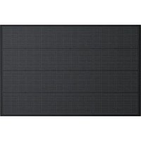
| Cell Type | Monocrystalline Silicon |
| Operating Temperature | -20 to 50 °C |
| Storage Temperature | -20 to 50 °C |
| Max Relative Humidity | < 85% RH |
| Frame Material | Anodized Aluminum |
| Surface Material | Tempered Glass |
| Cable Cross Section | 4 mm² |
| Number of Mounting Holes | 12 (14 × 9 mm) |
| Package Contents | Solar panel, user manual, warranty card |
| Warranty | See included warranty card |
Frequently Asked Questions - Solar Panel 400W ECOFLOW
User questions about Solar Panel 400W ECOFLOW
0 question about this device. Answer the ones you know or ask your own.
Ask a new question about this device
Download the instructions for your Solar panel in PDF format for free! Find your manual Solar Panel 400W - ECOFLOW and take your electronic device back in hand. On this page are published all the documents necessary for the use of your device. Solar Panel 400W by ECOFLOW.
USER MANUAL Solar Panel 400W ECOFLOW
text_image
Blank grid paper with dashed and solid lines, likely for text entry or layout reference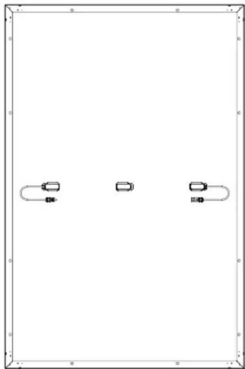
natural_image
Pure diagram of three rectangular objects with rounded ends, no text or symbols presentDisclaimer
Please read this User Manual and ensure you understand it fully before using the product. Please keep this User Manual properly for future reference. Any incorrect usage may result in severe injury to the user or others, damage to the product, or loss of property. By using this product, the user will be deemed as having understood, recognized, and accepted all the terms and contents of the User Manual, and will be responsible for any incorrect usage and all consequences arising therefrom. EcoFlow hereby disclaims any liability for any losses due to the user's failure to use the product in accordance with the User Manual.
In compliance with laws and regulations, EcoFlow shall have the final right to interpret this document and all related documents for this product. Any update, revision, or termination of the contents thereof, if necessary, shall be made without prior notice, and users may visit the official website of EcoFlow for the latest information on the product.
Contents
Technical Specifications 1
Safety Instructions 2
Installation 2
Usage 2
Pre-installation Requirements 3
How to Connect Multiple Solar Panels 3
How to Use Mounting Hole 4
How to Choose the Installation Environment 4
Installation Steps 5
Precautions 5
Triangle Bracket Installation 5
Support Bracket Installation 6
Bolt Installation 6
Pressing Block Installation 7
Care and Maintenance 7
Common Faults and Handling 8
What's in the Box 8
FAQ 8
Technical Specifications
General Information
| Rated Power | 400W (±3%) |
| Open Circuit Voltage | 37.10V (±3%) |
| Short Circuit Current | 13.79A (±5%) |
| Maximum Operating Voltage | 31.00V |
| Maximum Operating Current | 12.90A |
| Temperature Coefficient of Rated Power | -0.38%/°C |
| Temperature Coefficient of Open Circuit Voltage | -0.35%/°C |
| Temperature Coefficient of Short Circuit Current | 0.06%/°C |
| Maximum System Voltage | 1500V DC (UL) |
| Maximum Fuse Current | 25A |
Specifications
| Net weight | Approx. 21.8kg(48.1 lbs) |
| Dimensions | 1722*1134*35mm(67.8*44.6*1.38in) |
Testing and Certification


IP68
* Standard Test Conditions: 1000 W/m², AM1.5, 25°C (77°F)
Safety Instructions

Installation
- This solar system is to be installed by a qualified solar installation company.
- Do not disassemble the module or nameplate by yourself, otherwise this may void the warranty.
- Please make sure to use the installation components (including connectors, connecting cables, and brackets) provided by us. Before installation, the solar panel should be completely covered with opaque material and the positive and negative terminals disconnected to prevent power generation.
- Please carefully check whether the solar panel has broken glass or a damaged back panel. If it does, please stop installing or using it immediately.
- When installing, do not wear any jewelry made of metal, and only use insulated tools approved for electrical installation.
- When multiple solar panels are installed in series or parallel, the cross-sectional area of the cable and the capacity of the connector must be appropriate to the maximum short circuit current of the system.
- Do not install modules near open flames or inflammables and explosives. Do not install solar system in places with water immersion, watering devices, or sprinklers.
- Do not let children approach the installation site or touch any electrical modules.
- Do not step on the solar panel or any parts.
- Do not touch the solar panel (especially the back panel) with sharp tools.
- You must comply with local and national regulations during roof and ground installations
Usage
- The module overcurrent protection rating applies to DC fuses.
- Do not plug or unplug any system connectors while the circuit is under load.
- Make sure the fire resistance rating of the system is up to standard, comply with local electrical safety regulations, and configure module accessories (such as fuses, circuit breakers, grounding connectors, etc.) as needed.
- Please make sure that the installation area of the solar panel system is well ventilated and the connectors are clean and dry.
- All solar system connections must be sealed to prevent moisture.
- When installing and using solar system, be sure to follow the safety regulations for all other modules in the system, including connecting wires and cables, connectors, controllers, charging regulators, inverters, accumulators, and other rechargeable batteries.
- Do not apply any substance that may block light (such as paint, adhesive, etc.) on the light-receiving surface of the solar panel.
- Do not directly irradiate the surface of the module with artificially amplified sunlight.
- Do not put heavy objects on the solar panel during use, to avoid damage to the panel.
Pre-installation Requirements
How to Connect Multiple Solar Panels
You can connect multiple solar panels in series or parallel, but the series connection method is recommended. Please purchase the extension cable, parallel cable, and other accessories required for the connection by yourself. It should also be noted that all connections in a solar panel system should be made using solar panels with the same specifications. Connection method:
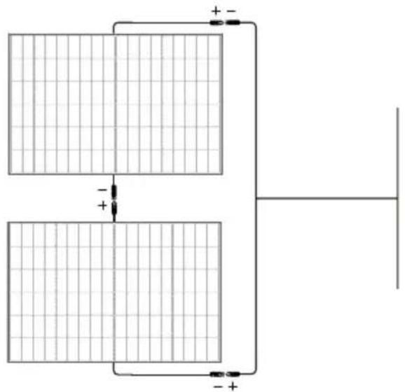
1. Series Connection
Series connection can increase the voltage. When connecting in series, connect the positive pole of one module to the negative pole of the second module.
natural_image
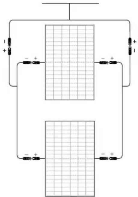
Pure electrical circuit lines without any symbols2. Parallel Connection
Parallel connection can increase the current value. For parallel connection, please connect the positive and negative cables of one module and the second module correspondingly.
text_image
Circuit diagram showing two rectangular blocks with labeled terminals and polarity indicatorsHow to Use Mounting Hole
When installing the bracket, be sure to use the mounting holes reserved for the solar panel. Do not modify the module frame without permission, otherwise this may void the warranty. Specific location as shown below:
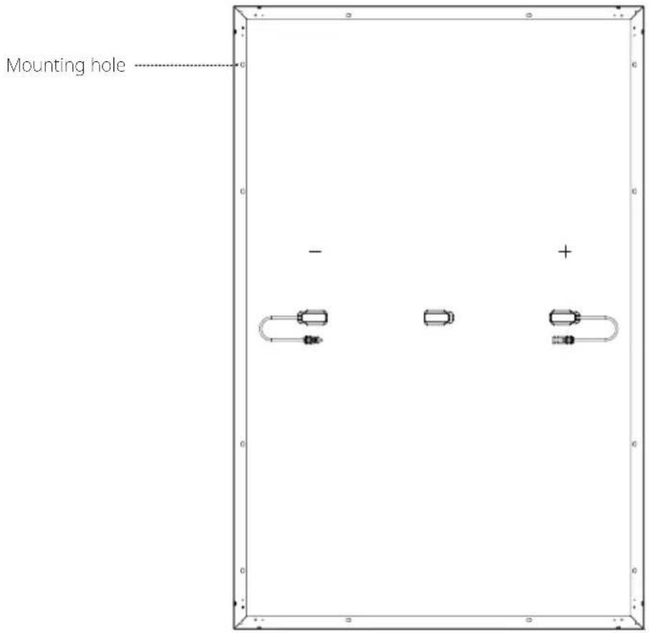
text_image
Mounting hole - +Number: 12; size: 14*9mm(0.55*0.35in)
How to Choose the Installation Environment
In order to ensure the normal operation of the solar panel, please choose the suitable installation environment according to the following table:
No. Environmental conditions Range
1 Recommended operating temperature -20 to 50°C (-4 to 122°F)
2 Operating temperature limits -40 to 85°C (-40 to 185°F)
3 Storage temperature -20 to 50°C (-4 to 122°F)
4 Temperature <85RH%
* The operating environment temperature refers to the monthly average maximum and minimum temperature of the installation site.
- If you plan to use the module in a place with high humidity (>85RH%), please consult the EcoFlow technical support team for a suitable installation method first.
- Install the solar panel in an area that will not be shaded throughout the year. Even small amounts of shade should be avoided (e.g. overhead lines, dirt, snow).
- For more solar system installation guidelines, please refer to your local solar system installation guide or the solar manufacturer's installation requirements.
Installation Steps
Precautions
- The installation methods listed in this manual are for reference only. Please purchase the required installation kit yourself. For specific installation steps, please refer to the manual of the corresponding kit.
- The installation tilt angle of the solar panel should be kept above 10^ , otherwise dust accumulation and damage to the performance of the module is likely. If the tilt angle is too small, please increase the frequency of cleaning the solar panel.
- During solar system installation, it is recommended to install solar panel with similar appearance and color together.
- The gap between two adjacent solar panels should not be less than 20mm. The minimum distance between the frame of a single solar panel and the installation plane should be 40mm.
- The maximum design load of the solar panel, as well as excessive forces due to thermal expansion of the support structure, must be considered during system design. The specific system installation design is the responsibility of the installation company.
Tilt Mount Bracket Installation
The system can flexibly regulate the elevation angle via adjusting the bracket to keep the solar panel at a vertical angle to the sunlight. It can also be fixed on a flat level for a long time. It is recommended that you place the modules horizontally during use to ensure the stability of the system.
Please use the tilt mount bracket kit for the installation. The kit includes the fixing bracket, adjusting bracket, and attached bolts. If needed, please visit EcoFlow's official sales channel for the relevant purchase information.
How to Install
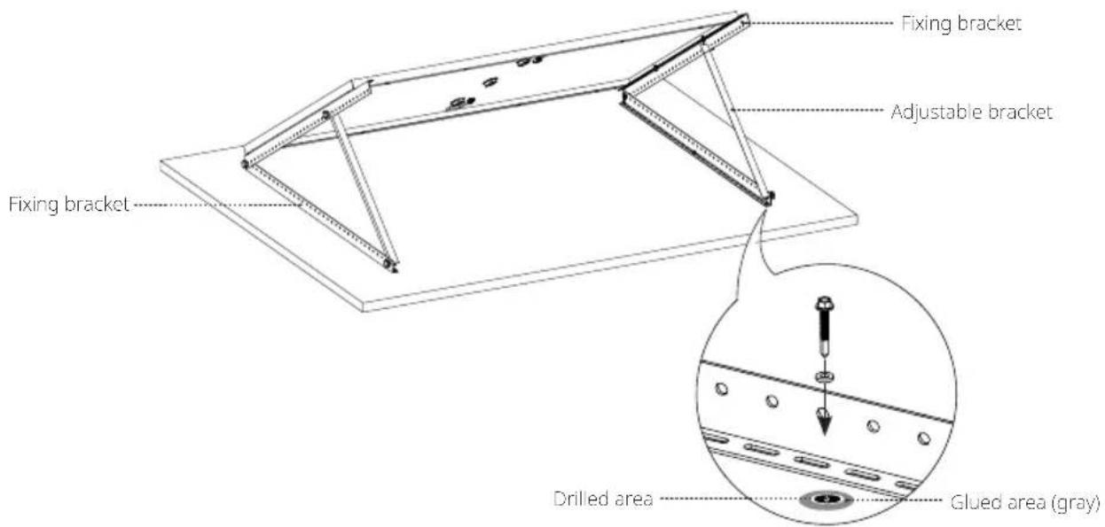
text_image
Fixing bracket Adjustable bracket Fixing bracket Drilled area Glued area (gray)Package List
natural_image
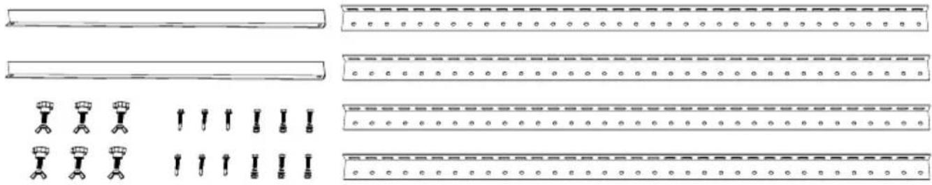
Pure technical line drawings of mechanical components without any text, numbers, or symbolsSupport Bracket Installation
The solar panels in this system can be fixed parallel to the installation surface using the support brackets. Each module requires the installation of at least eight support brackets to ensure the stability of the system.
Please use the support bracket kit to connect the solar panel, and fix the solar panel to the pre-installation surface with the drill screws. If needed, please visit EcoFlow's official sales channel for the relevant purchase information on the kit.
How to Install
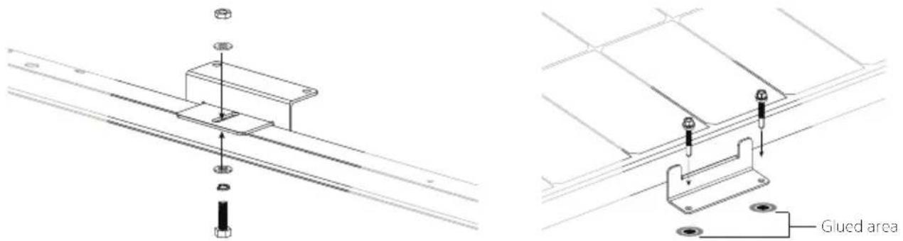
text_image
Technical diagram showing assembly of a mounted component with labeled 'Glued area' and mechanical partsFix the support bracket and the solar panel. Use the mounting hole to fix the solar panel in the pre-installation position
Package List
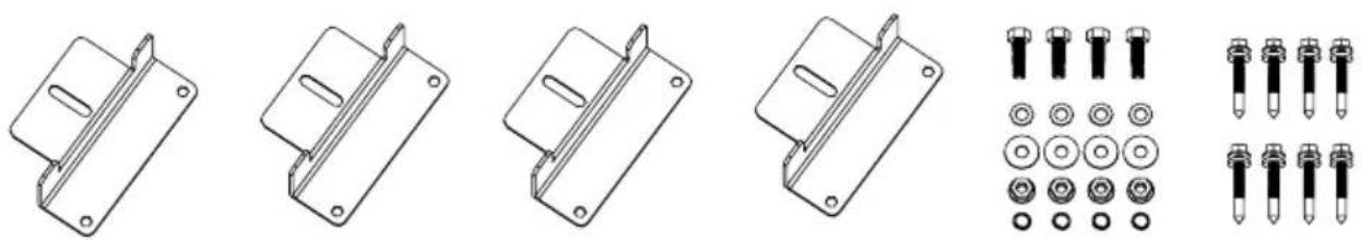
natural_image
Technical line drawings of mechanical components including brackets, bolts, and screws (no text or symbols)*A 400W solar panel needs at least 2 sets of support brackets
Bolt Installation
The solar panels in this system can be fixed on the bracket with a bolt kit. It is recommended that you place the module vertically when using the bolts to ensure the stability of the system.
Please use the bolt kit to fix the solar panel on the bracket system. The applied torques are 16–20 N·m for M8 and 14–18 N·m for M6. You need to purchase the bolt kit yourself. Please select anti-corrosion stainless steel fastening materials.
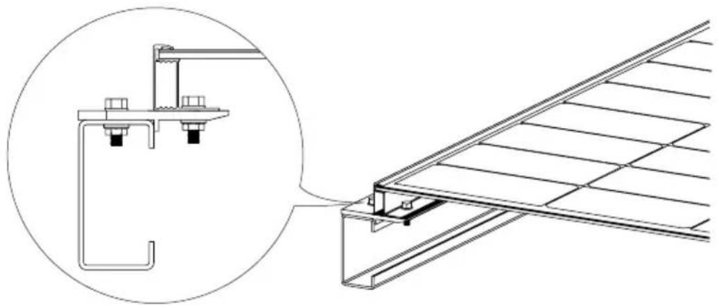
natural_image
Technical line drawing of a structural assembly with an inset showing a detail view of a bracket and panel (no text or symbols present)Pressing Block Installation
In this system, pressing blocks can be used to fix single solar panels or connect multiple solar panels. It is recommended that you place the panels vertically during use to ensure the stability of the system.
Please use a certain number of pressing blocks and M8 bolts to fix the module on the bracket. Each module must be fixed with at least four pressing blocks. The applied torque is 16–20 N·m. You need to purchase the pressing blocks and the bolt kit yourself. Please make sure the length of the pressing blocks is over 50mm, and the thickness is over 3mm.
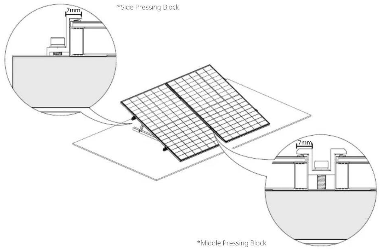
text_image
*Side Pressing Block *Middle Pressing Block- Considering the actual situation of local wind load and snow load, you may need to use other means to ensure the stability of the system, such as increasing the number of pressing blocks, strengthening the mounting holes, or increasing the length of the pressing blocks.
- Do not allow deformation of the aluminum frame caused by the pressure of the pressing block. At the same time, do not use pressing blocks that are too thick and cast shadows over the module.
- It is necessary to ensure that the pressing block is in contact with the surface of the solar panel for more than 7mm, and to avoid blocking the front of the solar panel.
Care and Maintenance
The following maintenance is recommended to maintain optimal performance of the module:
- When there is dust accumulation on the glass surface of the solar panel, please clean it with a soft sponge or damp cloth. To remove stubborn dirt, you can wipe it with a mild detergent. It is recommended to clean in the morning and evening when sunlight is weak (irradiance ≤slant 200W / m^2 ).
- Prevent the accumulation of leaves and other debris on the surface of solar panels. Otherwise, this will not only affect the efficiency of power generation but also cause excessive local current and burn solar components.
- Check electrical and mechanical connections at least every six months to confirm that they are clean, secure, and undamaged.
Common Faults and Handling
- Before commissioning, please test the serial modules of the system.
- When testing module performance outdoors, do not connect the system to the load and pay attention to personal safety.
- Should abnormal power generation occur, troubleshoot the issue by following the steps below:
① Check all wiring to ensure that there are no open circuits or poor connections;
② Check the open circuit voltage of each module;
③ First cover the module with opaque material to check the open circuit voltage. Then remove the opaque material, measure the open circuit voltage at its terminals, and compare the data from both points.
- If the voltage between the terminals differs by over 5% from the nominal value at an irradiance of ≥slant 700W / m^2 , this indicates a poor electrical connection.

All commissioning and repair work on this solar system must be performed by a qualified solar technician. Maintenance instructions for all components used in the system (such as brackets, charging regulators, inverters, batteries, etc.) must be followed.
What's in the Box
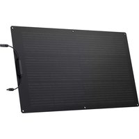
Solar Panel (Front) Solar Panel (Rear)
natural_image
Blank grid paper with dashed line at center (no text or symbols)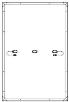
natural_image
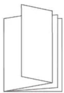
Pure diagram of three horizontal lines with rounded ends and small circular symbols inside, no text or labels present.User Manual and Warranty Card
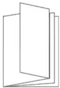
natural_image
Abstract geometric diagram of stacked rectangular panels (no text or symbols)
This solar panel module is supplied with a three-part junction box and 4mm^2 wires. If you need more of these components, please visit EcoFlow's official sales channel for the relevant purchase information.
FAQ
Why can't the solar panel reach the nominal power in actual use?
It is normal that the actual power does not reach the nominal power. You can get close to the nominal power by correcting for the following factors:
1. Light Intensity
Changes in the intensity of sunlight will cause the output power to fluctuate up and down. The actual power will be closer to the nominal power when used at noon on a sunny day, and will be less than the nominal value in the early morning or afternoon. Weather conditions will also affect the amount of sunlight that shines on the panel. For example, you are much less likely to achieve the nominal power in hazy, cloudy, or rainy conditions.
2. Surface Temperature
The surface temperature of the solar panel affects the power performance of the solar panel. The lower the surface temperature, the better the power performance. For example, when using solar panels in winter, the power is usually higher than in summer. Solar panels generally reach temperatures close to 60^ C ( 140^ F) during summer. This reduces nominal power by 10–15%, despite the higher levels of light shining on the panel.
3. Light Angle
When the solar panel and the light angle are perpendicular, better power performance can be obtained. However, under special installation conditions (such as the roof of an RV), the solar panel can only be used in a tiled manner, which makes it impossible to form a vertical angle with the sunlight, resulting in a power loss of about 5–15%.
4. Light Occlusion
When using solar panels, try to ensure that the surface is not covered, including projection, foreign objects, glass, etc., which will cause a significant drop in power.
If all of the above conditions are met, but the power used is much smaller than the nominal value, it may be a fault situation. In this case, you can contact EcoFlow customer service for assistance.
What is the power range that a 400W solar panel can typically achieve?
On a sunny day without clouds and direct sunlight, the power range of a 400W solar panel is between 320–350W (this data is obtained under the conditions of irradiance of 800–900W/m ^-2 and the panel surface at 50°C (122°F)). The nominal data of the solar panel is obtained by testing under the conditions of AM1.5, meteorological conditions of 1000W/m ^7 , and panel surface temperature of 25°C (77°F). A power close to the nominal value can usually be reached at midday on a sunny day in winter.
What is the operating temperature range of the solar panels?
Please refer to the content in How to Choose the Installation Environment in this manual.
What are the precautions for the use of solar panels?
The solar panel is made of monocrystalline silicon wafer. During installation and use, please do not drop it on the ground with force, or use tools to hit the surface. Do not step on or sit on the solar panel, so as not to cause the monocrystalline silicon wafer to break and affect its use. Artificial damages will void the warranty.
Can I use solar panels of different specifications for mixed use?
Yes, but it is not recommended. Different energy storage controllers have requirements and restrictions on the output of solar panels. When solar panels with different current values are used in series, they will be limited, resulting in the inability to release the output power and even the short-board effect of 1+1<2 .
Can I connect solar panels in parallel?
Yes. Parallel connection can double the current and increase the power. You can refer to the requirements for solar controllers and energy storage devices to ensure that they support larger values of input current to better determine the number of parallel connected solar panels. Additionally, it is necessary to pay attention to select a wire with a suitable wire diameter for safe connection according to the change of the output current.
Do solar panels need to be cleaned frequently?
Yes. When used outdoors for a long time, solar panels are prone to accumulate dust and foreign objects on the surface, causing a certain degree of light occlusion and reducing the output of power generation. Frequent cleaning keeps the surface of the solar panel clean and free of obstructions, allowing for better solar panel power output.
ECOFLOW
400 W Rigid Solar Panel
text_image
Blank grid paper with dashed and solid lines, likely for text entry or paper layout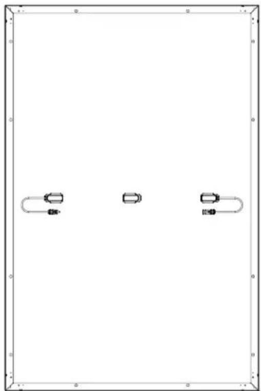
natural_image
Pure diagram of three rectangular shapes with rounded corners and horizontal lines, no text or symbols present.Haftungsausschluss
natural_image
Pure electrical circuit lines without any symbolstext_image
Circuit diagram showing two rectangular blocks with grid patterns and connected resistors labeled with polarity signs.natural_image
Pure technical line drawings of mechanical components without any text, numbers, or symbolsnatural_image
Technical line drawings of mechanical components including brackets, bolts, and screws (no text or symbols)natural_image
Technical line drawing of a structural assembly with an inset showing a bracket and mounting detail (no text or symbols)Installation des Pressblocks
natural_image
Blank grid paper with no text, numbers, or symbols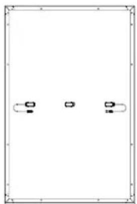
natural_image
Pure diagram of three vertical slots with curved arrows, no text or symbols presentGarantiekarte
natural_image
Abstract geometric diagram of stacked rectangular planes (no text or symbols)
text_image
Blank grid paper with dashed and solid lines, likely for text entry or layout reference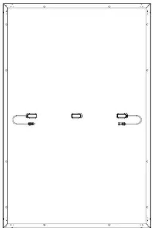
natural_image
Pure diagram of three rectangular objects with rounded ends, no text or symbols presentnatural_image
Pure electrical circuit lines without any symbolstext_image
Circuit diagram showing two rectangular blocks with grid patterns and connected resistors labeled with polarity indicators.natural_image
Pure electrical circuit lines without any symbolsnatural_image
Technical line drawings of mechanical components including brackets, plates, and bolts (no text or symbols)natural_image
Technical line drawing of a structural assembly with an inset showing a bracket and mounting bracket (no text or symbols)natural_image
Blank grid paper with no text, numbers, or symbols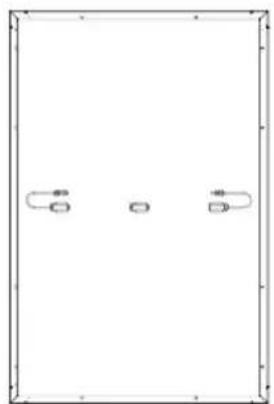
natural_image
Simple line drawing of a rectangular frame with three small rounded rectangles on each side (no text or symbols)
natural_image
Abstract geometric diagram of three overlapping rectangular panels (no text or symbols)
text_image
Blank grid paper with faint dashed and solid lines, likely for text entry or paper layout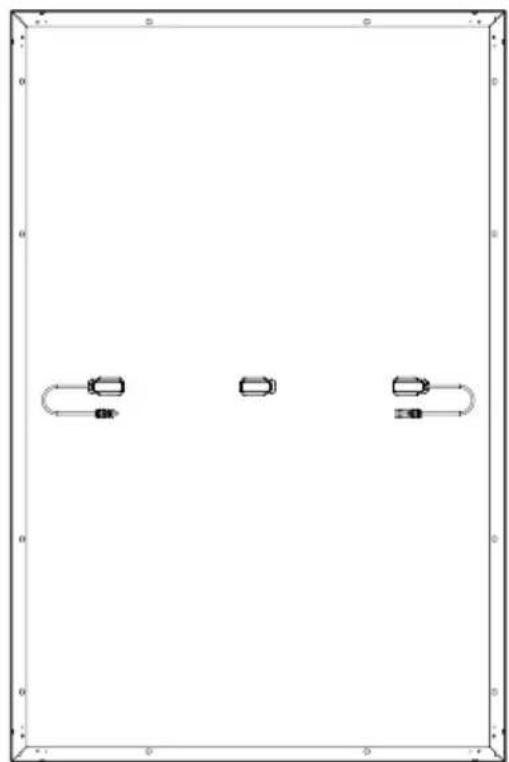
natural_image
Pure diagram of three rectangular objects with rounded corners and horizontal lines, no text or symbols present.natural_image
Pure electrical circuit lines without any symbolstext_image
Electrical circuit diagram showing two parallel plates with labeled terminals and polarity indicatorsnatural_image
Pure technical line drawings of mechanical components without any text, numbers, or symbolsnatural_image
Technical line drawings of mechanical components including brackets, plates, and bolts (no text or symbols)natural_image
Technical line drawing of a structural assembly with an inset showing a detail view of a bracket and a close-up of the component (no text or symbols present)natural_image
Blank grid paper with no text, numbers, or symbols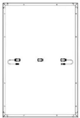
natural_image
Pure diagram of a rectangular frame with three small rectangular symbols on the sides, no text or labels present.garanzia
natural_image
Abstract geometric diagram of stacked rectangular panels (no text or symbols)
text_image
Blank grid paper with faint dashed and solid lines, likely for digital entry or paper layout reference.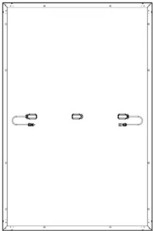
natural_image
Pure diagram of three rectangular shapes with no text, numbers, or symbolsnatural_image
Pure electrical circuit lines without any symbolstext_image
Circuit diagram showing two rectangular blocks with grid patterns and connected resistors labeled with polarity indicators.natural_image
Pure electrical circuit lines without any symbolsnatural_image
Technical line drawings of mechanical components including brackets, bolts, and screws (no text or symbols)natural_image
Technical line drawing of a structural assembly with an inset showing a bracket detail (no text or symbols)natural_image
Blank grid paper with no text, numbers, or symbols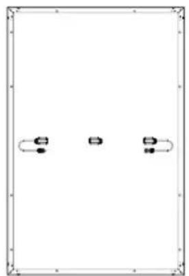
natural_image
Pure diagram of a rectangular frame with four small rectangular elements and curved lines, no text or symbols present.
natural_image
Abstract geometric line drawing of stacked rectangular panels (no text or symbols)
text_image
Blank grid paper with faint dashed lines, likely for text entry or layout reference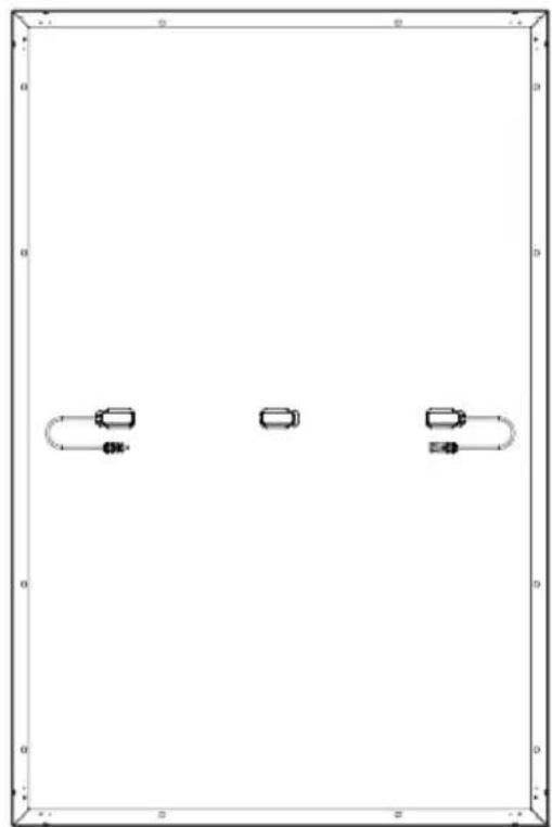
natural_image
Pure diagram of three rectangular objects with curved and straight lines inside, no text or symbols presentDisclaimer
natural_image
Pure electrical circuit lines without any symbolstext_image
Circuit diagram showing two rectangular blocks with labeled terminals and polarity indicatorsnatural_image
Pure technical line drawings of mechanical components without any text, numbers, or symbolsSteunbeugel installeren
text_image
Technical diagram showing two mechanical assembly configurations with labeled components and a reference line 'Lijmgebied'natural_image
Technical line drawings of mechanical components including brackets, bolts, and screws (no text or symbols)natural_image
Technical line drawing of a structural assembly with an inset showing a bracket and mounting detail (no text or symbols)Drukblokken installeren
natural_image
Blank grid paper with no text, numbers, or symbols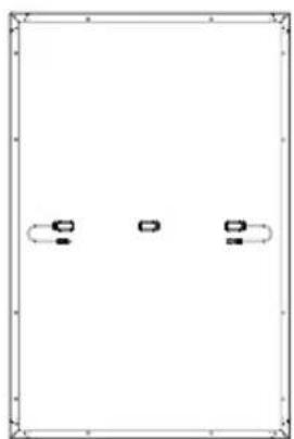
natural_image
Pure diagram of three identical rectangular shapes with curved and straight lines inside, no text or symbols present.garantiekaart
natural_image
Abstract geometric diagram of stacked rectangular panels (no text or symbols)Veelgestelde vragen
text_image
Blank grid paper with dashed and solid lines, likely for paper layout or paper scheduling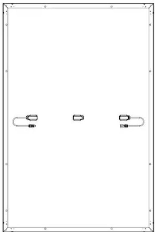
natural_image
Pure diagram of three rectangular shapes with no text, numbers, or symbolsnatural_image
Pure electrical circuit lines without any symbolstext_image
Electrical circuit diagram showing two parallel plates with labeled current directions and polarity indicatorsnatural_image
Pure technical line drawings of mechanical components without any text, numbers, or symbolsnatural_image
Technical line drawings of mechanical components including brackets, plates, and bolts (no text or symbols)natural_image
Technical line drawing of a structural assembly with an inset showing a bracket detail (no text or symbols)natural_image
Blank grid paper with no text, numbers, or symbols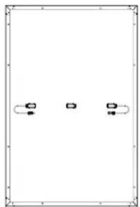
natural_image
Pure diagram of three identical rectangular shapes with curved lines on each, no text or symbols present.
natural_image
Abstract line drawing of stacked rectangular sheets (no text or symbols)