HCF91531X - Basket BEKO - Free user manual and instructions
Find the device manual for free HCF91531X BEKO in PDF.
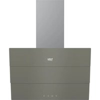
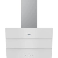
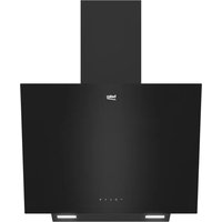
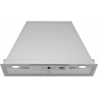
| Product type | Extractor or recirculating hood |
| Brand | Beko |
| Model | HCF91531X |
| Dimensions (W x D x H) | 90 cm x 50 cm x 60 cm (estimated) |
| Weight | Approximately 15 kg |
| Power supply | 220-240 V ~ 50 Hz |
| Maximum power | 200 W (estimated) |
| Noise level | 55-65 dB(A) (estimated) |
| Maximum air flow | 600 m³/h (estimated) |
| Number of speeds | 3 + intensive speed |
| Control type | Mechanical or electronic depending on version |
| Lighting | 2 halogen or incandescent bulbs (max 40 W each) |
| Grease filter | Dishwasher-safe or hand wash every 2 months |
| Activated carbon filter | Replace every 4 months (non-reusable) or washable every 2 months (reusable) |
| Material | Stainless steel and glass |
| Minimum distance from hob | 65 cm |
| Insulation class | Class II |
| Operating modes | Extracting (external evacuation) or filtering (internal recirculation) |
| Air outlet diameter | 150 mm (estimated) |
| Additional functions | Automatic shut-off timer (15 min), Clean Air function, filter saturation indicator |
| Safety | Automatic shutdown in case of overheating, protection against flow reversals |
| Maintenance | Clean exterior with denatured alcohol or neutral detergent |
Frequently Asked Questions - HCF91531X BEKO
User questions about HCF91531X BEKO
0 question about this device. Answer the ones you know or ask your own.
Ask a new question about this device
Download the instructions for your Basket in PDF format for free! Find your manual HCF91531X - BEKO and take your electronic device back in hand. On this page are published all the documents necessary for the use of your device. HCF91531X by BEKO.
USER MANUAL HCF91531X BEKO
Please read this user manual first!
Dear Customer,
Thank you for preferring a Beko product. We hope that you get the best results from your product which has been manufactured with high quality and state-of-the-art technology. Therefore, please read this entire user manual and all other accompanying documents carefully before using the product and keep it as a reference for future use. If you handover the product to someone else, give the user manual as well. Follow all warnings and information in the user manual.
Remember that this user manual is also applicable for several other models. Differences between models will be identified in the manual.
Explanation of symbols
Throughout this user manual the following symbols are used:

Important information or useful hints about usage.

Warning for hazardous situations with regard to life and property.
Warning for electric shock.

This product was manufactured using the latest technology in environmentally friendly conditions.
text_image
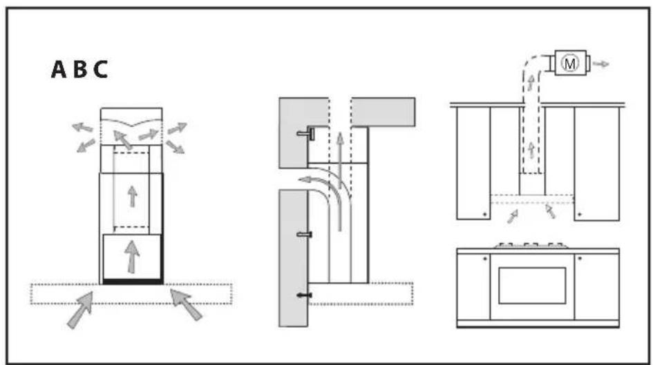
A B C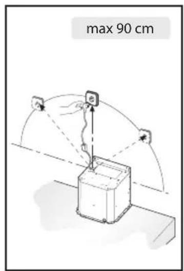
text_image
max 90 cmFig.1
text_image
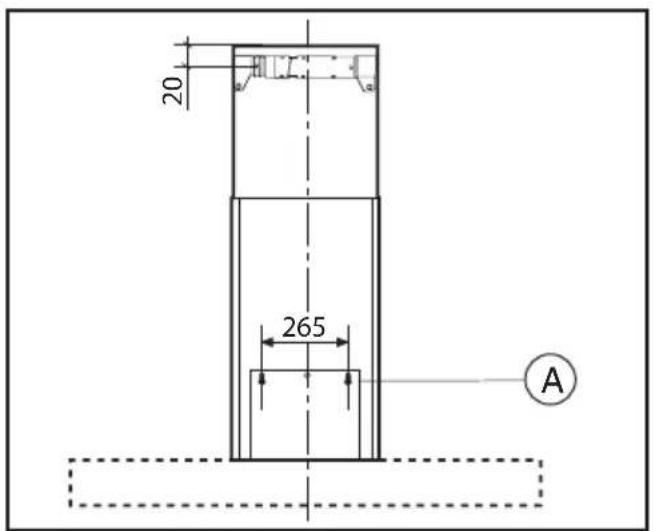
20 265 A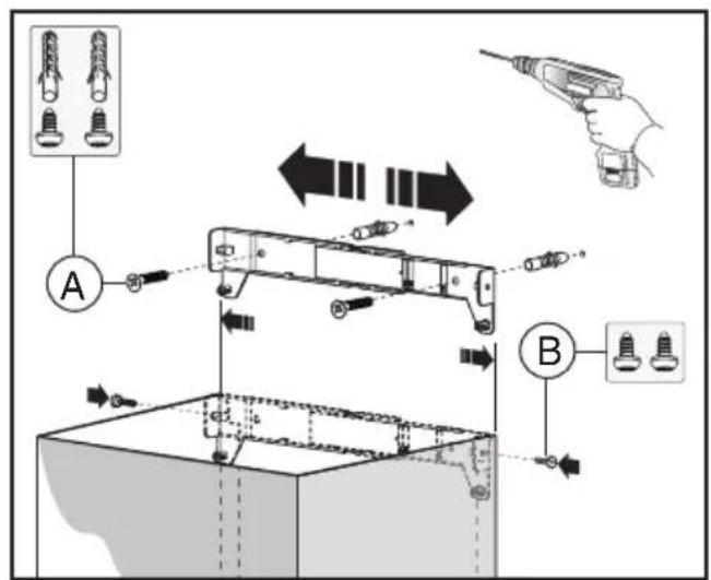
text_image
Diagram illustrating a mechanical assembly or mounting process with labeled components A and B, showing tool application and directional arrows.Fig.2 Fig.3
text_image
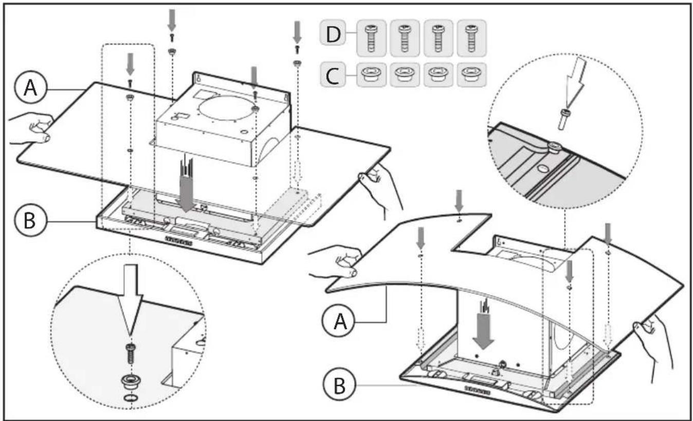
Technical diagram illustrating assembly steps of a mechanical device with labeled components A, B, C, D and their corresponding parts.Fig.4
text_image
1 2 90° A B CFig.5
text_image
Technical diagram showing a mechanical assembly with labeled parts B and C, including a tool and component assembly.Fig.6A
text_image
INCANDESCENT TUBOLAR LAMP Ø 25mm - L85- E14 - 40W CANDLE HALOGEN LAMP Ø 35mm - E14 - 28WFig.6B
text_image
Diagram illustrating hand positioning and movement of a device with labeled parts and directional arrowsFig.7
text_image
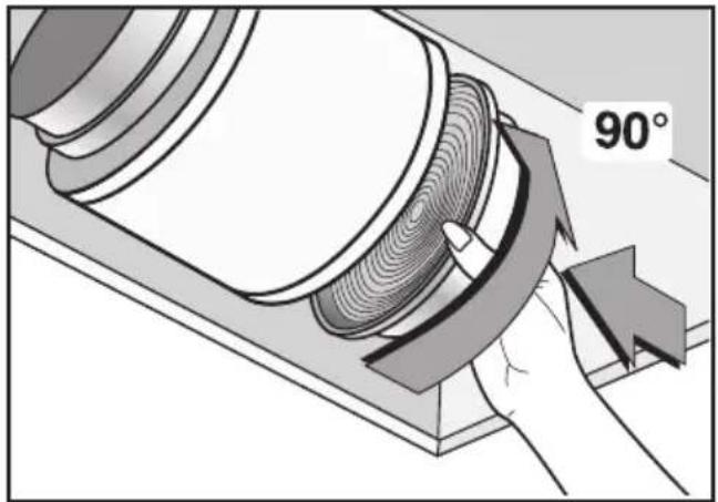
90°Fig.8
flowchart
graph TD
    A["0"] --> B["B"]
    B --> C["1"]
    D["1"] --> E["2"]
    E --> F["3"]
    G["1"] --> H["2"]
    H --> I["3"]
    J["1"] --> K["3"]
    K --> L["4"]
Fig.9
flowchart
graph TD
    A["Input Signal"] --> B["0"]
    B --> C["1"]
    C --> D["2"]
    D --> E["3"]
    E --> F["Output Signal"]
    subgraph Processing Block
        G["0123T"]
        H[" "]
        I[" "]
        J[" "]
    end
    G --> H
    H --> I
    I --> J
    J --> K["Output"]
    style G fill:#f9f,stroke:#333
    style H fill:#f9f,stroke:#333
    style I fill:#f9f,stroke:#333
    style J fill:#f9f,stroke:#333
    style K fill:#f9f,stroke:#333
Fig.10
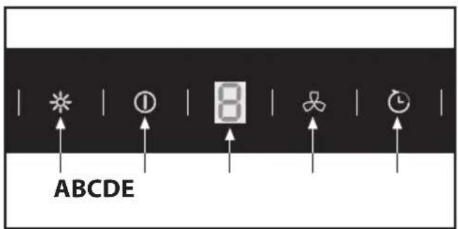
text_image
A B C D E OFF 8.Fig.11
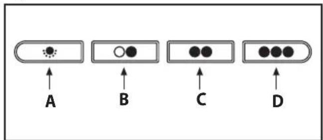
flowchart
graph TD
    A["Sun Icon"] --> B["Circle"]
    B --> C["●"]
    C --> D["●●●"]
Fig.12
text_image
ABCDEFig.13 Fig.14
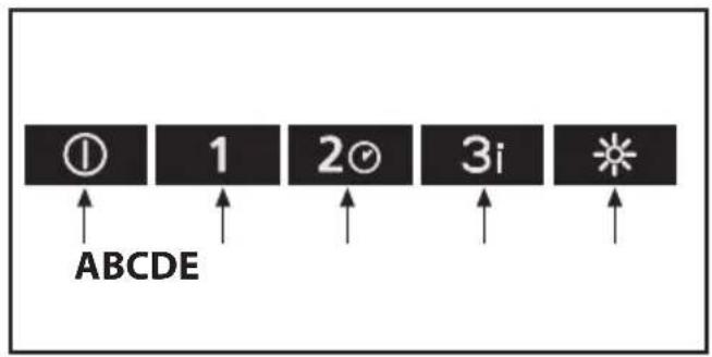
text_image
① 1 2○ 3i ABCDEITALIANO

GENERALITÀ
• Commandes (Fig.11):
- Commandes (Fig.14):
A = Touche ON/OFF
E = Touche ON/OFF LUMIÈRES
Carefully read the following important information regarding installation safety and maintenance. Keep this information booklet accessible for further consultations. The appliance has been designed for use in the ducting version (air exhaust to the outside – Fig.1B), filtering version (air circulation on the inside – Fig.1A) or with external motor (Fig.1C).
SAFETY PRECAUTION
- Take care when the cooker hood is operating simultaneously with an open fireplace or burner that depend on the air in the environment and are supplied by other than electrical energy, as the cooker hood removes the air from the environment which a burner or fireplace need for combustion. The negative pressure in the environment must not exceed 4Pa (4x10⁻⁵ bar). Provide adequate ventilation in the environment for a safe
operation of the cooker hood.
Follow the local laws applicable for external air evacuation.
Before connecting the model to the electricity network:
- Control the data plate (positioned inside the appliance) to ascertain that the voltage and power correspond to the network and the socket is suitable. If in doubt ask a qualified electrician.
- If the power supply cable is damaged, it must be replaced with another cable or a special assembly, which may be obtained direct from the manufacturer or from the Technical Assistance Centre.
- This device must be connected to the mains supply through either a plug fused 3A or hardwired to a 2 phase spur protected by 3A fuse.
2. Warning!
In certain circumstances electrical appliances may be a danger hazard.
A) Do not check the status of the filters while the cooker hood is operating.
B) Do not touch bulbs or adjacent areas, during or straight after prolonged use of the lighting installation.
C) Flambè cooking is prohibited underneath the cooker hood.
D) Avoid free flame, as it is damaging for the filters and a fire hazard.
E) Constantly check food frying to avoid that the overheated oil may become a fire hazard.
F) Disconnect the electrical plug prior to any maintenance.
G) This appliance is not intended for use by young children or infirm persons without supervision.
H) Young children should be supervised to ensure they do not play with the appliance
I) There shall be adequate ventilation of the room when the rangehood is used at the same time as appliances burning gas or other fuels.
L) There is a risk of fire if cleaning is not carried out in accordance with the instructions.
This appliance conforms to the European Directive EC/2002/96, Waste Electrical and Electronic Equipment (WEEE). By making sure that this appliance is disposed of in a suitable manner, the user is helping to prevent potential damage to the environment or to public health.

The symbol on the product or on the accompanying paperwork indicates that the appliance should not be treated as domestic waste, but should be delivered to a suitable electric and electronic appliance recycling collection point. Follow local guidelines when disposing of waste. For more information on the treatment, re-use and recycling of this product, please contact your local authority, domestic waste collection service or the shop where the appliance was purchased.
INSTALLATION INSTRUCTIONS
- Assembly and electrical connections must be carried out by specialised personnel.
- Wear protective gloves before proceeding with the installation.
• Electric Connection: - The appliance has been manufactured as a class II, therefore no earth cable is necessary. The plug must be easily accessible after the installation of the appliance. If the appliance is equipped with power cord without plug, a suitably
dimensioned omnipolar switch with 3 mm minimum opening between contacts must be fitted between the appliance and the electricity supply in compliance with the load and current regulations.
- The connection to the mains is carried out as follows:
BROWN = L line
BLUE = N neutral.
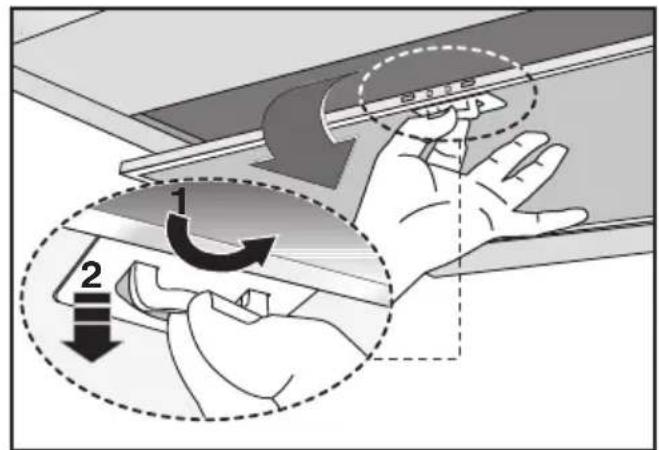
- The minimum distance between the support surfaces of the cooking pots on the cooker top and the lowest part of the cooker hood must be at least 65 cm. If a connection tube composed of two parts is used, the upper part must be placed outside the lower part. Do not connect the cooker hood exhaust to the same conductor used to circulate hot air or for evacuating fumes from other appliances generated by other than an electrical source. Before proceeding with the assembly operations, remove the anti-grease filter(s) (Fig.7) so that the unit is easier to handle.
- In the case of assembly of the appliance in the suction version prepare the hole for evacuation of the air.
- We recommend the use of an air exhaust tube which has the same diameter as the air exhaust outlet hole. If a pipe with a smaller diameter is used, the efficiency of the product may be reduced and its operation may become noisier.
Please note:
If your version of the appliance has decorative glass before installing the hood, carry out the following steps as shown in figure 4:
1 - Remove both the cooker hood body B and the glass panel A from the packaging and place them horizontally on a secure surface.
2 - Take the glass panel A and position it above the cooker hood body B.
3 - Fix the glass panel securely to the cooker hood body using the 4 sleeves C and 4 screws D as indicated.
- Fixing to the wall
Drill the holes A respecting the distances indicated (Fig.2). Fix the appliance to the wall and align it in horizontal position to the wall units. When the appliance has been adjusted, definitely fix the hood using the screws A (Fig.5). For the various installations use screws and screw anchors suited to the type of wall (e.g. reinforced concrete, plasterboard, etc.). If the screws and screw anchors are provided with the product, check that they are suitable for the type of wall on which the hood is to be fixed.
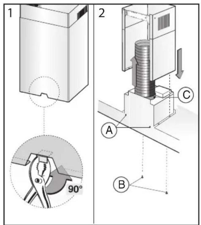
• Fixing the decorative telescopic flue
Warning! Caution! If your appliance model features the lower connector with a tab, before fixing it in place bend the tab inwards using a pair of pliers, as illustrated in figure 5, step1. Arrange the electrical power supply within the dimensions of the decorative flue. If your appliance is to be installed in the ducting version or in the version with external motor, prepare the air exhaust opening. Adjust the width of the support bracket of the upper flue (Fig.3). Then fix it to the ceiling using the screws A (Fig.3) in such a way that it is in line with your hood and respecting the distance from the ceiling indicated in Fig.2. Connect the flange C to the air exhaust hole using a connection pipe (Fig.5 - Stage 2). Insert the upper flue into the lower flue. Fix the lower flue to the hood using the screws B provided (Fig.5 - Stage 2), extract the upper flue up to the bracket and fix it with the screws B (Fig.3). To transform the hood from a ducting version into a filtering version, ask your dealer for the charcoal filters and follow the installation instructions.
- Filtering version
Install the hood and the two flues as described in the paragraph for installation of the hood in ducting version. To assemble the filtering flue refer to the instructions contained in the kit. If the kit is not provided, order it from your dealer as accessory. The filters must be applied to the suction unit positioned inside the hood. They must be centred by turning them 90 degrees until the stop catch is tripped (Fig.8).
USE AND MAINTENANCE
- We recommend that the cooker hood is switched on before any food is cooked. We also recommend that the appliance is left running for 15 minutes after the food is cooked, in order to thoroughly eliminate all contaminated air.
The effective performance of the cooker hood depends on constant maintenance; the anti-grease filter and the active carbon filter both require special attention.
- The anti-grease filter is responsible retaining the grease particles suspended in the air, therefore it is subject to clogging with variable frequency according to the use of the appliance.
- To prevent the danger of possible fires, at least every 2 months one must wash the anti-grease filters by hand using non-abrasive neutral liquid detergents or in the dishwasher at low temperatures and on short cycles.
- After a few washes, colour alterations may occur. This does not give the right to claim their replacement.
- The active carbon filters are used to purify the air that is sent back into the room and its function s to mitigate the unpleasant odours produced by cooking.
- The non-regenerable active carbon filters must be replaced at least every 4 months. The saturation of the active charcoal depends on the more or less prolonged use of the appliance, on the type of kitchen and on the frequency with which anti-grease filter is cleaned.
- Regenerable active charcoal filters must be washed by hand, with non abrasive neutral detergents, or in the dishwasher at a maximum temperature of 65^ C (the washing cycle must be complete without dishware). Remove excess water without damaging the filter, remove the plastic parts, and let the mat dry in the oven for at least 15 minutes approximately at a maximum temperature of 100^ C. To keep the regenerable charcoal filter functioning efficient this operation must be repeated every 2 months. These must be replaced at least every 3 years or when the mat is damaged.
- Before remounting the anti-grease filters and the regenerable active charcoal filters it is important that they are completely dry.
- Clean the hood frequently, both internally and externally, using a cloth dampened with denatured alcohol or neutral liquid detergents that are non abrasive.
- The lighting .system is designed for use during cooking and not for the prolonged general lighting of the room. The prolonged use of the lighting system significantly decreases the average duration of the bulbs.
- If the appliance is equipped with courtesy lights it is possible to use them for general room lighting for a prolonged amount of time.
- Attention: the non compliance with the hood cleaning warnings and with the replacement and cleaning of the filters entails risk of fires. One therefore recommends keeping to the suggested instructions.
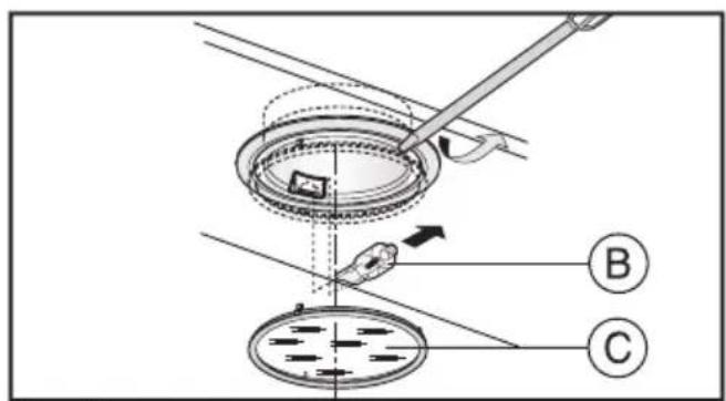
- Replacing halogen light bulbs (Fig.6A):
To replace the halogen light bulbs B, remove the glass pane C using a lever action on the relevant cracks.
Replace the bulbs with new ones of the same type. Caution: do not touch the light bulb with bare hands.
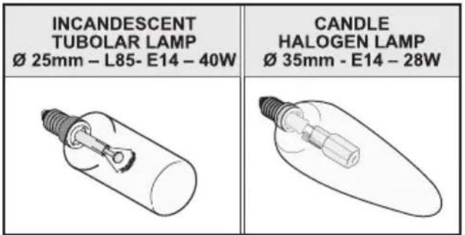
- Replacing the halogen/incandescent lamps (Fig.6B): Only use lamps of the same type and wattage installed on the device.
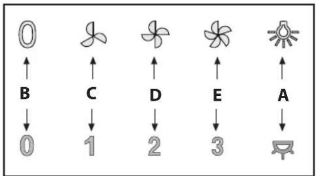
- Commands (Fig.9) mechanical the key symbols are explained below:
A = LIGHT
B = OFF
C = SPEED I
D = SPEED II
E = SPEED III.
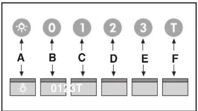
- Commands luminous (Fig.10) the key symbols are explained below:
A = LIGHT
B = OFF
C = SPEED I
D = SPEED II
E = SPEED III
F = AUTOMATIC STOP TIMER - 15 minutes (*)
If your appliance does not have the INTENSIVE speed function, press key E for two seconds and it will be activated for 10 minutes after which it will return to the previously set speed. When the function is active the LED flashes. To interrupt it before the 10 minutes have expired press key E again.
By pressing key F for two seconds (with the hood switched off) the "clean air" function is activated. This function switches the appliance on for ten minutes every hour at the first speed. As soon as this function is activated the motor starts up at the first speed for ten minutes. During this time key F and key C must flash at the same time. After ten minutes the motor switches off and the LED of key F remains switched on with a fixed light until the motor starts up again at the first speed after fifty minutes and keys F and C start to flash again for ten minutes and so on. By pressing any key for the exclusion of the hood light the hood will return immediately to its normal functioning (e.g. if key D is pressed the "clean air" function is deactivated and the motor moves to the 2nd speed straight away. By pressing key B the function is deactivated).
(*) The "AUTOMATIC STOP TIMER" delays stopping of the hood, which will continue functioning for 15 minutes at the operating speed set at the time this function is activated.
- Anti-grease/active charcoal filters saturation:
- When the A key flashes with a 2 second frequency the anti-grease filters must be washed.
- When the A key flashes with a 0.5 second frequency the active carbon filters must be replaced or washed depending on the type of filter.
Once the clean filter has been put back one must reset the electronic memory by pressing the A key for approximately 5 seconds until it stops flashing.
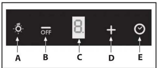
- Commands (Fig.11):
Push-button A = On/off lights switch.
Push-button B = On/off cooker hood switch. The appliance switches on at speed level 1, If the cooker hood is on depress the push-button for 2 sec. to switch off the cooker hood. If the cooker hood is at speed level 1 it will not be necessary to depress the push-button to switch the cooker hood off. Decreases the motor speed.
Display C = Indicates the motor speed level selected and activates the timer.
Push-button D = Switches on the cooker hood. Increases the motor speed. Touching the key at 3rd speed, the intensive function runs for 10', then the appliance go back to work at the original speed. During this function the display blinks.
Key E = The Timer times the functions on activation for 15 minutes, after which they are switched off. The Timer is deactivated by re-pressing Key E. When the Timer is activated the decimal point must flash on the display. The Timer cannot be activated if the intensive speed is functioning.
The "clean air" function is activated by pressing key E for 2 seconds when the appliance is switched off.
This switches the motor on for 10 minutes every hour at the first speed.
During functioning a rotary movement of the peripheral segments must be visualised on the display. When this time has passed the motor switches off and the fixed letter "C" must be visualised on the display until the motor re-starts after 50 minutes for another 10 minutes and so on. Press any key apart from the light keys to return to normal functioning. Press key E to deactivate the function.
• Active carbon/grease filter saturation:
- When display item C flashes, at a speed where it alternates with the letter F (e.g. 1 and F), the grease filters must be washed.
- When display item C flashes, at a speed where it alternates with the letter A (e.g. 1 and A), the active carbon filters must be replaced or washed depending on the type of filter.
After the clean filter has been positioned correctly, the electronic memory must be reset by pressing button A for approximately 5 seconds, until the indication F or A shown on the display C stops flashing.
- Mechanical controls (Fig.12): the symbols are as follows:
A= LIGHT / ON-OFF key
B= OFF /FIRST SPEED key
C= SECOND SPEED key
D = THIRD SPEED key
If the hood is shut off at first, second or third speed, when it is turned back on, it will start at the same speed it was in when switched off.
- Commands (Fig.13):
A = Light Key Turn on/off lights.
B = ON/OFF Key Turn on/off the hood.
The equipment switches on at the 1st speed.
To turn off the hood press key B.
C = Display Indicates the speed of the selected motor and activation of the timer.
D = Key Increases and decreases the speed of the motor with a cyclical pattern, 1^-2^-3^ ... 1^-2^-3^ speed.
By pressing the key for 3 seconds the INTENSE function comes into operation for 6 minutes, on the C display the number 4 starts flashing.
At the end of the minutes the engine will start operating at the previously set speed.
To deactivate the intense speed, before the set time, press the B key and the hood turns off, but not if the lights are on.
E = Timer key With any speed entered (excluding Intense speed) by pressing the key the timer function is activated for 15 min. At the end of the count the hood turns off (motor and any lights that are on).
To turn off the Timer function, before the pre-set time, press the B key and the hood turns off, or by pressing the timer key again it turns off but the hood continues to operate.
• Saturation Active carbon/Anti-grease filters:
- After 30 h of operation, with the hood ON on display C, the letter F starts to flash which means that the anti-grease filters have to be washed.
Once the clean filter is replaced you must reset the electronic memory, with the hood off press key B and D for 5 sec. until the display C shows the letter F fixed for 2 sec.
-After 120 h of operation, with the hood ON on display C the letter C starts to flash which means that the carbon filters have to be washed or replaced.
Once the clean filter is replaced you must do a double re-set so with the hood off press key B and D for 5 sec. until the display C shows the letter F fixed for 2 sec.
Repeat and press key B and D for 5 sec. until display C shows the letter C fixed for 2 sec..
- Commands(Fig.14)
A = ON/OFF key
Turns the hood on/off.
By pressing key A the LED flashes for 2 sec. then remains fixed and the equipment starts in 1° speed.
To turn the hood off press key A again, the LED flashes for 2 sec. then it turns off.
B = FIRST SPEED KEY
C = SECOND SPEED Key/TIMER function
- Key C also activates the TIMER function.
- The key flashes for the full duration of the TIMER.
- With any speed entered (excluding Intense speed where applicable) by pressing C for about 3 seconds the TIMER function is activated for 15 min. At the end of the count the hood turns off (motor and any lights that are on).
- To deactivate the Timer function, before the pre-set time, press any key except the F key for ON/OFF Lights.
D = THIRD SPEED key/ INTENSE SPEED Function
- Key D also activates the INTENSE SPEED function.
- The key flashes for the full duration of the INTENSE SPEED function.
- By pressing the key for 3 seconds the INTENSE function comes on for 6 minutes.
- At the end of the minutes the engine will start operating at the previously set speed.
To deactivate the intense speed, before the pre-set time, press any key except the F key for ON/OFF Lights.
Attention! Some models only work up to the 3rd speed and, therefore, do not have the intense function.
E=ON/OFF LIGHTS key
- Saturation Active carbon/Anti-grease filters:
-When the hood is on the LED corresponding to the A and B keys flash, the anti-grease filters must be washed.
Once the clean filter is put back the electronic memory must be reset, with the hood off press A for 5 sec., the reset is confirmed by a flashing of the LED A and B.
-When the hood is on the LED corresponding to C and E flash, the carbon filters must be washed.
Once the clean filter is put back the electronic memory must be reset, with the hood off press A for 5 sec., the reset is confirmed by a flashing of the LED C and E.
THE MANUFACTURER DECLINES ALL RESPONSIBILITY FOR EVENTUAL DAMAGES CAUSED BY BREACHING THE ABOVE WARNINGS.
NEDERLANDS

ALGEMEEN
INSTALLATIE INSTRUCTIES
C = knop EERSTE SNELHEID
D = knop TWEEDW DERDE SNELHEID
E = knop DERDE SNELHEID.
D = knop TWEEDW DERDE SNELHEID
E = knop DERDE SNELHEID
F = knop TIMER AUTOMATISCHE ONDERBREKING na 15 minuten (*)
- Commando's (Fig.13):
- Commando's (Fig.14):
A = ON/OFF-toets
Tecla A = Acende/apaga as luzes.
A = Tecla Luzes Liga/desliga as luzes.
B = Tecla ON/OFF Liga/desliga o exaustor.
A = tast for BELYSNING
B = tast for OFF
C = tast for F∅RSTE HASTIGHED
D = tast for ANDEN HASTIGHED
E = tast for TREDJE HASTIGHED.
A = tast for BELYSNING
B = tast for OFF
C = tast for F∅RSTE HASTIGHED
D = tast for ANDEN HASTIGHED
E = tast for TREDJE HASTIGHED
F = tast for TIMER AUTOMATISK STOP 15 minutter (*)
C= tast for ANDEN HASTIGHED
D = tast for TREDJE HASTIGHED
B = Tast F∅RSTE HASTIGHED
E=VALOJEN ON/OFF-painike
A = tast for BELYSNING
B = tast for OFF (AV)
C = tast for F∅RSTE HASTIGHET
D = tast for ANNEN HASTIGHET
E = tast for TREDJE HASTIGHET.
A = tast for BELYSNING
B = tast for OFF (AV)
C = tast for F∅RSTE HASTIGHET
D = tast for ANNEN HASTIGHET
E = tast for TREDJE HASTIGHET
F = tast TIDSURE AUTOMATISK STOPP 15 minutter (*)
A= tast for LYS / ON-OFF
B= tast for OFF / F∅RSTE HASTIGHET
C= tast for ANDRE HASTIGHET
D = tast for TREDJE HASTIGHET
Hvis hetten slukkes när den er plassert på første, andre eller tredje hastighet, vil den starte ved samme hastighet när den slås på igjen.
• Kommandoer (Fig.13):
C = knapp FÖRSTA HASTIGHET
D=knapp ANDRA HASTIGHET
E= knapp TREDJE HASTIGHET.
C = knapp FÖRSTA HASTIGHET
D=knapp ANDRA HASTIGHET
E=knapp TREDJE HASTIGHET
F = TIMER FÖR AUTOMATISK AVSTÄNGNING EFTER 15 minuter (**)
E=Knapp ON/OFF LAMPOR