C12FDHB - Saw METABO - Free user manual and instructions
Find the device manual for free C12FDHB METABO in PDF.
User questions about C12FDHB METABO
0 question about this device. Answer the ones you know or ask your own.
Ask a new question about this device
Download the instructions for your Saw in PDF format for free! Find your manual C12FDHB - METABO and take your electronic device back in hand. On this page are published all the documents necessary for the use of your device. C12FDHB by METABO.
USER MANUAL C12FDHB METABO
SAFETY INSTRUCTIONS AND INSTRUCTION MANUAL
Read and understand all of the safety precautions, warnings and operating instructions in the Instruction Manual before operating or maintaining this power tool. Most accidents that result from power tool operation and maintenance are caused by the failure to observe basic safety rules or precautions. An accident can often be avoided by recognizing a potentially hazardous situation before it occurs, and by observing appropriate safety procedures. Basic safety precautions are outlined in the “SAFETY” section of this Instruction Manual and in the sections which contain the operation and maintenance instructions. Hazards that must be avoided to prevent bodily injury or machine damage are identifi ed by WARNINGS on the power tool and in this Instruction Manual. NEVER use this power tool in a manner that has not been specifi cally recommended by metabo HPT.
MEANINGS OF SIGNAL WORDS
WARNING indicates a potentially hazardous situations which, if ignored, could result in death or serious injury. CAUTION indicates a potentially hazardous situations which, if not avoided, may result in minor or moderate injury, or may cause machine damage. NOTE emphasizes essential information.
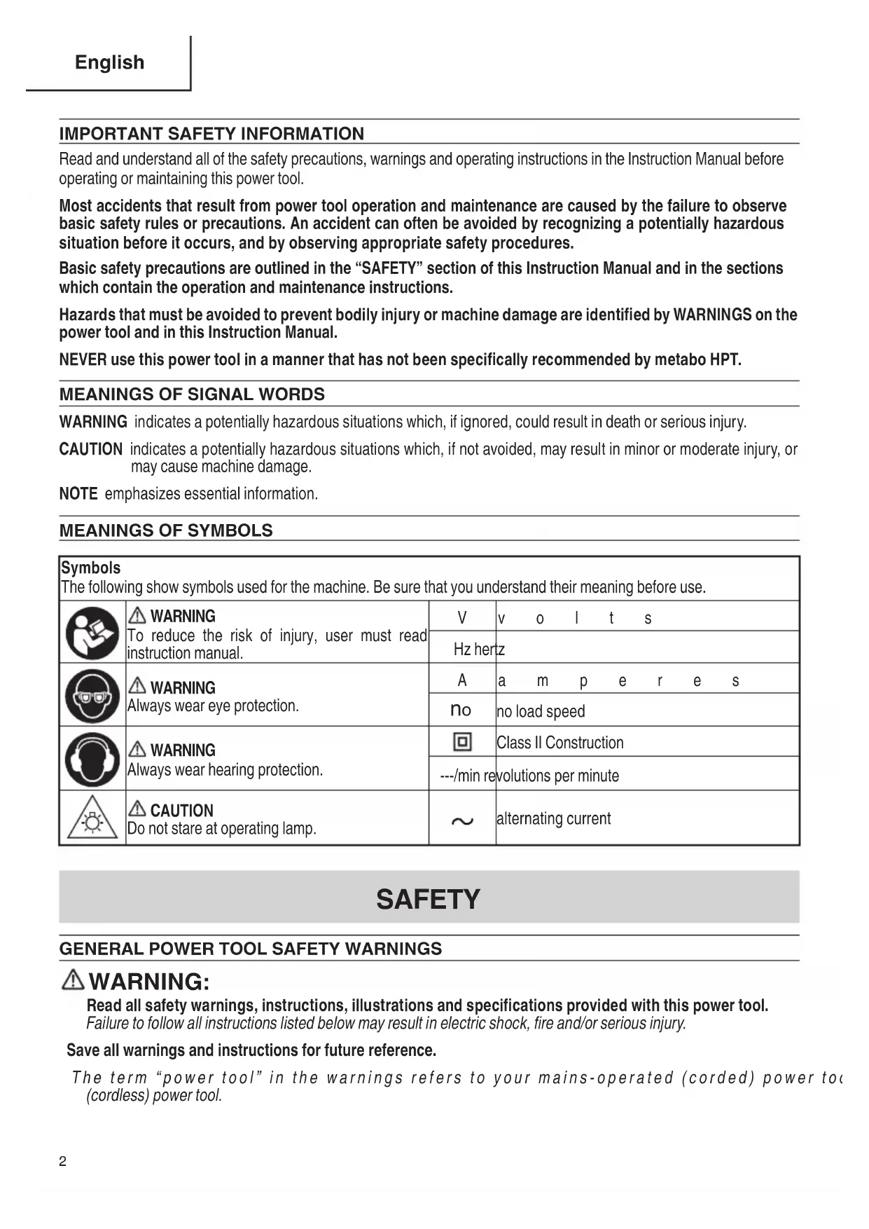
Symbols The following show symbols used for the machine. Be sure that you understand their meaning before use. WARNING To reduce the risk of injury, user must read instruction manual. Vvolts Hz hertz WARNING Always wear eye protection. Aamperes
no load speed WARNING Always wear hearing protection. Class II Construction ---/min revolutions per minute CAUTION Do not stare at operating lamp. alternating current SAFETY
Read all safety warnings, instructions, illustrations and specifi cations provided with this power tool. Failure to follow all instructions listed below may result in electric shock, fi re and/or serious injury. Save all warnings and instructions for future reference. The term “power tool” in the warnings refers to your mains-operated (corded) power tool or battery-operated (cordless) power tool. 00BookC12FDHBNANA.indb200BookC12FDHBNANA.indb2 2021/01/2910:32:102021/01/2910:32:103 English
a) Keep work area clean and well lit. Cluttered or dark areas invite accidents. b) Do not operate power tools in explosive atmospheres, such as in the presence of fl ammable liquids, gases or dust. Power tools create sparks which may ignite the dust or fumes. c) Keep children and bystanders away while operating a power tool. Distractions can cause you to lose control.
2) Electrical safety
a) Power tool plugs must match the outlet. Never modify the plug in any way. Do not use any adapter plugs with earthed (grounded) power tools. Unmodifi ed plugs and matching outlets will reduce risk of electric shock. b) Avoid body contact with earthed or grounded surfaces, such as pipes, radiators, ranges and refrigerators. There is an increased risk of electric shock if your body is earthed or grounded. c) Do not expose power tools to rain or wet conditions. Water entering a power tool will increase the risk of electric shock. d) Do not abuse the cord. Never use the cord for carrying, pulling or unplugging the power tool. Keep cord away from heat, oil, sharp edges or moving parts. Damaged or entangled cords increase the risk of electric shock. e) When operating a power tool outdoors, use an extension cord suitable for outdoor use. Use of a cord suitable for outdoor use reduces the risk of electric shock. f) If operating a power tool in a damp location is unavoidable, use a residual current device (RCD) protected supply. Use of an RCD reduces the risk of electric shock.
a) Stay alert, watch what you are doing and use common sense when operating a power tool. Do not use a power tool while you are tired or under the infl uence of drugs, alcohol or medication. A moment of inattention while operating power tools may result in serious personal injury. b) Use personal protective equipment. Always wear eye protection. Protective equipment such as a dust mask, non- skid safety shoes, hard hat or hearing protection used for appropriate conditions will reduce personal injuries. c) Prevent unintentional starting. Ensure the switch is in the off -position before connecting to power source and/or battery pack, picking up or carrying the tool. Carrying power tools with your fi nger on the switch or energising power tools that have the switch on invites accidents. d) Remove any adjusting key or wrench before turning the power tool on. A wrench or a key left attached to a rotating part of the power tool may result in personal injury. e) Do not overreach. Keep proper footing and balance at all times. This enables better control of the power tool in unexpected situations. f) Dress properly. Do not wear loose clothing or jewellery. Keep your hair, clothing and gloves away from moving parts. Loose clothes, jewellery or long hair can be caught in moving parts. g) If devices are provided for the connection of dust extraction and collection facilities, ensure these are connected and properly used. Use of dust collection can reduce dust-related hazards. h) Do not let familiarity gained from frequent use of tools allow you to become complacent and ignore tool safety principles. A careless action can cause severe injury within a fraction of a second.
4) Power tool use and care
a) Do not force the power tool. Use the correct power tool for your application. The correct power tool will do the job better and safer at the rate for which it was designed. b) Do not use the power tool if the switch does not turn it on and off . Any power tool that cannot be controlled with the switch is dangerous and must be repaired. c) Disconnect the plug from the power source and/or remove the battery pack, if detachable, from the power tool before making any adjustments, changing accessories, or storing power tools. Such preventive safety measures reduce the risk of starting the power tool accidentally. 00BookC12FDHBNANA.indb300BookC12FDHBNANA.indb3 2021/01/2910:32:102021/01/2910:32:104 English d) Store idle power tools out of the reach of children and do not allow persons unfamiliar with the power tool or these instructions to operate the power tool. Power tools are dangerous in the hands of untrained users. e) Maintain power tools and accessories. Check for misalignment or binding of moving parts, breakage of parts and any other condition that may aff ect the power toolʼs operation. If damaged, have the power tool repaired before use. Many accidents are caused by poorly maintained power tools. f) Keep cutting tools sharp and clean. Properly maintained cutting tools with sharp cutting edges are less likely to bind and are easier to control. g) Use the power tool, accessories and tool bits etc. in accordance with these instructions, taking into account the working conditions and the work to be performed. Use of the power tool for operations diff erent from those intended could result in a hazardous situation. h) Keep handles and grasping surfaces dry, clean and free from oil and grease. Slippery handles and grasping surfaces do not allow for safe handling and control of the tool in unexpected situations.
a) Have your power tool serviced by a qualifi ed repair person using only identical replacement parts. This will ensure that the safety of the power tool is maintained. PRECAUTION Keep children and infi rm persons away. When not in use, tools should be stored out of reach of children and infi rm persons.
SAFETY INSTRUCTIONS FOR MITER SAWS
a) Miter saws are intended to cut wood or wood-like products, they cannot be used with abrasive cut- off wheels for cutting ferrous material such as bars, rods, studs, etc. Abrasive dust causes moving parts such as the lower guard to jam. Sparks from abrasive cutting will burn the lower guard, the kerf insert and other plastic parts. b) Use clamps to support the workpiece whenever possible. If supporting the workpiece by hand, you must always keep your hand at least 100 mm from either side of the saw blade. Do not use this saw to cut pieces that are too small to be securely clamped or held by hand. If your hand is placed too close to the saw blade, there is an increased risk of injury from blade contact. c) The workpiece must be stationary and clamped or held against both the fence and the table. Do not feed the workpiece into the blade or cut "freehand" in any way. Unrestrained or moving workpieces could be thrown at high speeds, causing injury. d) Never cross your hand over the intended line of cutting either in front or behind the saw blade. Supporting the workpiece “cross handed” i.e. holding the workpiece to the right of the saw blade with your left hand or vice versa is very dangerous. e) Do not reach behind the fence with either hand closer than 100 mm from either side of the saw blade, to remove wood scraps, or for any other reason while the blade is spinning. The proximity of the spinning saw blade to your hand may not be obvious and you may be seriously injured. f) Inspect your workpiece before cutting. If the workpiece is bowed or warped, clamp it with the outside bowed face toward the fence. Always make certain that there is no gap between the workpiece, fence and table along the line of the cut. Bent or warped workpieces can twist or shift and may cause binding on tile spinning saw blade while cutting. There should be no nails or foreign objects in the workpiece. g) Do not use the saw until the table is clear of all tools, wood scraps, etc., except for the workpiece. Small debris or loose pieces of wood or other objects that contact the revolving blade can be thrown with high speed. h) Cut only one workpiece at a time. Stacked multiple workpieces cannot be adequately clamped or braced and may bind on the blade or shift during cutting.
i) Ensure the miter saw is mounted or placed on a
level, fi rm work surface before use. A level and fi rm work surface reduces the risk of the miter saw becoming unstable. j) Plan your work. Every time you change the bevel or miter angle setting, make sure the adjustable fence is set correctly to support the workpiece and will not interfere with the blade or the guarding system. 00BookC12FDHBNANA.indb400BookC12FDHBNANA.indb4 2021/01/2910:32:112021/01/2910:32:115 English Without turning the tool “ON” and with no workpiece on the table, move the saw blade through a complete simulated cut to assure there will be no interference or danger of cutting the fence. k) Provide adequate support such as table extensions, saw horses, etc. for a workpiece that is wider or longer than the table top. Workpieces longer or wider than the miter saw table can tip if not securely supported. If the cut-off piece or workpiece tips, it can lift the lower guard or be thrown by the spinning blade. l) Do not use another person as a substitute for a table extension or as additional support. Unstable support for the workpiece can cause the blade to bind or the workpiece to shift during the cutting operation pulling you and the helper into the spinning blade. m) The cut-off piece must not be jammed or pressed by any means against the spinning saw blade. If confi ned, i.e. using length stops, the cut-off piece could get wedged against the blade and thrown violently. n) Always use a clamp or a fixture designed to properly support round material such as rods or tubing. Rods have a tendency to roll while being cut, causing the blade to "bite" and pull the work with your hand into the blade. o) Let the blade reach full speed before contacting the workpiece. This will reduce the risk of the workpiece being thrown. p) If the workpiece or blade becomes jammed, turn the miter saw off . Wait for all moving parts to stop and disconnect the plug from the power source and/or remove the battery pack. Then work to free the jammed material. Continued sawing with a jammed workpiece could cause lass of control or damage to the miter saw. q) After fi nishing the cut, release the switch, hold the saw head down and wait for the blade to stop before removing the cut-off piece. Reaching with your hand near the coasting blade is dangerous. r) Hold the handle fi rmly when making an incomplete cut or when releasing the switch before the saw head is completely in the down position. The braking action of the saw may cause the saw head to be suddenly pulled downward, causing a risk of injury. s) When the saw head is in the down position, never release the hand that is gripping the handle. Doing so could snap the saw head up, forcing the tool to fall and possibly cause injury.
WARNING The following specifi c operating instructions must be observed when using this POWER TOOL in order to avoid injury: DO’s
ALWAYS OBSERVE THE FOLLOWING RULES TO
ASSURE SAFE USE OF THIS TOOL:
1. Review this Manual and familiarize yourself with the
safety rules and operating instructions for this POWER TOOL before attempting to use it.
2. Remove all packing materials attached or connected
to the tool before attempting to operate it.
3. Always confi rm that the POWER TOOL is clean before
4. Always wear snug-fi tting clothing, non-skid footwear
(preferably with steel toes) and eye protection when operating the POWER TOOL.
5. Always handle the POWER TOOL carefully. If the
POWER TOOL falls or strikes against a hard object, it might become deformed or cracked or sustain other damage.
6. Always cease operating the saw at once, if you notice
any abnormality whatsoever.
7. Always confirm that all components are mounted
properly and securely before using the tool.
8. When replacing the saw blade, always confi rm that the
rpm rating of the new blade is correct for use on this tool.
9. Always shut off the power and wait for the saw blade to
completely stop rotating before doing any maintenance or adjustments.
10. Always clamp or otherwise secure the workpiece to the
fence; otherwise the workpiece might be thrust form the table and cause bodily harm.
11. During miter or bevel cutting, always wait for the rotation
of the blade to stop completely before lifting the saw blade.
12. Always make a trial run fi rst before attempting any new
13. Always handle the saw blade with care when
dismounting and mounting it.
14. Always confi rm that the workpiece is free of nails or
other foreign objects before beginning a cut.
15. Always keep your hands out of the path of the saw
16. Always confi rm that the lower guard is in the proper
place before using the saw.
17. Inspect the tool power cords periodically.
00BookC12FDHBNANA.indb500BookC12FDHBNANA.indb5 2021/01/2910:32:112021/01/2910:32:116 English
18. Always confi rm that the proper lengths and types of
extension cords are being utilized, if necessary, before starting the tool.
19. Always confi rm that the motor air vents are fully open
before using the tool.
20. Always wait until the motor has reached full speed
before starting a cut.
21. Always keep the handles dry, clean and free of oil and
grease. Hold the tool fi rmly when in use.
22. Always use outboard stands to provide support for long
workpieces that overhang the table of the compound miter saw.
23. Always operate the tool after ensuring the workpiece
is fi xed properly with a vise assembly.
24. The operating instructions provided with the tool shall
direct the user to secure the tool to supporting structure if, during normal operation, there is a tendency for the tool to tip over, slide, or walk on the supporting surface.
25. Ensure before each cut that the machine is stable.
26. If the saw blade should become jammed, switch the
machine off and hold the workpiece until the saw blade comes to a complete stop. To prevent kickback, the workpiece may not be moved until after the machine has come to a complete stop. Correct the cause for the jamming of the saw blade before restarting the machine.
27. Use only saw blades that are marked with a maximum
permitted speed equal or higher than the no-load speed marked on the POWER TOOL.
28. Use only a saw blade diameter in accordance with the
markings on the POWER TOOL.
1. Never operate the POWER TOOL unless you fully
understand the operating instructions contained in this Manual.
2. Never leave the POWER TOOL unattended without
fi rst unplugging the power cord.
3. Never operate the POWER TOOL when you are
tired, after you have taken any medications, or have consumed any alcoholic beverages.
5. Never operate the tool while wearing loose clothing, a
necktie or jewelry, or while your hair is uncovered, to protect against getting caught in the moving machinery.
6. Never reach around the saw blade.
7. Never touch any moving parts, including the blade,
while the saw is in use.
8. Never remove any safety devices or blade guards; use
of the tool without them would be hazardous.
9. Never lock the lower guard; always confi rm that it slides
smoothly before using the tool.
10. Never damage the power cord of the tool.
11. Never attempt to move a plugged-in POWER TOOL
while your fi nger is on the starting switch.
12. Never use the POWER TOOL if the starting switch does
not turn on and off properly.
13. Never use the POWER TOOL if the plastic housing or
the handle is cracked or deformed.
14. Never use the POWER TOOL near fl ammable liquids
or gases because sparking can cause an explosion.
15. Never clean plastic components with solvents because
the plastic may dissolve.
16. Never operate the saw unless all the blade guards are
17. Never raise the saw blade from the workpiece until it
has fi rst come to a complete stop.
18. Never place your limbs inside of the line next to warning
sign “ ” while the tool is being operated. This may cause hazardous conditions.
19. Never use abrasive type blades on this saw.
20. Never expose to rain or use in damp locations.
23. Do not stand in a line with the saw blade In front of the
machine. Always stand aside of the saw blade. This protects your body against possible kickback. Keep hands, fi ngers and arms away from the rotating saw blade.
24. Do not cross your arms when operating the tool arm.
1. Always wear eye protection when using the compound
2. Always keep hands out of the path of the saw blade.
3. Never operate the saw without the guards in place.
4. Never perform any freehand operation with the
5. Never reach around the saw blade.
6. Always turn off tool and wait for saw blade to stop before
moving workpiece or changing settings.
7. Always disconnect power before changing blade or
REPLACEMENT PARTS When servicing use only identical replacement parts. Repairs should be conducted only by a metabo HPT authorized service center. 00BookC12FDHBNANA.indb600BookC12FDHBNANA.indb6 2021/01/2910:32:112021/01/2910:32:117 English
USE PROPER EXTENSION CORD
Make sure your extension cord is in good condition. When using an extension cord, be sure to use one heavy enough to carry the current your product will draw. An undersized cord will cause a drop in line voltage resulting in loss of power and overheating. Table shows the correct size to use depending on cord length and nameplate ampere rating. If in doubt, use the next heavier gage. The smaller the gage number, the heavier the cord.
MINIMUM GAGE FOR CORD SETS
Total Length of Cord in Feet (Meter) 0–25 (0–7.6) 26–50 (7.9–15.2) 51–100 (15.5–30.5) 101–150 (30.8–45.7) Ampere Rating AWG More Than Not More Than 0–6 18 16 16 14 6–10 18 16 14 12 10–12 16 16 14 12 12–16 14 12 Not Recommended WARNING Avoid electrical shock hazard. Never use this tool with a damaged or frayed electrical cord or extension cord. Inspect all electrical cords regularly. Never use in or near water or in any environment where electric shock is possible.
DOUBLE INSULATION FOR SAFER OPERATION
To ensure safer operation of this power tool, metabo HPT has adopted a double insulation design. “Double insulation” means that two physically separated insulation systems have been used to insulate the electrically conductive materials connected to the power supply from the outer frame handled by the operator. Therefore, either the symbol “ ” or the words and “Double insulation” appear on the power tool or on the nameplate. Although this system has no external grounding, you must still follow the normal electrical safety precautions given in this Instruction Manual, including not using the power tool in wet environments. To keep the double insulation system eff ective, follow these precautions:
- Only metabo HPT AUTHORIZED SERVICE CENTER should disassemble or assemble this power tool, and only genuine metabo HPT replacement parts should be installed.
- Clean the exterior of the power tool only with a soft cloth moistened with soapy water and dry thoroughly.
- Never use solvents, gasoline or thinners on plastic components; otherwise the plastic may dissolve.
SAVE THESE INSTRUCTIONS
NOTE: The information contained in this Instruction Manual is designed to assist you in the safe operation and maintenance of the power tool. Some illustrations in this Instruction Manual may show details or attachments that diff er from those on your own power tool.
WARNING: Accessories for this power tool are mentioned in this Instruction
Manual. The use of any other attachment or accessory can be dangerous and could cause injury or mechanical damage. STANDARD ACCESSORIES 12" (305 mm) TCT Saw blade (1 piece) (For wood)(No. of teeth 40 Code No. 377326) Vise Assembly (1 piece)For how to use, refer to page 23. Dust bag (1 piece)For how to use, refer to page 13. 6 mm hex. bar wrench Sub fence (L) (1 piece)For how to use, refer to page 19. Fig. 3 OPTIONAL ACCESSORIES...sold separately Extension holder and Stopper (Code No. 377095) Crown molding Vise Ass’y (Code No. 339660) Crown molding Stopper (L) (Code No. 339730) Crown molding Stopper (R) (Code No. 339731) NOTE: Accessories are subject to change without any obligation on the part of the metabo HPT. 00BookC12FDHBNANA.indb1100BookC12FDHBNANA.indb11 2021/01/2910:32:122021/01/2910:32:1212 English APPLICATIONS Wood and aluminum sash.
PREPARATION BEFORE OPERATION
Make the following preparations before operating the power tool:
1. Remove all packing materials attached or connected to the tool before attempting to operate
10-7/32" (259.75 mm) 9-23/32" (247 mm) 10-7/32" (259.75 mm) 9-23/32" (247 mm) 11/32" (9 mm) 4 holes 13" (330 mm) 1" (25 mm) thick bench Work bench 5/16" (8 mm) nut 5/16" (8 mm) boltBase Fig. 4 Attach the power tool to a level, horizontal work bench in accordance with Fig. 4. Select 5/16" (8 mm) diameter bolts suitable in length for the thickness of the work bench. Bolt length should be at least 1-9/16" (40 mm) plus the thickness of the work bench. For example, use 2-9/16" (65 mm) or larger bolts for a 1" (25 mm) thick work bench. 00BookC12FDHBNANA.indb1200BookC12FDHBNANA.indb12 2021/01/2910:32:132021/01/2910:32:1313 English
3. Releasing the locking pin
Pull Locking pin Handle Fig. 5 When the power tool is prepared for shipping, its main parts are secured by a locking pin. Move the handle slightly so that the locking pin can be disengaged. NOTE: Lowering the handle slightly will enable you to disengage the locking pin more easily and safely. The lock position of the locking pin is for carrying and storage only.
4. Installing the sub fence (L), dust bag, extension holder, stopper and vises
(The extension holder and stopper are optional accessories.) Attach the sub fence (L), dust bag and vise assembly as indicated in Fig. 1 and Fig. 2. Install the dust bag onto the duct on the miter saw. Fit the supprot bar of the dust bag and the duct together. To empty the dust bag, pull out the dust bag assembly from the duct. Open zipper on underside of bag and empty into waste container. Check frequently and empty the dust bag before it gets full. CAUTION: Empty the dust bag frequently to prevent the duct and the lower guard from becoming clogged. Sawdust will accumulate more quickly than normal during bevel cutting.
WARNING: Do not use this saw to cut and/or sand metals. The hot chips or
sparks may ignite saw dust from the bag material. (Attach the vise assembly as shown in Fig. 1, Fig. 2 and Fig. 18.) Fig. 6 Duct Dust bag 00BookC12FDHBNANA.indb1300BookC12FDHBNANA.indb13 2021/01/2910:32:132021/01/2910:32:1314 English BEFORE USING
1. Make sure the power source is appropriate for the tool.
WARNING: Never connect the power tool unless the available AC power
source is of the same voltage as that specifi ed on the nameplate of the tool. Never connect this power tool to a DC power source.
2. Make sure the trigger switch is turned OFF.
WARNING: If the power cord is connected to the power source with the
trigger switch turned ON the power tool will start suddenly and can cause a serious accident.
3. Check the saw blade for visible defects.
Confi rm that the saw blade is free of cracks or other visible damage.
4. Confi rm that the saw blade is attached securely to the power tool.
Using the supplied 6 mm hex. bar wrench, tighten the 8 mm bolt on the saw blade spindle to secure the saw blade. For details, see Fig. 37-a, Fig. 37-b, Fig. 37-c and Fig. 37-d in the section on “SAW BLADE MOUNTING AND DISMOUNTING”.
5. Check the lower guard for proper operation.
Lower guard is designed to protect the operator from coming into contact with the saw blade during operation of the tool. Always check that the lower guard moves smoothly and covers the saw blade properly.
6. Confi rm the position of the spindle lock before using the tool.
After installing the saw blade, confi rm that the spindle lock has been returned to the released position before using the power tool (see Fig. 2).
7. Check the Power Receptacle.
To prevent overheating, accidental stopping or intermittent operation, confi rm that the power cord plug fi ts properly in the electrical receptacle and does not fall out after it is inserted. Repair or replace the receptacle if it is faulty. Fig. 7 Lower guard 00BookC12FDHBNANA.indb1400BookC12FDHBNANA.indb14 2021/01/2910:32:142021/01/2910:32:1415 English
8. Confi rm the tool’s power cord is not damaged.
Repair or replace the power cord if an inspection indicates that it is damaged
Always wear eye protection with side shields that meets the requirements of ANSI Standard Z87.1. Ordinary eyeglasses do not provide adequate protection because they do not contain impact resistant safety glass.
WARNING: Operating the tool without wearing proper eye protection may
result in serious injury.
This tool is equipped with an electric brake which will typically stop the blade within 5 seconds after the trigger switch is released. Occasionally, there will be a delay in the brake engaging which will result in a longer blade stopping time. On rare occasions, the brake may not engage at all and the saw blade will coast to a stop. If the brake fails to engage frequently, depress and release the trigger switch to turn the tool on and off 4 or 5 times. If the brake still does not engage, have the tool serviced at a metabo HPT authorized service center. Always confi rm that the saw blade has completely stopped before raising it from the workpiece. The brake is not a substitute for a properly functioning lower guard. Check the function of the lower guard before each use. Serious personal injury may occur if the lower guard does not move smoothly and cover the blade properly.
WARNING: Please be aware of the reaction of the Motor Head (Fig. 1) when
the brake is activated. Braking causes the Motor Head to jerk downward and the user should be prepared for this reaction, especially when the trigger switch is released before the blade is completely down. Failure to be familiar with, and prepared for, the operational characteristics of the tool may cause serious injury. AFTER CONNECTING THE POWER PLUG TO AN APPROPRIATE AC POWER SOURCE, CHECK THE OPERATION OF THE TOOL AS FOLLOWS:
After confi rming that no one is standing behind, the power tool start and confi rm that no operating abnormalities exist before attempting a cutting operation.
12. Inspect the rotating stability of the saw blade.
For precise cutting, rotate the saw blade and check for defl ection to confi rm that the blade is not noticeably unstable; otherwise vibrations might occur and cause an accident. 00BookC12FDHBNANA.indb1500BookC12FDHBNANA.indb15 2021/01/2910:32:142021/01/2910:32:1416 English BEFORE CUTTING
1. Checking the saw blade lower limit position
Check that the saw blade can be lowered 49 mm to 50 mm below the table insert. When you replace a saw blade with a new one, adjust the lower limit position so that the saw blade will not cut the turntable or complete cutting cannot be done. To adjust the lower limit position of the saw blade, follow the procedure (1) indicated below. (Fig. 8) Furthermore, when changing the position of a 6 mm depth adjustment screw that serves as a lower limit position stopper of the saw blade. (1) Turn the 6 mm depth adjustment screw, change the height where the screw head and the hinge contacts, and adjust the lower limit position of the saw blade. The lower limit position is raised when the 6 mm depth adjustment screw is turned clockwise. NOTE: Confi rm that the saw blade is adjusted so that it will not cut into the turntable.
Before the power tool is shipped from the factory, it is adjusted for 0°, right angle, left 33.9° & 45° bevel cutting angle and right 33.9° & 45° bevel cutting angle with the 6 mm set screw, 6 mm hex. socket screw (A) and 6 mm hex. socket screw (B). When changing the adjustment, change the height of the 6 mm set screw, 6 mm hex. socket screw (A) or 6 mm hex. socket screw (B) by turning them. (Fig. 9-a, 9-b) When changing the height of the 6 mm set screw, using the 3 mm hex key to turn it. When changing the height of the 6 mm hex. socket screw, using the 5 mm hex key to turn it. When changing the bevel angle to the right 45°, press the set button on the direction shown in Fig. 9-b and incline the motor head to the right. When adjusting the motor head to 0°, always return the set button to its released position. NOTE: To obtain right bevel angles, press the set button and tilt the saw to the desired angle. When obtain left or right 45° bevel cutting angle, do not need to adjust the left & right 33.9° bevel cutting angle. Saw bladeHingeTurntable6 mm depth adjustment screw Fig. 8 00BookC12FDHBNANA.indb1600BookC12FDHBNANA.indb16 2021/01/2910:32:142021/01/2910:32:1417 English Fig. 9-a Fig. 9-b Angle block (B) Angle block (A) Set button Press Angle block (A) Angle block (B) Indicator (for right bevel scale) 6 mm hex. socket screw (B) Indicator (for left bevel scale) 6 mm hex. socket screw (A) 6 mm set screw
3. Installing the holders ... (Optional accessory)
Fig. 10 Steel square Base surface 6 mm knob bolt (Optional accessory) Holder (Optional accessory) 6 mm wing nut (Optional accessory) Height adjustment bolt 6 mm (Optional accessory) The holders help keep longer workpieces stable and in place during the cutting operation. (1) As indicated in Fig. 10, use a steel square for aligning the upper edge of the holders with the base surface. Loosen the 6 mm knob bolt. Turn a height adjustment bolt 6 mm, and adjust the height of the holder. (2) After adjustment, fi rmly tighten the 6 mm wing nut and fasten the holder with the 6 mm knob bolt (optional accessory). If the length of height adjustment bolt 6 mm is insuffi cient, spread a thin plate beneath. Make sure the end of height adjustment bolt 6 mm does not protrude from the holder. 00BookC12FDHBNANA.indb1700BookC12FDHBNANA.indb17 2021/01/2910:32:152021/01/2910:32:1518 English
4. Stopper for precision cutting ... (Stopper and holder are optional accessory)
The stopper facilitates continuous precision cutting in lengths of 11-27/64" to 18" (290 mm to 460 mm). To install the stopper, attach it to the holder with the 6 mm wing bolt as shown in Fig. 11.
slide the sub fence (R) outward. Failure to do so may result in the main body or saw blade coming into contact with the sub fence (R) and causing injury. 8 mm knob bolt 6 mm screw Fence (R) Sub fence (R) Fig. 12-a This power tool is equipped with a sub fence (R). In the case of direct angle cutting and left bevel angle cutting, use the sub fence (R). Then, you can realize stable cutting of the material with a wide back face. When right bevel angle cutting, loosen the 8 mm knob bolt, then slide sub fence (R) outward, as shown in Fig. 12-a. If unable to get enough clearance with the motor head because the bevel angle is too large, loosen the 6 mm screw and remove the sub fence (R). NOTE: When transporting the saw, always secure the sub fence (R) in the collapsed position and lock it. Workpiece Stopper (Optional accessory) Holder (Optional accessory) 6 mm wing nut (Optional accessory) Height adjustment bolt 6 mm (Optional accessory) 6 mm wing bolt (Optional accessory) Fig. 11 00BookC12FDHBNANA.indb1800BookC12FDHBNANA.indb18 2021/01/2910:32:152021/01/2910:32:1519 English
6. Confi rmation for use of sub fence (L) (Fig. 12-b)
WARNING: When left bevel angle cutting, loosen the 8 mm knob bolt, then
slide the sub fence (L) outward. Failure to do so may result in the main body or saw blade coming into contact with the sub fence (L) and causing injury. Fig. 12-b 8 mm knob bolt Sub fence (L) Fence (L) 6 mm screw This power tool is equipped with a sub fence (L). In the case of direct angle cutting and right bevel angle cutting, use the sub fence (L). Then, you can realize stable cutting of the material with a wide back face. When left bevel angle cutting, loosen the 8 mm knob bolt, then slide the sub fence (L) outward, as shown in Fig. 12-b. If unable to get enough clearance with the motor head because the bevel angle is too large, loosen the 6 mm screw and remove the sub fence (L). NOTE: When transporting the saw, always secure the sub fence (L) in the collapsed position and lock it.
7. Bevel angle 33.9°, 45°, 48°
Located deep within both sides of the base are angle block (A) and angle block (B). These angle blocks are required when sitting up the right and left bevel angles of 33.9°, 45°, or 48° on the right and left. (1) Bevel angle of 33.9° (right and left) (Fig. 13-a) Set up with angle block (A) and angle block (B) stacked, and rotate from B to direction A. After pulling out the sub fence, loosen the bevel lock handle and tilt the motor head to place either the 6 mm hex socket screw (A) (when tilted to the left) or the 6 mm hex socket screw (B) (when tilted to the right) on angle block (B). When the bevel angle is set, tighten the bevel lock handle to secure the motor head. (2) Bevel angle of 45° (right and left) (Fig. 13-b) Rotate angle block (B) on its own from A to direction B. Set angle block (A) on side A. After pulling out the sub fence, loosen the bevel lock handle and tilt the motor head to place either the 6 mm hex socket screw (A) (when tilted to the left) or the 6 mm hex socket screw (B) (when tilted to the right) on angle block (A). When the bevel angle is set, tighten the bevel lock handle to secure the motor head. 00BookC12FDHBNANA.indb1900BookC12FDHBNANA.indb19 2021/01/2910:32:152021/01/2910:32:1520 English (3) Bevel angle of 48° (right and left) (Fig. 13-c) Rotate both angle block (A) and angle block (B) from A to direction B. After pulling out the sub fence, loosen the bevel lock handle and tilt the motor head to place either the 6 mm hex socket screw (A) (when tilted to the left) or the 6 mm hex socket screw (B) (when tilted to the right) on the base surface. When the bevel angle is set, tighten the bevel lock handle to secure the motor head. BBBBAAAABevel pointer screwAngle block (B)6mm Hex. Socket Screw (A)Angle block (A) Fig. 13-a BBBB AAAA Bevel pointer screwAngle block (B)6 mm Hex. Socket Screw (A)Angle block (A) Fig. 13-b
(1) When the blade is exactly 90° (0°) to the table, loosen the bevel pointer screw using a #2 Phillips screwdriver. (2) Adjust Indicator to the “0” mark on the bevel scale and retighten the screw.
9. Quick-cam locking lever operation
If miter angles required are NOT one of the nine positive stops, the turntable can be locked at any angle between these positive stops by using the postive stop lock button and miter lock handle. Unlock the turntable by lifting up the miter lock handle, grasp the miter lock handle and pressing down on the postive stop lock button to move the table to the desired angle, then release the postive stop lock button. Press down on the miter lock handle to lock the table in position. IndicatorMiter scaleMiter lock handleUnlock Lock Postive stop lock buttonMiter detent override buttonTurntable Fig. 14 00BookC12FDHBNANA.indb2000BookC12FDHBNANA.indb20 2021/01/2910:32:162021/01/2910:32:1621 English
10. Miter detent override button (Fig. 14)
The miter detent override button allows for the table to be micro adjusted, disengaging the positive detent stops feature. When a required miter angle is close to a positive detent stop, this override prevents the wedge on the miter arm from slipping into that detent slot on the base. (1) Unlock the turntable by lifting up the miter lock handle. (2) Press down on the positive stop locking button and press the miter detent override button in, then release the positive stop locking button while pressing the miter detent override button in. The detent override is now engaged. (3) Turn the turntable to the desired angle, secure the turntable at the desired angle by pressing the miter lock handle. (4) To disengage the miter detent override button, press down again on the positive stop lock button.
11. LED lighting system (Fig. 15) [XACT CUT LED™]
CAUTION: Do not stare at operating lamp. Staring into the light beam may result in serious injury or vision loss. The LED lighting system [XACT CUT LED™] casts the shadow of the blade onto the workpiece. This results in greater accuracy of cuts and requires no adjustments. To use this feature, turn the LED light switch on. Bring the motor head down so the blade is approximately 1/4 in. (6 mm) from the workpiece. The shadow of the blade will be projected onto the workpiece, indicating where the blade teeth will make contact as the cut is made. Fig. 15 LED light switch Shadow of blade teeth projected onto workpiece 00BookC12FDHBNANA.indb2100BookC12FDHBNANA.indb21 2021/01/2910:32:162021/01/2910:32:1622 English PRACTICAL APPLICATIONS
WARNING: * To avoid personal injury, never remove or place a workpiece on
the table while the tool is being operated.
- Never place your limbs inside of the line next to warning sign while the tool is being operated. This may cause hazardous conditions (see Fig. 16). Fig. 16 Line Line Warning signWarning sign
The tool will not start unless the lock-off button is pressed while the switch is pulled back. The Lock-off button can be engaged by pressing it to right. After the switch is on, the saw blade will continue to operate as long as you pull on the trigger switch, even if you release the lock-off button. When the switch is released, the lock-off button automatically disengages to prevent inadvertent motor startup.
WARNING: To avoid injury, after completing a cut and releasing the trigger
switch, allow the blade to stop before raising the saw head.
WARNING: Never lock the Lock-off button in depressed position.
Pulling back the switch would then cause the tool to suddenly start operating, which could result in injury. Fig. 17 Lock-off buttonTrigger switch 00BookC12FDHBNANA.indb2200BookC12FDHBNANA.indb22 2021/01/2910:32:182021/01/2910:32:1823 English
2. Securing Workpiece
WARNING: Always fi rmly clamp or vise to secure the workpiece to the fence
or base; otherwise the workpiece might be thrust from the table and cause bodily harm. CAUTION: Always confi rm that the motor head (see Fig. 1) does not contact the vise assembly when it is lowered for cutting. If there is any danger that it may do so, loosen the 6 mm vice lock knob and move the vise assembly to a position where it will not contact the saw blade. (1) Using the Vise Assembly (Standard accessory) (1) The vise assembly can be mounted on the base, secure in place with 6 mm vice lock knob. (2) Turn the upper knob and securely fi x the workpiece in position (Fig. 18). (2) Using the Clamp (Commercially available) Fig. 19 Clamp For base molding with height and other materials that will not allow the use of the vise assembly (standard accessory), make sure the material is fi xed in position with commercially available clamps. (Fig. 19) Fig. 18 Vise shaft Knob Vise plateWorkpieceFence6 mm vice lock knob 00BookC12FDHBNANA.indb2300BookC12FDHBNANA.indb23 2021/01/2910:32:192021/01/2910:32:1924 English
3. Cutting Operation
(Front view)WorkpieceSaw bladeAdjusting line Fig. 20 (Front view)Marking (pre-marked)Marking (pre-marked)
Saw blade (1) As shown in Fig. 20 the width of the saw blade is the width of the cut. Therefore, slide the workpiece to the right (viewed from the operator’s position) when length ⓑ is desired, or to the left when length ⓐ is desired. Turn the LED light, project the shadow of the blade onto the workpiece, align the left side or right side of shadow of the blade with the ink line on the workpiece. (2) Once the saw blade reaches maximum speed, push the handle down carefully until the saw blade approaches the workpiece. (3) Once the saw blade contacts the workpiece, push the handle down gradually to cut into the workpiece. (4) After cutting the workpiece to the desired depth, turn the power tool OFF and let the saw blade stop completely before raising the handle from the workpiece to return it to the full retract position. CAUTION: Increased pressure on the handle will not increase the cutting speed. On the contrary, too much pressure may result in overload of the motor and/or decreased cutting effi ciency.
WARNING: * Confi rm that the trigger switch is turned OFF and the power plug
has been removed from the receptacle whenever the tool is not in use.
- Always turn the power off and let the saw blade stop completely before raising the handle from the workpiece. If the handle is raised while the saw blade is still rotating, the cut- off piece may become jammed against the saw blade causing fragments to scatter about dangerously.
- Every time one cutting or deep-cutting operation is fi nished, turn the trigger switch off , and check that the saw blade has stopped. Then raise the handle, and return it to the full retract position.
- Be absolutely sure to remove the cut material from the top of the turntable, and then proceed to the next step.
- Continued cutting operation can result in overload of the motor. Touch the motor assembly and if it's hot, stop your cutting operation at once and rest for 10 minutes or so, and then restart your cutting operation. 00BookC12FDHBNANA.indb2400BookC12FDHBNANA.indb24 2021/01/2910:32:192021/01/2910:32:1925 English
4. Miter cutting procedures
(1) Unlock the turntable by lifting up on the miter lock handle. (2) While pressing down on the positive stop lock button, grasp the miter lock handle and rotate the turntable left or right to the desired angle. (3) Once the desired miter angle is achieved, release the positive stop lock button and press down on the miter lock handle to secure the turntable into position. (4) If the desired miter angle is NOT one of the nine positive stops noted below, please see the Miter detent override button section on page 21. (5) Turn the LED light on and position the workpiece on the table for pre-alignment of your cut. CAUTION: Always check that the miter lock handle is secured and the turntable is clamped. If you attempt angle cutting without clamping the turntable, then the turntable might shift unexpectedly causing injuries. NOTE: * Positive stops are provided at the right and left of the 0° center setting, at 15°, 22.5°, 31.6° and 45° settings. Check that the miter scale and the tip of the indicator are properly aligned.
- Operation of the saw with the miter scale and indicator out of alignment will result in poor cutting precision.
5. Bevel cutting procedures
(1) Loosen the bevel lock handle and bevel the saw blade to the left or to the right. When tilting the motor head to the right, push the set button. (2) Adjust the bevel angle to the desired setting while watching the bevel angle scale and indicator, then secure the bevel lock handle. When contacting the work bench and the main body, pull the bevel lock handle in the direction of the arrow mark as illustrated in Fig. 22, and change the direction of the bevel lock handle. (3) Turn the LED light on and position the workpiece on the table for pre-alignment of your cut. (4) By using angle block (A) and angle block (B), you can easily set up bevel angles of 33.9°, 45°, or 48°. For details, see the “Bevel angle 33.9°, 45°, 48°” section on page 19. Miter scale Lock Indicator Turntable Postive stop lock button Miter detent override button Miter lock handle Fig. 21 Unlock Bevel scale Set button Bevel lock handle Loosen Indicator (for left bevel scale) Bevel scale Tighten Indicator (for right bevel scale) Fig. 22 Pull 00BookC12FDHBNANA.indb2500BookC12FDHBNANA.indb25 2021/01/2910:32:202021/01/2910:32:2026 English NOTE: * Positive stop are provided at right and left of the 0° center setting, at 33.9° and 45° settings. Check that the bevel scale and the tip of the indicator are properly aligned.
WARNING: * When the workpiece is secured on the left or right side of the
blade, the short cut-off portion will come to rest on the right or left side of the saw blade. Always turn the power off and let the saw blade stop completely before raising the handle from the workpiece. If the handle is raised while the saw blade is still rotating, the cut-off piece may become jammed against the saw blade causing fragments to scatter about dangerously.
- When stopping the bevel cutting operation halfway, start cutting after pulling back the motor head to the initial position. Starting from halfway, without pulling back, causes the lower guard to be caught in the cutting groove of the workpiece and to contact the saw blade. CAUTION: Always check that the clamp lever is secured and the motor head is clamped. If you attempt bevel angle cutting without clamping the motor head, then the motor head might shift unexpectedly causing injuries.
6. Compound cutting procedures
Compound cutting can be performed by following the instructions in 4 and 5 above. For maximum dimensions for compound cutting, refer to “SPECIFICATIONS” table on page 10. CAUTION: Always secure the workpiece with the right hand side for compound cutting (bevel saw blade to left) or secure the workpiece with left hand side for compound cutting (bevel saw blade to right), because the saw blade might the contact the clamp or vise that secures the workpiece, and cause personal injury or damage.
7. Crown molding cutting procedures
Fig. 23 shows two common crown molding types having angles of (θ) 38° and 45°. For the typical crown molding fi ttings, see Fig. 24. Wall Ⓐ Upper surface ceiling Ⓑ Lower surface Fig. 23 Fig. 24 Ceiling Wall Inside corner Outside corner 00BookC12FDHBNANA.indb2600BookC12FDHBNANA.indb26 2021/01/2910:32:212021/01/2910:32:2127 English The table below shows the miter angle and the bevel angle settings that are ideal for the two crown molding types. NOTE: For convenience, positive stops are provided for the miter setting (left and right 31.6°) positions. For miter cut setting If the turntable has been set to either of the angles described, move the turntable adjusting miter lock handle a little to the right and left to stabilize the position and to properly align the miter angle scale and the tip of the indicator before the operation starts. For bevel cut setting Move handle on bevel section to the left and check that the position is stable and that the bevel angle scale and the tip of the indicator are properly aligned. Then tighten the bevel lock handle. Type of Crown Molding To process crown molding at positions and in Fig. 24. To process crown molding at positions and in Fig. 24. Miter Angle Setting Bevel Angle Setting Miter Angle Setting Bevel Angle Setting 45° Type right 35.3° left 30° left 35.3° left 30° 38° Type right 31.6° left 33.9° left 31.6° left 33.9° (1) Setting to cut crown moldings at positions and in Fig. 24 (see Fig. 25; tilt the head to the left): Turn the turntable to the right and set the Miter Angle as follows:
- For 45° type crown moldings: 35.3°
- For 38° type crown moldings: 31.6° Tilt the motor head to the left and set the Bevel Angle as follows:
- For 45° type crown moldings: 30°
- For 38° type crown moldings: 33.9° Position the crown molding so that the upper surface (Ⓐ in Fig. 23) contacts the fence as indicated in Fig. 27. (2) Setting to cut crown moldings at positions and in Fig. 24 (see Fig. 26; tilt the head to the left): Turn the turntable to the left and set the Miter Angle as follows:
- For 45° type crown moldings: 35.3°
- For 38° type crown moldings: 31.6° Tilt the head to the left and set the Bevel Angle as follows:
- For 45° type crown moldings: 30°
- For 38° type crown moldings: 33.9° Position the crown molding so that the lower surface (Ⓑ in Fig. 23) contacts the fence as in Fig. 28. 00BookC12FDHBNANA.indb2700BookC12FDHBNANA.indb27 2021/01/2910:32:212021/01/2910:32:2128 English CAUTION: In the case of left bevel angle cutting, slide the sub fence (L) before operation. (Fig. 25 and 26) Fig. 25 Bevel angle scale Turntable Sub fence (R) Miter angle scale Head Base Fig. 26 Bevel angle scale Sub fence (L) Miter angle scale Head Base Turntable Fig. 27 Fig. 28 Fence
Table on baseTable on base (1) Setting to cut crown moldings at positions and in Fig. 24 (see Fig. 29; tilt the head to the right): Turn the turntable to the right and set the Miter Angle as follows:
- For 45° type crown moldings: 35.3°
- For 38° type crown moldings: 31.6° Tilt the head to the right and set the Bevel Angle as follows:
- For 45° type crown moldings: 30°
- For 38° type crown moldings: 33.9° Position the crown molding so that the upper surface (Ⓑ in Fig. 23) contacts the fence as indicated Fig. 31. (2) Setting to cut crown moldings at positions and in Fig. 24 (see Fig. 30; tilt the head to the right): Turn the turntable to the left and set the Miter Angle as follows:
- For 45° type crown moldings: 35.3°
- For 38° type crown moldings: 31.6° Tilt the head to the right and set the Bevel Angle as follows:
Table on base Cutting method of crown molding without tilting the saw blade (1) Crown molding stopper (L) and (R) (Optional accessories) allow easier cuts of crown molding without tilting the saw blade. Install them in the base both-sides side to be shown in Fig. 33-a. After inserting Tighten the 6 mm knob bolts to secure the crown molding stoppers. Fig. 33-a Crown molding vise ass’y (Optional accessory) 6 mm knob bolt (Optional accessory) 6 mm wing bolt (Optional accessory) Crown molding stopper (L) (Optional accessory) 6 mm knob bolt (Optional accessory) Crown molding stopper (R) (Optional accessory) 00BookC12FDHBNANA.indb2900BookC12FDHBNANA.indb29 2021/01/2910:32:232021/01/2910:32:2330 English Fig. 33-b Hex. socket set screw Fence (L) 6 mm vice lock knob Crown molding Crown molding stopper (L) (R) (Optional accessories) Crown Molding Vise Ass’y (Optional accessory) Knob Sub fence (L) (2) Position crown molding with its WALL CONTACT EDGE against the sub fence and its CEILING CONTACT EDGE against the crown molding stoppers as shown in Fig. 33-b. Adjust the crown molding stoppers according to the size of the crown molding. Tighten the 6 mm wing bolt to secure the crown molding stoppers. (3) The crown molding vise (optional accessory) can be mounted on either the left fence (fence (L)) with sub fence (L) or the right fence (fence (R)) with sub fence (R). It can unite with the slope of the crown molding and vice can be pressed down. Then turn the upper knob, as necessary, to securely attach the crown molding in position. To raise or lower the vise assembly, fi rst loosen the hex. socket set screw. After adjusting the height, fi rmly tighten the 6 mm vice lock knob; then turn the upper knob, as necessary, to securely attach the crown molding in position. (See Fig. 33-b) [Optional accessories used]
- Crown molding Vise Ass’y
- Crown molding Stopper (L)
- Crown molding Stopper (R)
WARNING: Always fi rmly clamp or vise to secure the crown molding to the
fence; otherwise the crown molding might be thrust from the table and cause bodily harm. Do not bevel cutting. The main body or saw blade may contact the sub fence, resulting in an injury. CAUTION: Always confi rm that the motor head (see Fig. 1) does not contact the crown molding vise assembly when it is lowered for cutting. If there is any danger that it may do so, loosen the hex. socket set screw, the 6 mm vice lock knob and move the crown molding vise ass’y to a position where it will not contact the saw blade.
8. Cutting easily-deformed materials, such as aluminum sash
Materials such as aluminum sash can easily deform when tightened too much in a vise assembly. This will cause ineffi cient cutting and possible overload of the motor. When cutting such materials, use a wood plate to protect the workpiece as shown in Fig. 34-a. Set the wood plate near the cutting section. When cutting aluminum materials, coat the saw blade with cutting oil (non-combustible) to achieve smooth cutting and a fi ne fi nish. In addition, in case of a U-shaped workpiece, use the wood plate as shown in Fig. 34-b to ensure stability in the lateral direction, and clamp it near the cutting section of the workpiece and tighten it using both the vise assembly and the clamp available in the market. 00BookC12FDHBNANA.indb3000BookC12FDHBNANA.indb30 2021/01/2910:32:252021/01/2910:32:2531 English Fig. 34-a Wood plate Aluminum sash Fence Wood plate Vise assembly Fig. 34-b Clamp Wood plate Wood plate Vise assembly Aluminum sash
9. How to use the dust bag (Standard accessory)
(1) When the dust bag has become full of sawdust, dust will be blown out of the dust bag when the saw blade rotates. Check the dust bag periodically and empty it before it becomes full. (2) During bevel and compound cutting, attach the dust bag at a right angle to the base surface as shown in Fig. 35.
10. Connecting the dust extractor (Sold separately) (Fig. 36)
Do not inhale the harmful dusts generated in cutting operation. The dust can endanger the health of yourself and bystanders. Use of dust extractor can reduce dust related hazards. By connecting with dust extractor through adapter, joint and dust collection adapter, most of dust can be collected. Connect the dust extractor with adapter. (1) Connect in order of hose (id 38 mm × 3 m long) and adapter (Dust extractor’s Standard accessory) joint (C) (Optional accessory) and dust collection adapter (Optional accessory) with the duct of power tool. Connection is done by pressing in the direction of the arrow. (Fig. 36) The dust collection adapter (Optional accessory) is fi xed to the duct by a hose band. (Optional accessory) OPTIONAL ACCESSORIES...sold separately
- Joint (C) (Code No. 337526)
- Dust collection adapter (with hose band) (Code No. 376291) Fig. 35 Dust bag Duct Right angle Base surface Fig. 36 Adapter (Dust extractor’s standard accessory) Hose (id 38 mm) Joint (C) (Optional accessory) Dust collection adapter (Optional accessory) Hose band (Optional accessory) Dust extractor Duct 00BookC12FDHBNANA.indb3100BookC12FDHBNANA.indb31 2021/01/2910:32:252021/01/2910:32:2532 English
SAW BLADE MOUNTING AND DISMOUNTING
WARNING: * To prevent an accident or personal injury, always turn off the trigger
switch and disconnect the power plug from the receptacle before removing or installing a saw blade. If cutting work is done in a state where the 8 mm bolt is not suffi ciently tightened, the 8 mm bolt can get loose, the blade can come off , and the lower guard can get damaged, resulting in injuries. Also, check that the 8 mm bolts are properly tightened before plugging the power plug into the receptacle.
- If the 8 mm bolts are attached or detached using tools other than the 6 mm hex. bar wrench (standard accessory), excessive or improperly tightening occurs, resulting in injury.
1. Dismounting the blade (Fig. 37-a, Fig. 37-b, Fig. 37-c and Fig. 37-d)
(1) Unplug the power cord from the outlet. (2) Raise the cutting head to the upright position. (3) Raise the lower guard to the uppermost position. (4) While holding the lower guard, loosen the cover plate screw with a Phillips screwdriver. (5) Rotate the cover plate (A) to expose the 8 mm bolt. (6) Place the 6 mm hex. bar wrench over the 8 mm bolt. (7) Locate the spindle lock on the motor. (8) Press the spindle lock, holding it in fi rmly while turning the blade clockwise. The spindle lock will then engage and lock the arbor. Continue to hold the spindle lock, while turning the 6 mm hex. bar wrench clockwise to loosen the 8 mm bolt. (9) Remove the 8 mm bolt, washer (B) and the blade. Do not remove the washer (A). NOTE: If the spindle lock cannot be easily pressed in to lock the spindle, turn the 8 mm bolt with 6 mm hex. bar wrench (standard accessory) while applying pressure on the spindle lock. The saw blade spindle is locked when the spindle lock is pressed inward. NOTE: Pay attention to the pieces removed, noting their position and direction they face. Wipe the washer (B) clean from any sawdust before installing a new blade. Fig. 37-b Spindle lock Fig. 37-a Lower guardCover plate screwCover plate (A)Gear case 00BookC12FDHBNANA.indb3200BookC12FDHBNANA.indb32 2021/01/2910:32:262021/01/2910:32:2633 English Fig. 37-c 8 mm bolt Washer (B) Tighten Loosen 6 mm hex. bar wrench Spindle Fig. 37-d 1" (25.4 mm) 5/8" (15.9 mm) Saw Blade Washer (B) Washer (A) Bolt
WARNING: When mounting the saw blade, confi rm that the rotation indicator
mark on the saw blade and the rotation direction of the gear case (Fig. 1) are properly matched. CAUTION: * Confi rm that the spindle lock has returned to the retract position after installing or removing the saw blade.
- Tighten the 8 mm bolt so it does not come loose during operation. Confi rm the 8 mm bolt has been properly tightened before the power tool is started.
2. Mounting the saw blade
WARNING: Unplug the miter saw before changing/installing the blade.
(1) Install a 12" (305 mm) blade with arbor, making sure the rotation arrow on the blade matches the clockwise rotation arrow on the gear case, and the blade teeth are pointing downward. (2) Place washer (B) against the blade. Thread the 8 mm bolt on arbor in a counterclockwise direction. NOTE: Make sure the fl ats of the washer (A)/(B) is engaged with the fl ats on the spindle. Also, the fl at side of the washer (A)/(B) must be placed against the blade. (3) Place the 6 mm hex. bar wrench spanner on the 8 mm bolt. (4) Press the spindle lock, holding it in fi rmly while turning the blade counterclockwise. When it engages, continue to press the spindle lock in, while tightening the 8 mm bolt securely. (5) Rotate the cover plate (A) back to its original position until the slot in the cover plate (A) engages with the hole of cover plate screw. While holding the lower guard at the uppermost position, tighten the cover plate screw with a Phillips screwdriver. (6) Lower the lower guard and verify that operation of the guard does not bind or stick. (7) Be sure the spindle lock is released so the blade turns freely. CAUTION: Never attempt to install saw blades larger than 12" (305 mm) in diameter. Always install saw blades that are 12" (305 mm) in diameter or less. 00BookC12FDHBNANA.indb3300BookC12FDHBNANA.indb33 2021/01/2910:32:272021/01/2910:32:2734 English
TRANSPORTATION OF THE MAIN BODY
The vice assembly could be dropped during transportation. Either remove the assembly or slip a piece of wood between the vice to fi rmly secure it. Drop the head and insert the locking pin (see P. 13 “Releasing the locking pin”). Lift up the miter lock handle, turn the turntable as far right as it will go, and secure the turntable by press down the miter lock handle to the fi xed position. This will make the main body even more compact. When transporting the main body, carry it in your arms, holding the grip located on the base with both hands. When transporting with two people, each person should use both their hands to hold the carry handle, switch handle and the base grip.
MAINTENANCE AND INSPECTION
WARNING: To avoid an accident or personal injury, always confi rm that
the trigger switch is turned OFF and the power plug has been disconnected from the receptacle before performing any maintenance or inspection of this tool.
1. Inspecting the saw blade
Always replace the saw blade immediately upon the fi rst sign of deterioration or damage. A damaged saw blade can cause personal injury and a worn saw blade can cause ineff ective operation and possible overload to the motor. CAUTION: Never use a dull saw blade. When a saw blade is dull, its resistance to the hand pressure applied by the tool handle tends to increase, making it unsafe to operate the power tool. Fig. 38 Carry handleVice assemblyPiece of wood to secure the viceMiter lock handleBase grip Head Switch handleTurn the turntable 00BookC12FDHBNANA.indb3400BookC12FDHBNANA.indb34 2021/01/2910:32:272021/01/2910:32:2735 English
2. Inspecting the holder
If the M6 hex. socket screw (2) are loose, align the sides of the fence and saw blade with the steel square. After adjusting the saw blade and fence to a ninety-degree angle, tighten the holder securing M6 hex. socket screw (2). Fig. 39-a M6 hex. socket screw (2) Holder Fig. 39-b Steel square Fence (L) Saw blade
3. Inspecting the carbon brushes (Fig. 40 and Fig. 41)
The carbon brushes in the motor are expendable parts. If the carbon brushes become excessively worn, motor trouble might occur. Therefore, inspect the carbon brushes periodically and replace them when they have become worn to the wear limit line as shown in Fig. 40. Also, keep the carbon brushes clean so that they will slide smoothly within the brush holders. The carbon brushes can easily be removed after removal of the brush caps (see Fig. 41) with a slotted (minus) screwdriver. Wear limit line 105S 1/4" (6 mm) 11/16" (17 mm) No. 105S indicates carbon brush Code No. Fig. 40 Fig. 41 Brush cap Groove for driver
4. About Handling the Motor (see Fig. 1)
Winding of the motor is said to be the heart of this tool. Exercise utmost caution not to damage the winding by exposing it to wash oil or water. NOTE: Accumulation of dust and the like inside the motor can result in a malfunction. After using the motor for 50 hours or so, carry out no-load running, and blow in the dry air from a wind hole at the motor’s rear. Such action is eff ective to discharge dust and the like. 00BookC12FDHBNANA.indb3500BookC12FDHBNANA.indb35 2021/01/2910:32:282021/01/2910:32:2836 English
5. Inspecting the screws
Regularly inspect each component of the power tool for looseness. Re-tighten screws on any loose part.
WARNING: To prevent personal injury, never operate the power tool if any
components are loose.
6. Inspecting the lower guard for proper operation
Before each use of the tool, test the lower guard (see Fig. 7) to assure that it is in good condition and that it moves smoothly. Never use the tool unless the lower guard operates properly and it is in good mechanical condition.
After operation of the tool has been completed, check that the following has been performed: (1) Trigger switch is in OFF position, (2) Power plug has been removed from the receptacle. (3) When the tool is not in use, keep it stored in a dry place out of the reach of children.
Lubricate the following sliding surfaces once a month to keep the power tool in good operating condition for a long time (see Fig. 1 and Fig. 2). Use of machine oil is recommended. Oil supply points:
- Rotary portion of hinge
- Rotary portion of vise assembly
Clean the machine, duct, dust port and lower guard by blowing with dry air from an air gun or other tool. Periodically remove chips, dust and other waste material from the surface of the power tool, especially from the inside of the lower guard with a damp, soapy cloth. To avoid a malfunction of the motor, protect it from contact with oil or water. If the LED light becomes invisible due to chips and the like adhered onto the window of the LED’s light-emitting section, wipe and clean the window with a dry cloth or a soft cloth moistened with soapy water, etc. Lower guard Dust port Duct Air gun Fig. 42 00BookC12FDHBNANA.indb3600BookC12FDHBNANA.indb36 2021/01/2910:32:282021/01/2910:32:2837 English CAUTION: In the operation and maintenance of power tools, the safety regulations and standards prescribed in each country must be observed. MODIFICATIONS: metabo HPT Power Tools are constantly being improved and modifi ed to incorporate the latest technological advancements. Accordingly, some parts may be changed without prior notice.
All quality power tools will eventually require servicing or replacement of parts because of wear from normal use. To assure that only authorized replacement parts will be used and that the double insulation system will be protected, all service (other than routine maintenance) must be performed by an AUTHORIZED metabo HPT POWER TOOL REPAIR CENTER ONLY. NOTE: Specifi cations are subject to change without any obligation on the part of metabo HPT. 00BookC12FDHBNANA.indb3700BookC12FDHBNANA.indb37 2021/01/2910:32:292021/01/2910:32:2938 Français
CHOSES A NE PAS FAIRE
Some dust created by power sanding, sawing, grinding, drilling, and other construction activities contains chemicals known to the State of California to cause cancer, birth defects or other reproductive harm. Some examples of these chemicals are:
- Lead from lead-based paints,
- Crystalline silica from bricks and cement and other masonry products, and
- Arsenic and chromium from chemically-treated lumber. Your risk from these exposures varies, depending on how often you do this type of work. To reduce your exposure to these chemicals: work in a well ventilated area, and work with approved safety equipment, such as those dust masks that are specially designed to fi lter out microscopic particles.