MSLED100 - Lighting Cooper Lighting - Free user manual and instructions
Find the device manual for free MSLED100 Cooper Lighting in PDF.

User questions about MSLED100 Cooper Lighting
0 question about this device. Answer the ones you know or ask your own.
Ask a new question about this device
Download the instructions for your Lighting in PDF format for free! Find your manual MSLED100 - Cooper Lighting and take your electronic device back in hand. On this page are published all the documents necessary for the use of your device. MSLED100 by Cooper Lighting.
USER MANUAL MSLED100 Cooper Lighting
natural_image
Line drawing of a rectangular electronic device with a square top and circular base (no text or symbols)MSLED100
Instruction Manual Instrucciones Directives
Congratulations. You have purchased a motion activated solar floodlight. This light is constructed of durable plastic and will provide trouble free and weatherproof service.
HOW IT WORKS
During the daylight hours, the solar panel turns the sunlight into energy that is stored in the rechargeable battery. Your light features a motion sensor that turns the light ON at night when motion is detected. This light is equipped with a photocell, which only allows the fixture to turn ON during the nighttime hours.
WHAT YOU NEED
- Phillips screwdriver
- Drill (optional)
WHAT'S INCLUDED
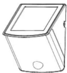
- Light fixture (A)
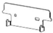
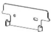
- Mounting plate (B)
• (2) Fixture mounting screws (C)
• (2) Plastic Plugs (D)
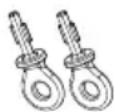
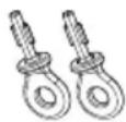
• (2) Keys (E)
• (1) Key chain (F)
• (3) “AA” Ni-MH rechargeable batteries (installed)
natural_image
Line drawing of a rectangular container with a square lid and circular base (no text or symbols)A
B

C

D
E
F
WHAT TO KNOW
PLEASE READ THESE IMPORTANT SAFETY INSTRUCTIONS
- To Reduce Risk of Fire or Injury to Persons, Read and Follow these Instructions:
- For outdoor use only.
- Use only the following type and size batteries: “AA” Ni-MH rechargeable batteries. Make sure that replacement batteries are the same size as current batteries.
- Do not operate the luminaire fitting with a missing or damaged shield.
- Do not dispose of the battery in a fire. The cell may explode. Check with local codes for possible special disposal instructions.
- Do not open or mutilate the battery. Released electrolyte is corrosive and may cause damage to the eyes or skin. It may be toxic if swallowed.
- Exercise care in handling the batteries in order not to short the battery with conducting materials such as rings, bracelets and keys. The battery or conductor may overheat and cause burns.
Call for customer service and/or missing or damaged parts (800-334-6871)
- Charge the battery provided with or identified for use with this product only in accordance with the instructions and limitations specified in this manual.
- Observe proper polarity orientation between the batteries and battery charger/compartment.
- Disassembly of your fixture will void the warranty.
- Fixture is suitable for wall mount only. NOT suitable for ground mount installation.
SAVE THESE INSTRUCTIONS
FOR BEST RESULTS
- Locate solar panel in an area that will receive the maximum amount of sunlight during the daylight hours.
- Allow fixture to receive four full days of sunlight before turning fixture ON.
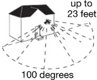
• Install your fixture 6-8 feet above ground (motion detector is less sensitive above 8 feet).
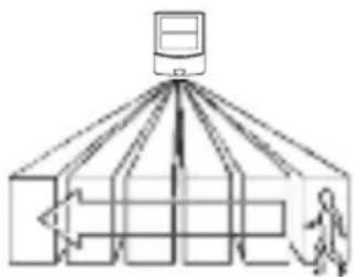
- Locate fixture so motion moves across detection zone (Fig. 1).
- Locate fixture away from heat producing sources to prevent false triggering. Also be very careful not to include objects such as windows, white walls, barbecues, air conditioners, flue vents, and water in the detection zone whenever possible.
- Locate fixture away from moving objects such as trees and street traffic.
- Do not aim the sensor at reflective surfaces such as smooth white walls, swimming pools, etc.
- Keep solar panel clear of any objects that will block the sunlight. It will be necessary to periodically clean the solar panel with soft wet cloth.
- During periods of several cloudy days, the battery will become discharged and will need to be recharged with sunlight.
- After receiving full charge, fixture ON capacity is up to 3 hours.
flowchart
graph TD
    A["Central Server"] --> B["Data Processing Unit 1"]
    A --> C["Data Processing Unit 2"]
    A --> D["Data Processing Unit 3"]
    A --> E["Data Processing Unit 4"]
    A --> F["Data Processing Unit 5"]
    A --> G["Data Processing Unit 6"]
    A --> H["Data Processing Unit 7"]
    A --> I["Data Processing Unit 8"]
    A --> J["Data Processing Unit 9"]
    A --> K["Data Processing Unit 10"]
Fig. 1
Note: All PIR sensors in cold/dry environments are more sensitive than those in hot/wet environments.
HOW TO REPLACE BATTERIES
Note: Use only the following type and size batteries: "AA" Ni-MH rechargeable batteries. Make sure that replacement batteries are the same dimension as current batteries.
- Unlock fixture from mounting plate by inserting the key (supplied) in the lock on the side of the fixture. Rotate key to the OPEN position. Remove the fixture from the wall by lifting up on the bottom of the fixture. Support the fixture securely with both hands.
- Rotate the fixture so that you are looking at the back mounting surface of the fixture. Move the switch to the OFF position.
- Make sure that the switch is in the OFF position before you proceed. Remove the four (4) screws from the battery cover to expose the batteries.
Call for customer service and/or missing or damaged parts (800-334-6871)
- Remove the old batteries by hand. Insert new batteries making sure that you observe the proper polarity orientation between batteries and battery charger/holder.
- Replace the battery cover making sure that the rubber gasket in the grove of the battery cover is still in place and that no wires have been pinched.
- Do NOT move switch to the ON position until batteries are fully charged. Allow solar panel to receive four (4) full days of sunlight with the switch in the OFF position before turning fixture ON, or in AUTO mode.
- Hang the fixture back on the mounting plate and rotate key to the locked position for the charging period.
INSTALLATION INSTRUCTIONS
Note: Your fixture is supplied with a pre-installed long life (non replaceable) LED bulbs.
- Locate area in which you would like to install your light fixture.
Note: For fixture to operate properly, the solar panel must be located in an area that will receive the maximum amount of sunlight and is free from obstructions.
-
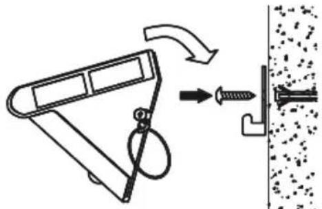
Drill two holes on wall where you want the light to be mounted on and put the plastic plugs into the holes. Then attach the mounting plate with the mounting screws (Fig. 2).
-
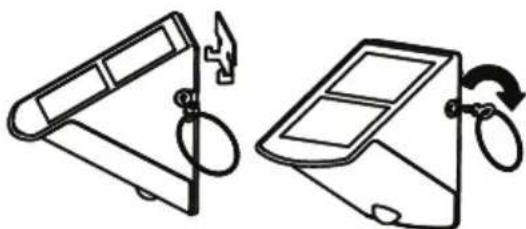
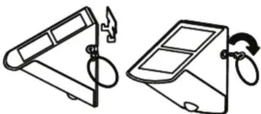
Hang the light on the mounting plate and lock it by turning the key. Remove the key and keep it for future use (Fig. 3).
-
Allow fixture to receive four full days of sunlight before turning fixture to the ON position.
natural_image
Diagram showing a mechanical device with a spring and screw, connected to a textured surface (no text or symbols)Fig. 2
natural_image
Two line drawings of a portable device with a handle and scroll, showing mechanical components (no text or symbols)Fig. 3
HOW TO OPERATE YOUR FIXTURE
- After fixture has received four (4) full days of sunlight, turn the switch on the back of the fixture to the AUTO position.
-
Mount the light in a place where it can receive the maximum DIRECT SUNLIGHT in the daytime. The inside batteries are charged by a solar cell. The more direct sun light the solar cell received in the daytime, the longer the light will run. It is better to charge the solar cell in the sunlight for up to 4 days before switching it ON, so that the light can work with a full charge.
-
Modes of slide switch (Fig. 4):
AUTO: Normal working mode
ON: Light is constantly on as an emergency lamp.
Note: Do not leave in this position. Always return switch to the AUTO, or OFF position. If light has been ON for more than 2 hours, turn the switch to OFF and let the batteries recharge.
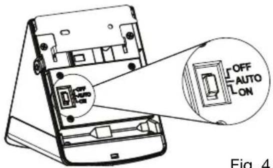
Fig. 4
OFF: Power is off for storage and long time charging.
Note: When the light is turned on for the first time, the LED light and the PIR will start warming up. Then the LEDs will stay on for 40 seconds, flash 3 times and shift to the detection mode. At night, the LEDs will stay on for 60 seconds after the last movement was detected. If a movement is detected while the light is already on, the duration time will be renewed and the LEDs will remain on another 60 seconds. In the daylight or a bright environment, the light will not activate.
WHAT TO DO IF
| LIGHT DOES NOT COME ON WITH MOTION AT NIGHT | Is the surrounding external ambient light too bright? (If so, the unit may think it's daytime.)·Redirect the sensor or PIR·Relocate or reposition the unit away from the light.Is the fixture being charged during the day?·Solar panel must be receiving sunlight to charge during day (reposition if shadowed).·Solar panel must be clean and free from debris.·Check batteries, replace if necessary·Make sure batteries have been charged for 4 full days of sunlight prior to turning the fixture on. |
| LIGHT COMES ON FOR NO APPARENT REASON AT NIGHT OR LIGHT STAYS ON AT NIGHT AND DOES NOT TURN OFF | Is there motion in the detection zone?·Make sure the sensor is not picking up moving objects such as trees, traffic, etc.TEST FOR YOURSELF·Cover the sensor lens with cardboard to prevent sensor from detecting motion. If the lights stay off, something in the detection zone is triggering the sensor.·Reposition or redirect lens of the PIR sensor*If the lights stay on with sensor lens covered, or lights continue to stay on, contact customer service. |
| LIGHT IS ON DURING THE DAY | Is the lens of the PIR sensor detector shadowed?·Reposition motion sensor. |
Cooper Lighting, LLC (“the Company”) warrants this product (“the product”) against defects in material or workmanship for a period of one year from date of original purchase, and agrees to repair or, at the Company’s option, replace a defective product without charge for either replacement parts or labor during such time. This does not include labor to remove or install fixtures.
This warranty is extended only to the original purchaser of the product.
A purchasers receipt or other proof of date of original purchase acceptable to the Company is required before warranty performance shall be rendered.
This warranty only covers product failure due to defects in materials or workmanship which occurs in normal use. It does not cover the bulb or failure of the product caused by accident, misuse, abuse, lack of reasonable care, alteration, or faulty installation, subjecting the product to any but the specified electrical service or any other failure not resulting from defects in materials or workmanship.
There are no express warranties except as described above.
THE COMPANY SHALL NOT BE LIABLE FOR INCIDENTAL, SPECIAL OR CONSEQUENTIAL DAMAGES RESULTING FROM THE USE OF THE PRODUCT OR ARISING OUT OF ANY BREACH OF THIS WARRANTY. ALL IMPLIED WARRANTIES, IF ANY, INCLUDING IMPLIED WARRANTIES OF MERCHANTABILITY AND FITNESS FOR A PARTICULAR PURPOSE, ARE LIMITED IN DURATION TO THE DURATION OF THIS EXPRESS WARRANTY.
Some states do not allow the exclusion or limitation of incidental or consequential damages, or limitations on how long an implied warranty lasts, so the above exclusions or limitations may not apply to you.
No other warranty, written or verbal, is authorized by the Company. This warranty gives you specific legal rights, and you may also have other rights which vary from state to state.
To obtain warranty service, please contact Cooper Lighting, LLC, call 1-800-334-6871, press option 2 for Customer Service, or via e-mail parts@cooperlighting.com. All returned products must be accompanied by a Return Goods Authorization Number issued by the Company and must be returned freight prepaid.
Any product received without a Return Goods Authorization Number from the Company will be refused.
Cooper Lighting, LLC is not responsible for merchandise damaged in transit. Repaired or replaced products shall be subject to the terms of this warranty and are inspected when packed. Evident or concealed damage that is made in transit should be reported at once to the carrier making the delivery and a claim filed with them.
COOPER Lighting
Customer First Center 1121 Highway 74 South, Peachtree City, GA 30269 www.cooperlighting.com
© 2009 Cooper Lighting, LLC
Reproductions of this document without prior written approval of Cooper Lighting, LLC are strictly prohibited.
Call for customer service and/or missing or damaged parts (800-334-6871)
Printed in China
natural_image
Line drawing of a rectangular container with a square lid and a circular hole, labeled A (no text or symbols on the diagram itself)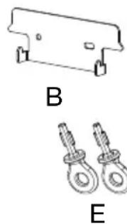
natural_image
Technical line drawing of a bracket and two hanging fasteners labeled B and E (no text or symbols on the components)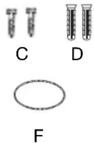
natural_image
Three labeled test tubes (C, D, F) with different shapes, no text or symbols presentQUÉ DEBE SABER
natural_image
Diagram showing a mechanical device with a spring attached to a wall, illustrating the process of lifting or fastening (no text or symbols present)Fig. 2
natural_image
Two line drawings of a portable device with a handle and scroll, showing mechanical components (no text or symbols)Fig. 3
Customer First Center 1121 Highway 74 South, Peachtree City, GA 30269 www.cooperlighting.com
© 2009 Cooper Lighting, LLC
natural_image
Line drawing of a rectangular container with a square lid and a small circular hole at the bottom (no text or symbols)A
B

C

D
E
F
CE QU'IL FAUT CONNAÎTE
VEUILLEZ LIRE CES IMPORTANTES INSTRUCTIONS DE SÉCURITÉ
natural_image
Two diagrams showing a device with a handle and a switch, labeled 'Sch. 3' (no text or symbols on the devices themselves)Customer First Center 1121 Highway 74 South, Peachtree City, GA 30269 www.cooperlighting.com
© 2009 Cooper Lighting, LLC