MSL180W - Lamp Cooper Lighting - Free user manual and instructions
Find the device manual for free MSL180W Cooper Lighting in PDF.

User questions about MSL180W Cooper Lighting
0 question about this device. Answer the ones you know or ask your own.
Ask a new question about this device
Download the instructions for your Lamp in PDF format for free! Find your manual MSL180W - Cooper Lighting and take your electronic device back in hand. On this page are published all the documents necessary for the use of your device. MSL180W by Cooper Lighting.
USER MANUAL MSL180W Cooper Lighting
natural_image
Line drawing of two electronic devices: a solar panel and a camera with a circular lens (no text or symbols)MSL180 MSL180W
Instruction Manual Instrucciones Directives
Congratulations. You have purchased a motion activated solar floodlight.
This light is constructed of durable plastic and will provide years of trouble free and weatherproof service.
HOW IT WORKS
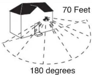
During the daylight hours, the solar panel turns the sunlight into energy that is stored in the rechargeable battery. Your light features a motion sensor that turns the light ON at night when motion is detected. This light is equipped with a photocell, which only allows the fixture to turn ON during the nighttime hours.
WHAT YOU NEED
• Phillips screwdriver
- Flat head screwdriver
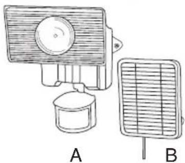
WHAT'S INCLUDED
- Light fixture (A)
- Solar Panel (B)
• 15 Watt, 6 Volt G4 bi-pin Halogen bulb (C)
• (5) Mounting Screws (D)
natural_image
Illustration of two household appliances: a front-mounted device and a front-mounted grid fan (no text or symbols)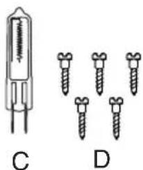
natural_image
Diagram showing two types of dental implants: a cylindrical device labeled C and four screws labeled D (no text or symbols present)WHAT TO KNOW
PLEASE READ THESE IMPORTANT SAFETY INSTRUCTIONS INSTRUCTIONS PERTAINING TO A RISK OF FIRE OR INJURY TO PERSONS:
Lighted lamp is HOT!
To Reduce Risk of Fires or Injury to Persons, Read and Follow these Instructions:
- For outdoor use only.
- Turn off and allow to cool before replacing bulb.
- Bulb gets HOT quickly! Contact switch only when turning on.
- Do not touch hot lens, guard, or enclosure.
- Keep away from flammable objects. Do not position fixture within one inch of any combustible materials.
- Never touch the bulb with your bare hands, as oil from your skin can cause premature failure. Always handle the bulb with gloves or a soft cloth.
- Do not operate the luminaire fitting with a missing or damaged shield.

- Fixture is suitable for wall mount only. NOT suitable for ground mount installation.
- Use only the following type and size batteries: Sealed Lead Acid 6 volt battery. Make sure that replacement battery is same size as current battery. Replacement batteries are available at most hardware home center stores.
- Do not dispose of the battery in a fire. The cell may explode. Check with local codes for possible special disposal instructions.
- Do not open or mutilate the battery. Released electrolyte is corrosive and may cause damage to the eyes or skin. It may be toxic if swallowed.
- Exercise care in handling the batteries in order not to short the battery with conducting materials such as rings, bracelets and keys. The battery or conductor may overheat and cause burns.
- Charge the battery provided with or identified for use with this product only in accordance with the instructions and limitations specified in this manual.
- Observe proper polarity orientation between the batteries and battery charger/compartment.
- Disassembly of your fixture will void the warranty.
- Do not cut the solar panel wire. Discontinue use if the wire becomes frayed or broken.
SAVE THESE INSTRUCTIONS.
FOR BEST RESULTS
- Locate solar panel in an area that will receive the maximum amount of sunlight during the daylight hours.
- Allow fixture to receive four full days of sunlight before turning fixture ON.
- Install your fixture 8-12 feet above ground (motion detector is less sensitive above 12 feet.
- Locate fixture so motion moves across detection zone (Fig. 1).
- Locate fixture away from heat producing sources to prevent false triggering. Also be very careful not to include objects such as windows, white walls and water in the detection zone whenever possible.
- Locate fixture away from moving objects such as trees and street traffic.
- You will need to adjust the angle of the solar panel throughout the year as seasons change in order to keep it at the best possible angle to the sun.
- Keep solar panel clear of any objects that will block the sunlight. It will be necessary to periodically clean the solar panel with soft wet cloth.
- During periods of several cloudy days, the battery will become discharged and will need to be recharged with sunlight.
Note: When battery is low, light may cycle on and off repeatedly. Turn off fixture until fully recharged.
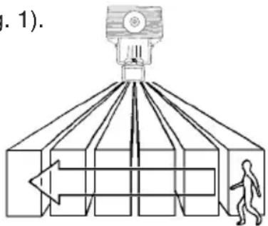
Fig. 1
Note: Disconnect power and allow fixture to cool before removing burned-out bulbs.
Note: Your fixture is supplied with a 15 Watt, 6 Volt G4 bi-pin halogen bulb. Always replace with the same or lower wattage bulb. Replacing with a higher wattage bulb will reduce battery life.
Note: Never touch bulb with bare hands as oil from your skin can cause premature failure (Fig. 2).

Fig. 2
CAUTION: When replacing bulb in fixture, always replace with the same wattage bulb or a lower wattage bulb. DO NOT replace with a bulb of greater wattage than specified on the fixture. To do so could create a fire hazard and / or shorten the life of the bulb.
-
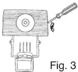
Before replacing bulb, turn fixture to the OFF position.
-
Insert flat head screwdriver in slot at end of lamp compartment and carefully pry lens out (Fig. 3).
-
Bulb will be extremely hot if touched while bulb is burning or immediately after bulb is off.
-
Allow bulb to cool before touching. DO NOT touch bulb with bare hands.
-
Grasp bulb and gently pull out of socket.
-
Replace bulb by lining up the pins of the bulb to the holes in the socket and gently pressing down.
-
Replace lens by lining up the notches at the bottom of the lens with the notches on the bottom of the lamp compartment and then gently pressing in at the top until it snaps into place.
-
Turn fixture back to the ON position.
natural_image
Line drawing of a mechanical device with a lever and base, labeled Fig. 3 (no text or symbols on the device itself)INSTALLATION INSTRUCTIONS
Note: Your fixture is supplied with a 15 watt halogen bulb, which is shipped in the lamp compartment of the fixture. The lamp must be installed before use. Please see "Installing or Replacing the Bulbs"
section of the instruction sheet for installation instructions.
- Locate area in which you would like to install your light fixture.
Note: For fixture to operate properly, the solar panel must be located in an area that will receive the maximum amount of sunlight and is free from obstructions.
-
Using two of the mounting screws provided, mount fixture to a solid surface 8-12 feet above the ground, by placing the screws through the holes on either side of the fixture (Fig. 4). Adjust sensor head so that control switches are facing the ground. Remove label from the front of the sensor head.
-
Using three of the mounting screws provided, mount solar panel to a solid surface (Fig. 5). Adjust the angle of the solar panel so that it will receive the maximum amount of direct sunlight possible during the daylight hours.
Fig. 4
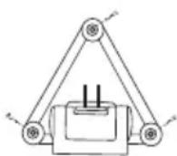
Fig. 5
The solar panel can be mounted up to 16 feet away from the light fixture.
-
Carefully route the wire from the solar panel to the fixture and plug it into the connector extending from the bottom of the fixture housing. (For now, keep fixture in the OFF position) (Fig. 6).
-
Allow fixture to receive four full days of sunlight before turning fixture to the ON position.
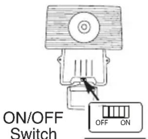
Fig. 6
HOW TO OPERATE YOUR FIXTURE
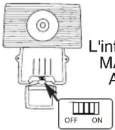
- After fixture has received four full days of, sunlight, slide the ON/OFF switch on the bottom of the housing to the ON position (Fig. 6).
Note: Fixture has a warm up period of about one minute. Light may turn on during this period. Once the light turns off, you are ready to test.
- Move slide switch on the bottom of the sensor to "TEST". Set sensitivity knob to medium (halfway) (Fig. 7).
- Aim sensor toward the general direction that motion will be coming from. Maintain at least 1" of clearance between sensor head and lamps. Always position the sensor head with control switches facing toward the ground.
- Walk through the detection zone at the farthest distance you want your detector to detect motion.
- Adjust the SENSITIVITY knob until you get desired results. For more range, aim sensor slightly upward. For less range, aim sensor head slightly downward. Lights will turn off 4 seconds after motion stops.
Note: Allow five seconds after light turns off before your next test.
- Move slide switch to "AUTO". Light will turn on at night when motion is detected and turn off 30 seconds after motion stops.
This is the bottom side of the motion detector
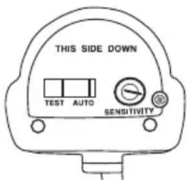
Fig. 7
PROPER BATTERY CARE
Note: Under normal conditions, the included battery should work for two years. Proper care should ensure the longest possible life for your battery.
- Make sure that your solar panel is located in a sunny location.
- Allow the solar panel to collect sunlight (charge the battery) for four days before switching the fixture ON.
-
Any of the following behaviors are an indication of low charge on your battery. Switch the fixture OFF and allow the battery four sunny days to recharge the battery before turning the fixture back ON. A series of cloudy days may drain your battery. Proper recharging will prolong battery life.
-
When motion is detected (in AUTO mode), fixture turns on but then off after 1-3 seconds.
- When motion is detected (in AUTO mode), fixture turns on but then flashes periodically.
- When the length of the lighting time (30 seconds) becomes noticeably shorter.
- When the fixture's brightness is noticeably dimmer.
Note: Use only the following type and size battery: Sealed Rechargeable Lead Acid 6 Volt 4 ampere hour battery. Make sure that replacement battery is same size (2-3/4" x 3-7/8" x 1-13/16") as the current battery.
- Turn the fixture to the OFF position and unplug the solar panel from the connector extending from the bottom of the fixture housing.
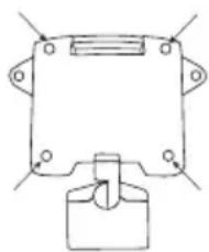
- Remove fixture from it's mounting surface by removing the two screws on each side of the fixture. Remove the four screws on the back (Fig. 8).
- Carefully turn the fixture over and lay it on its back. Slowly lift the front cover to the side making sure that you do not stress the wiring.
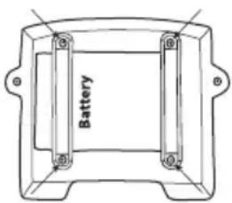
- Locate the two brackets that hold the battery into place and remove the four screws (Fig. 9).
- Lift battery and unplug the positive and negative leads. Attach the leads from the fixture to the terminals of the new battery, making sure to connect the positive lead to the positive terminal and the negative lead to the negative terminal.
- Place the battery into the fixture and replace the two brackets that hold the battery in place, make sure that none of the wiring is trapped under the brackets before installing any of the screws.
- Carefully replace fixture cover, making sure to properly seat the groove of the top cover into the channel of the bottom cover and that none of the wiring has been pinched.
- Replace the four screws in the back of the fixture.
- Mount fixture back to the mounting surface and plug in solar panel.
- Allow fixture to receive four full days of sunlight before turning fixture ON.
natural_image
Pure mechanical component diagram without any text, numbers, or symbolsFig. 8
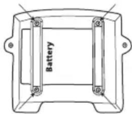
Fig. 9
| FLOODLIGHT DOES NOTCOME ON WITH MOTION ATNIGHT | Is the surrounding external ambient light too bright? (If so, the unit may think it's daytime.)• Re-aim the head.• Relocate or reposition the unit away from the light.Is the fixture being charged during the day?• Solar panel must be connected to the connector extending from the bottom of the fixture housing when charging.• Solar panel must be receiving sunlight to charge during day (reposition if shadowed).• Solar panel must be clean and free from debris.• Check batteries, replace if necessary* Make sure batteries have been charged for 4 full days of sunlight prior to turning the fixture on. |
| FLOODLIGHT COMES ON FORNO APPARENT REASON ATNIGHT | Is there motion in the detection zone?• Make sure the sensor is not picking up moving objects such as trees, traffic, etc.TEST FOR YOURSELF• Cover the sensor lens with cardboard to prevent sensor from detecting motion. If the lights stay off, something in the detection zone is triggering the sensor.• If this is the case, reduce the sensitivity.• Reposition motion sensor.*If the lights stay on with sensor lens covered, contact customer service. |
| FLOODLIGHT STAYS ON ATNIGHT AND DOES NOT TURNOFF | Is there motion in the detection zone?• Make sure the sensor is not picking up moving objects such as trees, traffic, etc.• If this is the case, reduce the sensitivity.• Reposition motion sensor.*If the lights continue to stay on, contact customer service. |
| FLOODLIGHT IS ONDURING THE DAY | Is the switch on the bottom of the motion sensor in the TEST mode?• Move the switch to the AUTO position.Is the motion detector shadowed?• Reposition motion sensor. |
Cooper Lighting, LLC (“the Company”) warrants this product (“the product”) against defects in material or workmanship for a period of two years from date of original purchase, and agrees to repair or, at the Company’s option, replace a defective product without charge for either replacement parts or labor during such time. This does not include labor to remove or install fixtures.
This warranty is extended only to the original purchaser of the product. A purchasers receipt or other proof of date of original purchase acceptable to the Company is required before warranty performance shall be rendered.
This warranty only covers product failure due to defects in materials or workmanship which occurs in normal use. It does not cover the bulb or failure of the product caused by accident, misuse, abuse, lack of reasonable care, alteration, or faulty installation, subjecting the product to any but the specified electrical service or any other failure not resulting from defects in materials or workmanship.
There are no express warranties except as described above. THE COMPANY SHALL NOT BE LIABLE FOR INCIDENTAL, SPECIAL OR CONSEQUENTIAL DAMAGES RESULTING FROM THE USE OF THE PRODUCT OR ARISING OUT OF ANY BREACH OF THIS WARRANTY. ALL IMPLIED WARRANTIES, IF ANY, INCLUDING IMPLIED WARRANTIES OF MERCHANTABILITY AND FITNESS FOR A PARTICULAR PURPOSE, ARE LIMITED IN DURATION TO THE DURATION OF THIS EXPRESS WARRANTY.
Some states do not allow the exclusion or limitation of incidental or consequential damages, or limitations on how long an implied warranty lasts, so the above exclusions or limitations may not apply to you.
No other warranty, written or verbal, is authorized by the Company. This warranty gives you specific legal rights, and you may also have other rights which vary from state to state.
To obtain warranty service, please write to Cooper Lighting, LLC, 1121 Highway 74 South, Peachtree City, GA 30269. Enclose product model number and problems you are experiencing, along with your address and telephone number. You will then be contacted with a solution, or a Return Goods Authorization number and full instructions for returning the product. All returned products must be accompanied by a Return Goods Authorization Number issued by the Company and must be returned freight prepaid. Any product received without a Return Goods Authorization Number from the Company will be refused.
Cooper Lighting, LLC is not responsible for merchandise damaged in transit. Repaired or replaced products shall be subject to the terms of this warranty and are inspected when packed. Evident or concealed damage that is made in transit should be reported at once to the carrier making the delivery and a claim filed with them.
COOPER Lighting
Customer First Center 1121 Highway 74 South, Peachtree City, GA 30269
www.cooperlighting.com
This product may be covered by one or more of the following patents
and additional patents pending:
D428,352
© 2009 Cooper Lighting, LLC
Reproductions of this document without prior written approval of Cooper Lighting, LLC are strictly prohibited.
Printed in China
QUÉ SE REQUIERE
• Destornillador Phillips
- Destornillador Plano
QUÉ SE INCLUYE
natural_image
Line drawing of a portable air conditioner unit (A) and its corresponding grid-mounted device (B), both without any text or symbols.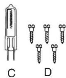
natural_image
Diagram showing a cylindrical device and four screw-like components labeled C and D (no text or symbols present)natural_image
Line drawing of a mechanical device with a handle and base (no text or symbols)Fig. 3
natural_image
Simple line drawing of a mechanical device with no text or symbolsFig. 4
natural_image
Pure mechanical diagram showing a bracket with mounting holes and a central knob (no text or symbols)Fig. 8
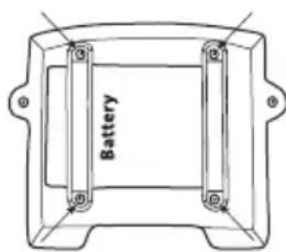
Fig. 9
Customer First Center
1121 Highway 74 South, Peachtree City, GA 30269
www.cooperlighting.com
© 2009 Cooper Lighting, LLC.
natural_image
Illustration of four different types of electrical sensors and screw packages (no text or symbols present)CE QU'IL FAUT CONNAÎTRE
VEUILLEZ LIRE CES IMPORTANTES INSTRUCTIONS DE SÉCURITÉ. INSTRUCTIONS RELATIVES AU RISQUE D'INCENDIE OU DE BLESSURES :
natural_image
Diagram of a mechanical or optical setup with a central device and a human figure inside a chamber, no text or symbols present.Sch. 1
COMMENT REMPLACER L'AMPOULE
natural_image
Line drawing of a hand holding a pen (no text or symbols)Sch. 2
natural_image
Line drawing of a vintage mechanical device with a handle and base, labeled 'Sch. 3' (no other text or symbols)INSTRUCTIONS D'INSTALLATION
natural_image
Simple line drawing of a triangular frame with a central component and two side connectors (no text or symbols)Sch. 5
natural_image
Pure mechanical component diagram without any text, numbers, or symbolsSch. 8
Sch. 9
Customer First Center 1121 Highway 74 South, Peachtree City, GA 30269 www.cooperlighting.com
© 2009 Cooper Lighting, LLC