AC-THOR - Boiler My-PV - Free user manual and instructions
Find the device manual for free AC-THOR My-PV in PDF.

User questions about AC-THOR My-PV
0 question about this device. Answer the ones you know or ask your own.
Ask a new question about this device
Download the instructions for your Boiler in PDF format for free! Find your manual AC-THOR - My-PV and take your electronic device back in hand. On this page are published all the documents necessary for the use of your device. AC-THOR by My-PV.
USER MANUAL AC-THOR My-PV
natural_image
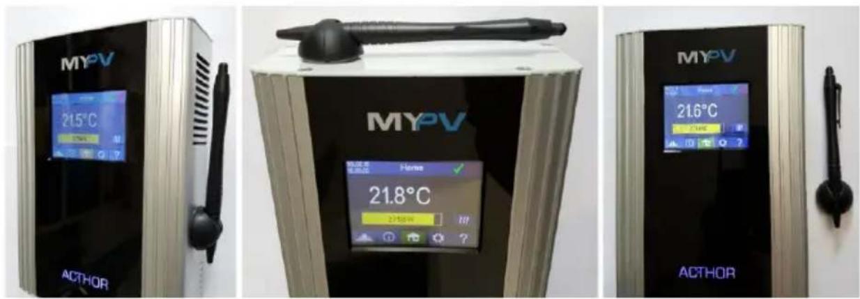
Exterior view of a modern industrial control unit (no visible text or symbols on the device body)AC•THOR®
Montageanleitung
Assembly Instructions
In addition to these assembly instructions, the current version of the Operating instructions for the device is available at www.my-pv.com.
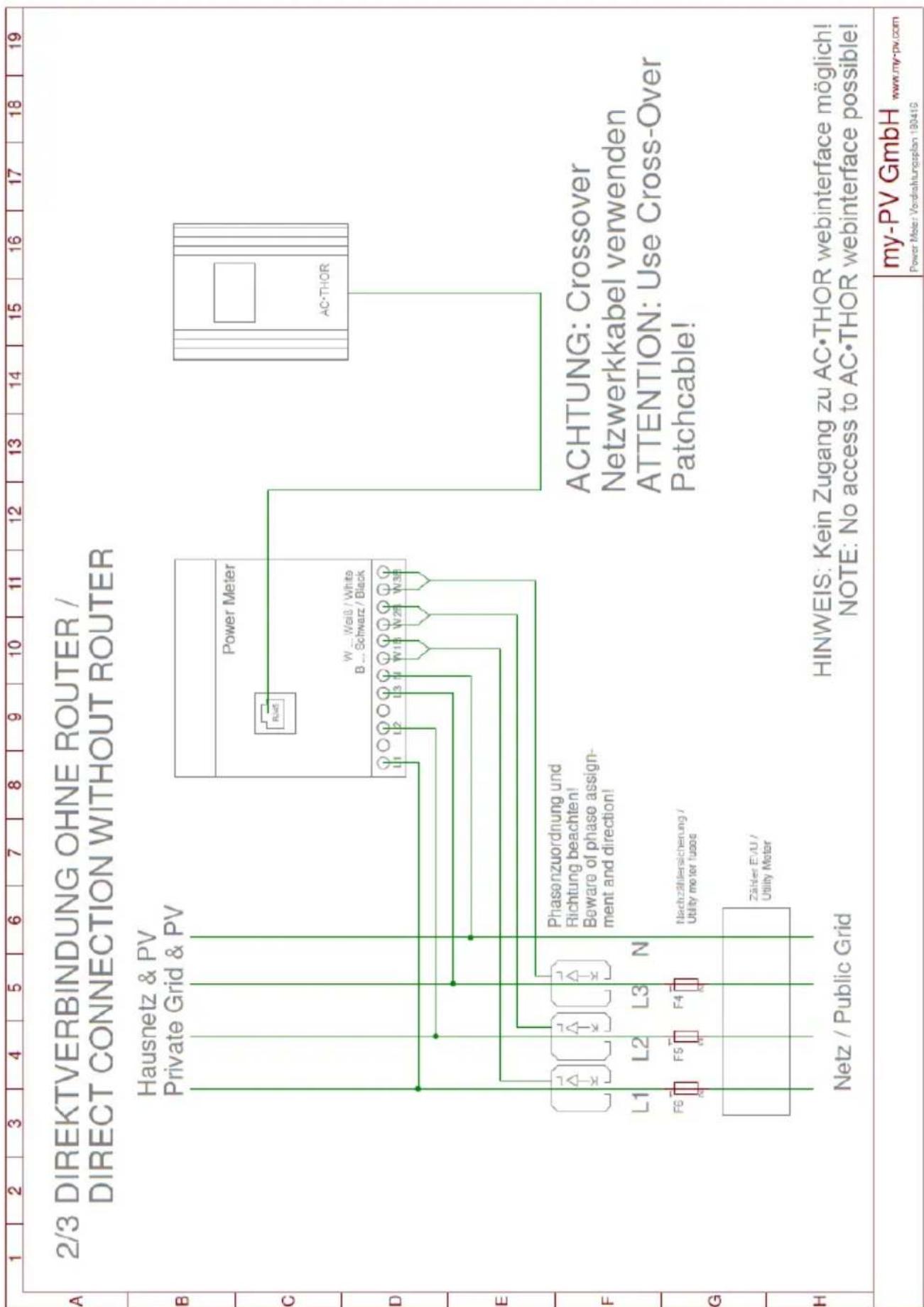
Wiring diagrams at the end of the document.
The following device key is required for online registration of the unit. Keep it safe! It may be necessary to update the firmware for operation. The procedure is explained in the above-mentioned operation manual.

natural_image
Close-up of a computer motherboard with ventilation slots and connectors (no visible text or symbols)natural_image
Exterior view of a modern office building (no signage)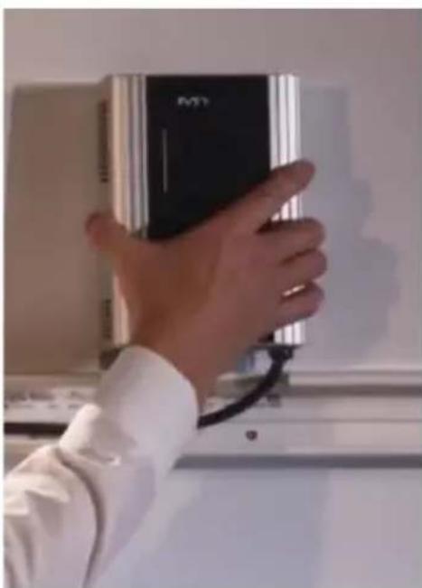
natural_image
Hand holding a black and silver electronic device against a white wall (no visible text or symbols)Photovoltaic-Power-Manager for hot water and space heating
Assembly Instructions English
Content
Content 12
Intended use ....13
Scope of supply....13
Safety instructions....13
Limitation of warranty and liability 14
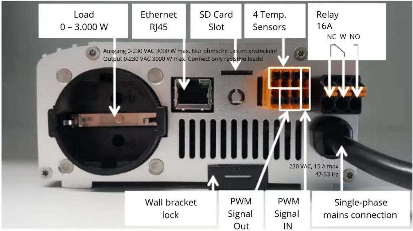
Connections....15
Modbus RTU connection for external control 15
Assembly....16
Connecting several temperature probes ....17
Electrical connection ....18
Electrical connection for multiple units 18
Maintenance....18
Operation displays....19
Troubleshooting....19
Disposal 19
EU declaration of conformity....19
Technical specifications....20
Intended use
The electronic AC•THOR Photovoltaic-Power-Manager (in the following, AC•THOR for short) is designed for operating resistive loads such as electric immersion heater elements, electric boilers, electric convectors, electric heating mats or infrared panels.
The unit controls the output voltage according to external signals (temperatures, Ethernet- and other control signals) linearly and thus the power output of the connected load.
The AC•THOR is controlled by the my-PV Power Meter or can be combined with products of different manufacturers (the current list of manufacturers can be seen under www.my-pv.com).
The AC•THOR is designed for fixed installations indoors.

Installation in rooms with a high level of humidity must comply with relevant regulations!
Any application other than those described above may cause damage.
Furthermore, this may lead to hazards such as a short circuit, fire, electric shock, etc. The safety instructions and the information on handling in this manual and in the operation instructions shall be followed!
The product complies with the statutory, national and European requirements. The names of the company and products are trademarks of my-PV GmbH. All rights reserved.

You will find a comprehensive description of the unit's functions and potential settings using the display or via web interface in the online Operating instructions.
Scope of supply
• AC•THOR Electronic Photovoltaic Power Manager
• Wall bracket (on the rear of the unit)
- Assembly set (3 screws 4.2 x 32 mm, 3 wall-plugs 6 mm)
• my-PV digital temperature sensor (cable length 5 m) with 8-pin plug
- Plug, 3-pin for 16 A switch output (attached to the unit)
- Operator stylus for the display with holder
- Assembly Instructions
• Key-fob AC•THOR

Safety instructions
The AC•THOR is designed for fixed installations indoors.
The connected units may only be pure resistive electric loads such as immersion heater elements, boilers, convectors, heating mats or infrared panels! The units connected must be suitable for variable supply voltages between 0-230 V AC (in no circumstances units with electronic power supply) as this otherwise may cause damage to the AC•THOR or to the other loads connected to it.
Only connect loads fitted with suitable mains plugs to the load socket!
In cases where the load to be connected has no mains plug, a 16 A earthed EURO mains plug must be fitted (not supplied).
Operation of heating systems incorporating electronic thermostats is not possible!
For heating water, only heaters with an integral safety temperature limiter may be connected.
Installation must be carried out by an accredited specialist.
Comply with the relevant standards when mounting and connecting the device.
The unit housing may heat up during operation. Only mount the unit on non-combustible surfaces.
The unit is only intended for use in dry rooms indoors. Otherwise there is a risk of fatal electric shock!

Installation in rooms with a high level of humidity must comply with relevant regulations!
Do not install the device in an environment contaminated with ammonia.
Do not install the device in a dusty environment.
The ventilation holes of the housing must not be covered.
Avoid exposure to high temperatures ( >40^ ), low temperatures ( <5^ ) or direct sunlight during storage and operation.
The AC•THOR must be connected to a nominal voltage of 230 V AC, 50/60 Hz.
Protection of the mains connection for the AC•THOR may not exceed 16 A (tripping characteristic B or C).
The accident prevention regulations established by the German Employer's Liability Insurance Association for electrical equipment and facilities must be adhered to in commercial facilities.
This unit can be used by children ages 8 and persons with reduced physical, sensory or mental capabilities or lack of experience and knowledge if they have been given supervision or instruction concerning the safe use of the equipment and understand the resulting risks.
Children should not play with the appliance. Cleaning and user maintenance shall not be undertaken by children without supervision.
Limitation of warranty and liability
A limitation of warranty and liability applies for:
- any damage or injury caused by improper handling or failure to observe the assembly and operating instructions
- Consequential damage, in particular to the connected loads
- Altering, disassembling or otherwise intervening in the device or making changes to the device without authorisation
Connections
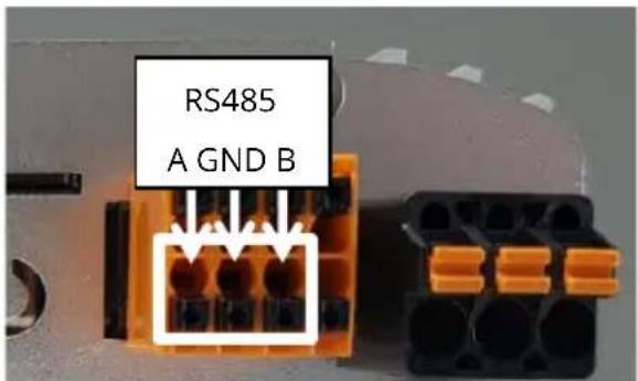
Modbus RTU connection for external control

Use shielded twisted pair wire!

RTU bus must be equipped with a 120 Ohm termination resistor!
(Not included in the scope of delivery)

When controlling via Modbus RTU, the operating mode M7 cannot be used!
Assembly

A brief video (German) to explain assembly will also be found online: https://www.youtube.com/watch?v=WFHbayf5VDQ

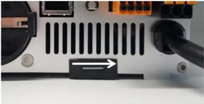
Remove the wall bracket from the rear of the AC•THOR unit. To do this, slide the lock underneath to the right.
natural_image
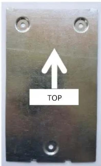
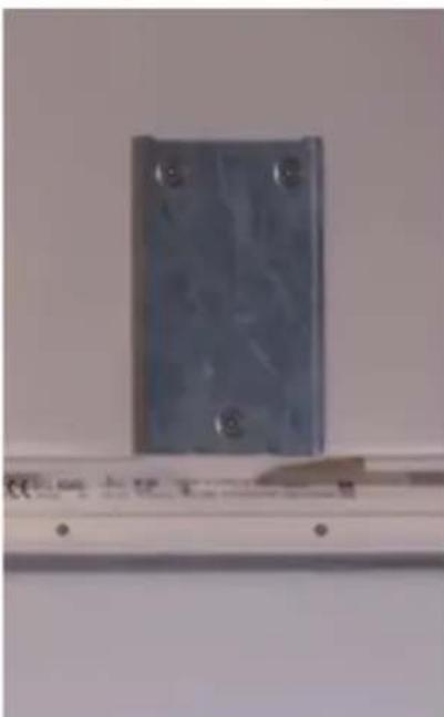
Close-up of a computer motherboard with ventilation slots and connectors (no visible text or symbols)Then fix the wall bracket to the wall with three screws. Three screws and three wall-plugs are supplied. If the screws supplied are not suitable for the substrate, suitable screw must be obtained.
natural_image
Exterior view of a modern office building (no signage)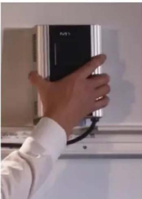
natural_image
Hand holding a black M1 device against a wall, no visible text or symbols on the device itselfTo fix it to the wall bracket, the AC•THOR is suspended in the wall bracket by the two long slots on top and then fixed in place by locking it underneath (slide to the left).

Check the AC•THOR is securely fixed!
When installing in an electrical cabinet, ensure sufficient cooling, for example through ventilation slots in the switch cabinet door!
A minimum lateral distance of 7cm must be observed!
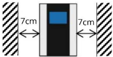
When installing several devices side by side, a minimum distance of 10cm must be observed!

Then the electrical connections can be made.
Do not immerse my-PV temperature sensor(s) directly in water. Use a thermowell!

TIP: For mains leads, use a cable duct with a depth of 60 mm. The necessary cut-out measures 130 x 60 mm.
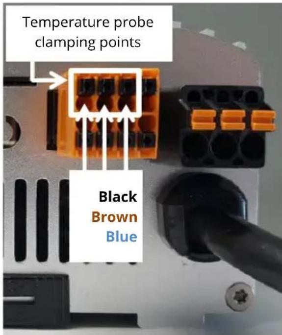
Connecting several temperature probes
Up to four digital temperature probes (three-core, bus system) can be connected to the AC•THOR. The terminal positions for the three cores are shown in the following illustration.

TIP: If more than one probe is used, the cores can also be connected externally in parallel!

Electrical connection
Protection of the mains connection for the AC•THOR may not exceed 16 A (tripping characteristic B or C).

The PE conductor of the socket must be connected!
Pay attention to other loads on the line circuit, this may trip the circuit breaker!
The conductor cross-sections at the mains connection and at the load connections must be at least 1.5 mm^2 .

Electrical connection for multiple units
All devices should be connected to appropriate AC circuits. Note that each AC•THOR takes up to 3 kW power (with relay output up to 6 kW). It makes sense to divide this between the phases on the grid.
Maintenance
Do not attempt to open the unit. The device does not contain any parts that may be repaired by the user.

Never splash water on or in the unit!
When it is unplugged, the surface of the unit can be cleaned either with a damp cloth, using mild glass cleaner or cleaning tissue for glasses.
In a polluted environment, the air inlets and outlets should be checked regularly for cleanliness. If necessary, the unit can be cleaned through the air slots with a vacuum cleaner.

The unit cannot work at maximum efficiency if the air supply is inadequate!
If the mains cable of the unit is damaged, it has to be replaced by the manufacturer or its service agents or a similarly qualified person.
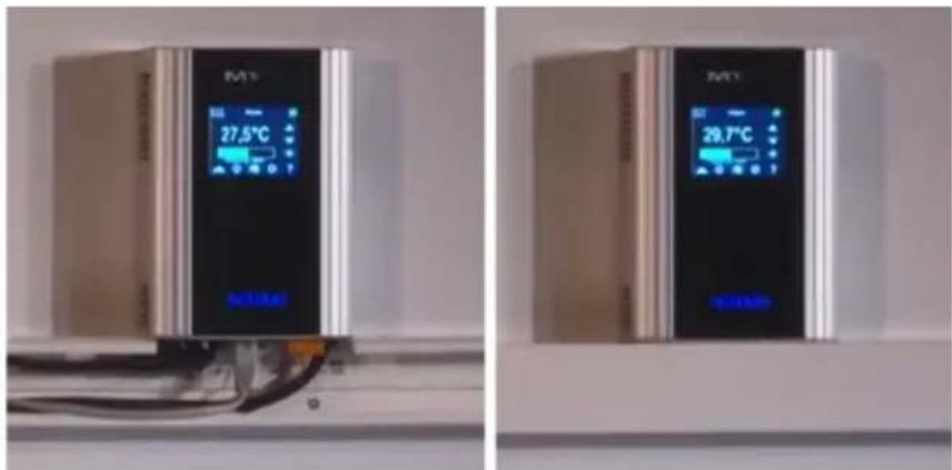
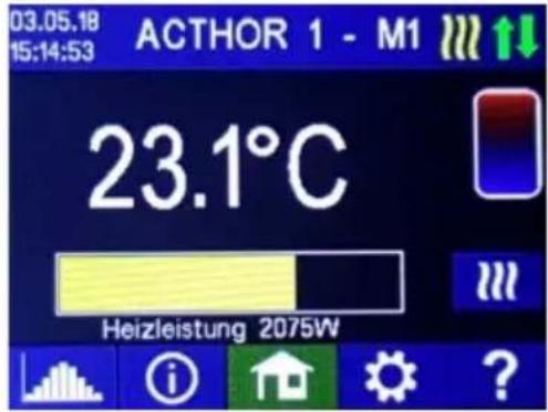
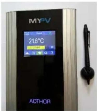
Operation displays
The unit has a touch screen to show operating conditions and for ease of operation.

Never touch the screen with pointed objects or those having sharp edges!
For best use the supplied operator stylus. The holder for the stylus can be stuck on to a surface on or close to the unit with the adhesive patch.
A detailed description of the graphic user interface, the operating modes, the menu guide and the possibilities for setting will be found in the Operating instructions for the unit. The current version is available on www.my-pv.com.
Troubleshooting
The device does not contain any parts that may be repaired by the user. In the event of a fault, please contact your specialist dealer.
Disposal

Packaging material must be either stored or disposed of as appropriate.
Dispose of the product at the end of its service life according to the statutory regulations.
EU declaration of conformity
You can find them at any time on www.my-pv.com
Technical specifications
AC•THOR
| Mains voltage | 230 V, 45-65 Hz |
| Regulated output | 0 to 230 V pure sine0 to 3,000 W max. |
| Relay output | 1 x UM20 V AC 100 mA min.230 V AC 16 A max. |
| Mains connection | Single phase,grounded plug |
| Safeguarding | 16 A tripping characteristic B, C |
| Load connection | Insulated socket for resistive loads |
| Connecting wire | 2.8 m |
| Standby-consumption | < 1.5 W |
| Efficiency | >98 % at rated power |
| Operating temperature range | 0°C to 40 °C |
| Permissible RH | 0-99 % (non-condensing) |
| Storage temperature | -20°C to 70 °C |
| Protection | IP20 |
| Protection class | I |
| Temperature sensor | my-PV digital temperature sensor(5 m) |
| Display | Colour graphic, touch screen 2.83" |
| Warranty | 2 Years |
| Compatible systems | see www.my-pv.com |
| Interfaces | Ethernet RJ45, RS485potential-free inputPWM out, PWM in |
| Weight | 1.5 kg including lead(without wall bracket) |
| Dimension (W x H x D) | 135 x 195 x 65 mmwithout mains cable |
Subject to changes and printing
errors.

my-PV GmbH
Betriebsstraße 12,
A-4523 Neuzeug
www.my-pv.com
AC•THOR®
natural_image
Close-up of a computer motherboard with ventilation slots and connectors (no visible text or symbols)natural_image
Exterior view of a modern office building (no signage)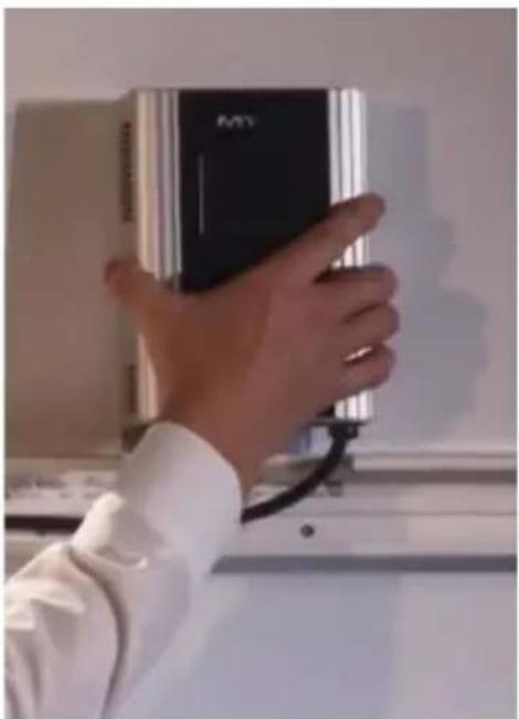
natural_image
Hand holding a black electronic device with a white shirt, against a plain wall (no visible text or symbols)natural_image
Close-up of a computer motherboard with ventilation slots and connectors (no visible text or symbols)natural_image
Metal electrical component mounted on a wall, no visible text or symbols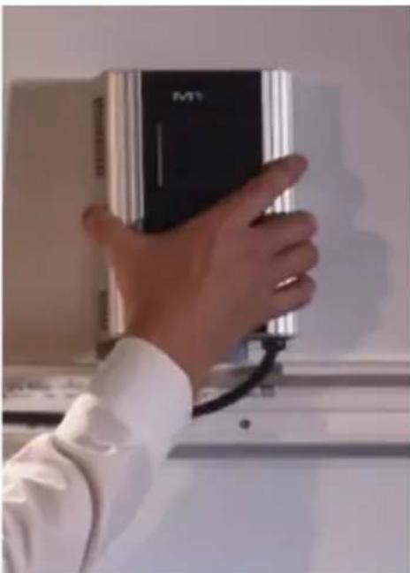
natural_image
Hand holding a black M1 device against a wall, no visible text or symbols on the device itself
natural_image
Close-up of a computer motherboard with ventilation grilles and connectors (no visible text or symbols)natural_image
Exterior view of a modern office building (no signage)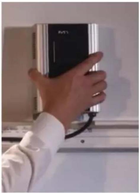
natural_image
Hand holding a black electronic device with a white shirt, against a plain wall background (no visible text or symbols)The current versions are available on www.my-pv.com.
Establishing the automatic connection via router may take as much as a minute!