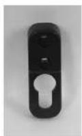
RC-50 - Speaker Energy - Free user manual and instructions
Find the device manual for free RC-50 Energy in PDF.
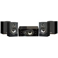
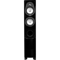
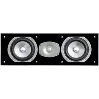
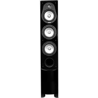
| Product Type | Tower speaker (loudspeaker) from the Reference Connoisseur series |
| Brand | Energy |
| Model | RC-50 |
| Dimensions (approx.) | Height: 100 cm, Width: 20 cm, Depth: 30 cm |
| Weight (approx.) | 20 kg |
| Cabinet material | MDF with vinyl finish |
| Magnetic shielding | Yes (compatible with CRT, plasma, LCD TVs) |
| Connection types | Gold-plated terminals accepting banana plugs, spades, and bare wire |
| Wiring options | Traditional method, bi-wiring, bi-amping |
| Soundfield control (RC-R model) | Bipole/dipole switch and level control for side speakers |
| Included accessories | 4 rubber feet, 4 spikes and spike shoes, 4 set screws, 4 nuts, Allen key, foam plugs (for events) |
| Recommended break-in | 100 hours at moderate volume to achieve optimal performance |
| Warranty | 5 years (parts and labor) subject to presentation of proof of purchase |
| Maintenance and cleaning | Clean with a soft, slightly damp cloth; do not use abrasive or ammonia-based cleaners |
| Safety instructions | Do not expose cones to chemicals; use spikes/stabilizers to prevent tipping |
| Recommended placement | Facing the listening position, 30 cm from side walls, spaced at least 1.5 m apart |
Frequently Asked Questions - RC-50 Energy
User questions about RC-50 Energy
0 question about this device. Answer the ones you know or ask your own.
Ask a new question about this device
Download the instructions for your Speaker in PDF format for free! Find your manual RC-50 - Energy and take your electronic device back in hand. On this page are published all the documents necessary for the use of your device. RC-50 by Energy.
USER MANUAL RC-50 Energy
ENERGY® warrants this product, so the real purchase against any failure resulting from original manufacturing defects in partnership or materials. The warranty is in effect for a period of: Speaker Section-les 1st years, Surowsler Section-or-e 1st year from date of purchase from an authorized ENERGY® owner and is valid only if the original dates bill of sale is preserved when service is required.
The warranty does not cover damage caused by shipping, by accident, miss. or, above, required, unauthorized product modification, failure to follow the instructions for lines in the motor's manual, failure to perform routine maintenance, damage resulting from unauthorized repairs or claims based upon misrepresentations of the warranty by the seller.
WARRANTY SERVICE
If you require service for your ENERGY® speaker(s) at any time during the warranty period, please contact:
1; the dealer from whom you purchased the products).
2) ENERGY NATIONAL SERVICE, 203 Expert Road, Bulletin, N.Y. 14215 Tel: 715-896-9801 cr
3) ENERGY®, a division of Audio Products International Corp., 3641 McN coll Avenue, Toronto, Ontario, Canada. MIX 1G5 Tel: 416-321-1800
4) Additional service centers can be found by checking the ENERGY website: www.energy.vectors.com or, by calling either of the
You will be responsible for transporting the speakers in adequate packaging to protect their from damage in contact and for the shipping costs to as a authorized ENERGY's service centre or to ENERGY? If the product is returned for repair to ENERGY in Toronto or Buffalo, the costs of the return shipment to you will be said by ENERGY, provider, the returns concerned if within the Limited Warranty. The ENERGY Warranty is limited to repair or replacement of ENERGY products. It does not cover any indicators on certain terms of damage of any kind. The provisions in any other terms, packing contracts or literature differ from those specified in this warranty, the terms of the United Warranty prevail.
GARANTIE
GARANTIE AUX ÉTATS-UNIS ET AU CANADA
natural_image
Three black wooden speakers with varying speaker sizes and sound waves (no visible text or labels)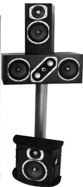
natural_image
Black and white photo of a multi-tiered audio amplifier with four speakers (no text or symbols visible)Energy Ref. Conn.-9 Lang printers 6/20/05 10:00 AM Page 3
owners manual
IMPORTANT SAFETY INSTRUCTIONS – READ CAREFULLY!
We are proud to overcome you as an store of ENERGY® Speaker Systems. Science Communicator Series, ENERGY® Speakers are the result of extensive research into accurate some reproduction and represent the existing edge in operator design and performance. The first components and controller notes are combined with sophisticated manufacturing and quality control procedures, ensure many years of exceptional performance and listening pleasure. Please face time to read all of the instructions contained in this manual to trace certain your system is proper installed and set up for optimal so and reproduction. Be sure to unlock your system carefully. Retain the carton and all packing material for future use.
UNPACKING
Using a knife carefully cut the tape to open the package. Sold the carton flaps back and slide the speaker and packaging from the box. When removing the RC-30, RC-50 or RC-70 following speaker, stand the box upright, cut the tape and slide the speaker from the box. Remove all inner packaging and parts.
IMPORTANT SAFETY INSTRUCTIONS
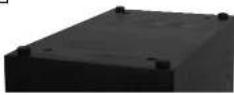
The Reference Commission Series floor standing models RC-50, RC-50 and RC-70 are designed to be used with spices and feet for the speakers' buttons. This important that these are installed properly as they provide stability and able to the cosmetic lack of the speakers.
Contents:
4 - Self adhesive tube bumpers
4 - Protective disc IRC-30, RC-50, RC-70 unit
4 - Spice:RC-30, RC-50, RC-70
4 Nurs:RC 30, RC 50, RC 70 cm y;
1 - Wench (RC-30, RC-50, RC-70 only)
1 - High glass black-pir-thi-sat-base (RC-3C, RC-5D, RC-70 only)
- High density peaking (SC 101)
7 - High density part pugs (BC-1C)
BREAK-IN PROCEDURES
It is V IAT that your new reference. Can a source speakers be allowed to speak in properly before you perform any precise set up procedures, system adjustments, and before you pay them at higher strike levels. The best method of performing the break-in is to play a full range musical passage at a moderate level as long as possible. Utilizing the recent function on your CD or DVD player can assist pretty. Opium sound will not be achieved until approximately 100 ms of playing time. After break-in, the volume level can be increased. Do not play the speakers at high levels until the break-in process has been completed. The transcripts need to "lower us," and until this occurs, damage can result in the transients.
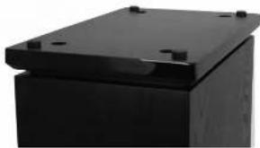
PLINTH/BASES
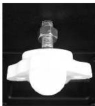
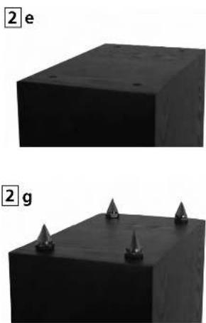
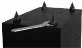
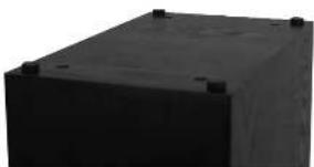
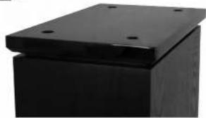
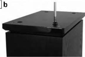
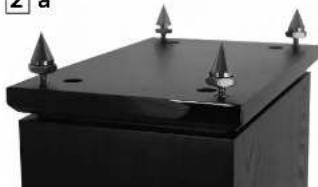
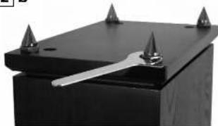
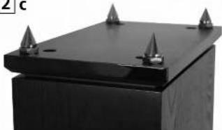
The RC-30, RC-50 and RC-70 (controlling speakers come out of the box with high-glass black pit-thouses attached to their bottom. The pit-thouses are removable if you can choose, by unscrawing the 4 round head machine tells that attach the plantbase in the cabinet. Care should be taken to not damage the speakers or planthouse during removal. Pit-thouses ensure a longer surface area, and therefore produce genres stably to the speaker. Please note diagram 1.
SPIKES
Spikes are inclined with every understanding speaker and are designed to deduce the speaker from the floor. With the speaker upside down the sure to protect the speaker surface when doing this, react the spikes into the stroke insert in the plantees. Using the supplied wire, tighten the cut on each spike, to ensure a sturdy and shake motion is established. The muns also allow for the speaker as a toe to be fine tubes when the speaker is standing up, ensuring the speaker is well and plumb. If your flooring is hardwood or a hard surface like the, latrine flooring, etc.,
The included protective discs are designed to be placed between the spike and the floor, with the packed side down to protect your footing. Simply lay the protective discs on the floor and position the speaker so the point of the spike hits into the hole in the top of the protective disc. If you have removed the climbbase, spikes can be inserted directly into the crested lines in the bottom of the speaker. When using carpeting, ensure no writing bestwith the carpeting is placed by the sides. If you do not wish to use spikes or spikes with protective discs, self-adhesive rubber bunsers are included, or protect, hardwood or hard surface floors. DO NOT SLD THE SPARKS WITH THE SPARK'S INSTALLED, THIS WILL DAMAGE YOUR FOLOWS AND YOUR SPARKERS. Please see diagram 2.
MAGNETIC SHIELDING
While all Reference Connoisseur series speakers are magnetically shielded, stray magnet links to car still exist. Passing your Reference Connoisseur speakers on lap or beside your CRT based television should not cause any interference. In the case where there is some minor dislocations, simply moves the speaker forward or backwards or away from the television or a few inches, this generally resolves the issue. Note: LCD, O.P. of Nasra displays do not suffer from magnetic interference.
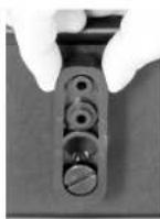
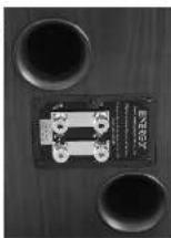
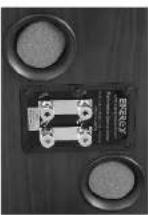
CONNECTING YOUR SPEAKERS
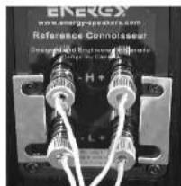
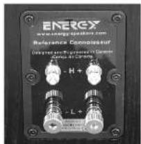
All of the models in the Reference Conno server systems have the same high quality gold plated binding test connectors, se connector to each channel offers the same up run. We should utilize high quality spacer cables up or 12 pages AWGI. The Reference Conno server series will except a variety of connector types including audio clips, batteries packets, or pH type connectors. The best connector in our position is "Spider key" as it provides more compact areas with the terminal and always the binding point to be illuminated for a smart connection. Analogplates and indicators while have preferredness as to which operator type they favor, speak with your Automated F-6/805 retail as to which is the best for your Audio Video System. Best assumed plain sampler wire is more than acceptable, you can change upgrade your stores and/or operators later on.
In the case where you wish to use banana type plugs, simply unscrew the binding post nut in a counter clock wise fashion, until it comes completely off. Remove the plastic red or black insert and reconnect the binding post nut. The plastic insert is a mandatory security measure, as dictated by many local and federal government associations. Please see diagram 3.
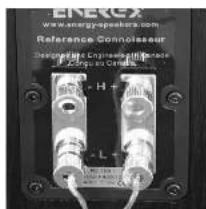
To Connect your speaker system Start at one speaker, and carried one channel at a time, starting with the front speakers. Always ensure that the entire NVP system is powered off before performing any or no actions. The pool, ve and negative feed and black sides of the speaker terminues BLST reach the positive and negative feed and black terminus of the receiver or amplifier. If they do not match, abnormal source and a lack of any response will result. After matching the front spacers, carried the rest all the sprayers to their appropriate channels of the receiver or amplifier. The three correction methods and their realizations indots:
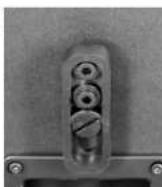
TRADITIONAL CONNECTION METHOD (Please see diagram 4) 1) Using your trace of speaker wire and termination method, connect the speaker cable (including the positive and negative polarities), to the lower set of connectors. Ensure the terminals are tight. The gold "shorting shape" that connects the lower and upper connections must remain in place. 2) Report the procedure for the second speaker
BI-WIRE METHOD (Please see diagram 5)
This method involves using multiple tables and connections, to assess both sets of terminals on the Reference-Consultant Inattypakers simultaneously. The benefit of by swing is to reduce noise, and reduce the list-of-nord of grouting problems, as you will have twice the thickness of cable between the amp and sheaters on the traditional remote would be provided. For more details on the benefits of by swing, please discuss this with your customised I-kay-Gary articles.
NOTE: Before starting, remove the gole "shutting straps", which connect the top and bottom set of input terminals. To remove the strips, loosen all of the connectors and pull the stracs away from the binding parts. Make sure you put them in a sale place for future use.
Energy Ref. Conn.-9 Lang printers 6/20/05 10:00 AM Page 5
owners manual
1) Using your choice of speaker wire and termination method, comes: one speaker cable from the amplifier (inforcing the outline and negative polarities) to the top set of components. Ensure the terminals are right.
7) had, corrected the second cable, from the same channel of your ampilator to the inner set of terminals.
4) Repeat the procedure for the second species.
BI-AMPLIFICATION METHOD (Please see diagram 6)
This connection system involves the use of two separate two channel amplifiers to prevent one set of speakers. The icon is to have one stereo amplifier connected to one speaker, and another identical amplifier powering the second speaker. This is often referred to as "vertical" amplification. It is the only method of better recommendation.
NOTE: Before starting, remove the gold "shorting straps", which connect the top and bottom set of input terminals. To remove the straps, loosen all of the connectors and pull the straps away from the binding posts. Make sure you out them in a safe place for future use.
1) Using a pair choice of speaker wire and transmission methods, connects one speaker cable from the amplifier (imincing the sensitive and negative potentiety) to the most set of respectors. Ensure the terminals are right.
2) Next, connect the second cable from the amplifier's other channel to the bottom set of terminals, again ensuring a right connection 3) Repeat Steps 1 and 2 for the second speaker using the second amplifier
POSITIONING AND INSTALLING YOUR SPEAKERS
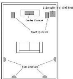
Left and Right Main Speakers (RC-10, RC-30, RC-50, RC-70, RC-LCR) The main speakers are usually placed in the front of the room, on either side of the TV or video projection. They must be prauses a minimum of 6 feet apart, and if the furniture placement allows, except them an inst 10 inches from all walls. In calculating the front pace point, mouse the distance between the speakers themselves one of the following position, your distance from the speakers is too gentle 1:5 times the distance the speakers are apart from each other. For example, at the distance between each speaker and the ordering section is full first from the speakers one bit is free apart from their one another. He will crowd to excellent stage 20 separation and 40 degrees of distance. It is a light starting plane, the room's causes of the furniture placement will own the camera of the speakers. The very best judgment and experiment with speaker declaration. Sight adjustments or provide signit improvements in see familiarity.
RC-10
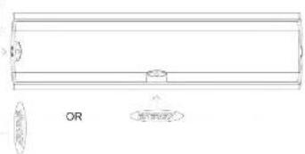
The RC '10 is designed to be used as a door left or right speaker, or as a rear channel speaker. When I staling the Rt. to look like's speaker to a wall, there is an anchor into the back of the speaker, located above the input terminals. The threaded insert is designed specifically for the Energy Macromount ^24 bracket, which is available from your local authorized Energy relation. Please see diagram 7.
The RC-10 includes two foam plugs in the corner, which are designed to be invented into the ports on the rear of the speaker, should the speaker be installed near a wall or in a cabinet. Since the RC-10 is a rear powered speaker, placing it too close to a reinforcing door day, like a wall, will cause undesirable effects. Passing the speaker in a booklet that cabinet will also generate sources with low frequency reproduction. To save this problem simply insert a foam plug into the port on the rear of the speaker. Please see schematic B.
When the IIC-10 is to be installed on a bookshelf or on a stand, please attach the 4-hour bumpers to the portion of the speaker, as this call cannot both the moving surface and the speaker from damage. Simply peel the bumper off its seat and stock it in place on the portion of the speaker, one bumper per corner. The rubber bumper also help deduce the steamer from the bookshelf or stand. Please see diagram 9.
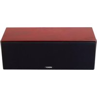
RC-LCR
The RC-LCR is a left-center, right speaker, meaning it has been designed to be used in both a horizontal or vertical location. This design means it can be reached in other places, while according the same description characteristics. Out of the arc the Energy logo IS NOT attached to the right, as this speaker can be placed in various channels. Once the limit orientation of the speaker has been determined, select the appropriate location on the grille, remove the archable protector and apply the logo directly to the grille. Please see diagram 10.
When the HC-LCR is used as a center speaker, it is ideally placed as close to the center of the TV or video projector as possible. This is to ensure that voice and all sounds come from the performer's placement or screen. This may be on top, undermature, or on a shelf with in a wall unit or other furniture. Use the position that provides the best
static quality, but deep in mice safety and room decor as well. The center frame works best when the front of the speaker is flush wall the 70° or the shell is revous. If the center speaker is recovered in its placement, it will sound apart, and outline in character. Please see diagram 11.
When installing the RC-LCR into a cache, please request the two included sort plugs into the pours or the tear of the socket. When the speaker is inserted into a cache, the rent parts will cause an overwhelming of low frequencies and must be plugged, in order to achieve the best possible sound. Care should also be taken to fill the socket, such as the ton of the speaker, with invations as this help to avoid different issues. Your authorized Energy retailer can assist you further with any votes. Please see program 8.
When the RC-LCR is to be installed on two of a television, in a cabinet, or a shelf, please attach the 4 rubber bunsers to the bottom of the speaker, as this will protect both the mounting surface and the speaker from damage. Simply peel the bumper oil its sheet and stick one bumper in each corner on the receiver. Please see diagram 6.
RC-R
The rear speakers can vary greatly in position depending on the room layout, and the furniture placement. The ideal position is either on the side walls, or near walls. Side Wall: this position utilizes the rear walls of the room to reflect sound and graze the "squared" effect.
Real Wall: This is generally used when the side wall position is not available to you, due to L/mixture placement or room dimensions. It is also used in a 6.1 or 7.1 sample or depreciation.
Both turns, ring plots have one large advantages and disadvantages, the discussion offers the best advantage of the entire room to be drawn. The goal of a symmetric speaker during movie reproduction is created as "stochastic" around you. The press details set forth are slowly shaped on equal distance from you as well as the sound of the sound. It is not a very strong or intense environment. The BCT will start sound from both sides of the grater, and is never placed around it can use the keys to reflect the sound the letters. The best meaning position in a 5.1 system is the "Size." Well section, as it makes no interpretation of the sound, it is not a simple way to be seen that the sound size larger than its size. This is important, that the speaker speaks so that it is inside you a slight behind you. The height should be over ear level, at approximately 23 of a height of the wall. A test off of the ground is up to call a good sound point, and the speaker looks like to be first above your head when reading about the general authorities work and in position, places. Please visit ordering: 22
You can also arrive excellent results in the rear wall. They not to place the spots directly into a some time. Once 2 or more first between the edge of the cabinet and the side wall, so the sound can reflect into the room environment. The rear position is usually chosen when your door will not accommodate the side wall position due to, just a wall, a square, or a large opening. It is recommended that the rear center (1:1 system) or dual rear surrounds (1:7) be placed at the same height as the other two rear surround speakers wherever possible.
MOUNTING YOUR RC-R SPEAKERS
NOTE: The RC-R features a very simple well mounting system. Careful attention must be made to mount it securely as the speaker is heavy and damage to the product and/or injury could result from improper mounting. Please follow the directions carefully! Please see diagram 13.
1) Select the moving, put back a fast for your room. 2) Place the well moving towards again, the well in the desc. moving location is marked the center of the two lines with a panel. This is where you want to start the opposite moving hardware to secure fasten a load of 10 kJ and then take it up to the next step. The moving area is using a double unit (e.g., building meters as very poorly in different courses, but the movement depth some takes a full width length s is to be determined by the wall material). 3) If you are moving directly to the body, please ensure that you use the programme under a circuit through a small wall will be quick to avoid movement into the walls. If you are moving directly to the walls, I'll move into all walls from the screen and light. If you move into all walls, I'll move into all walls. See how the secured bolt into the insert in the lack of the bit speaker, ordered above a section at cup, hardening the bolt all the way, and then loose a few turn warmer colors. Please see that the plate if used in black cups on the back of the door, or on other side of the door, and again. See that the speaker up its angle, and insert the bolt head into the large hole. Let the speaker slide down into place.
ENERGY
owners manual
owners manual
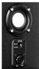
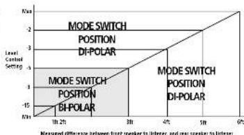
ADJUSTING THE SOUNDFIELD "MANAGEMENT CONTROLS - RC-R
The exclusive and obtained "Soundfield" Management System allows adjustment of the second field in millimeter units, to generate the different
the standard method is efficient to use treatments to compare soil water or soil direct to reflected soil net ratios. The controls permit adjustment of the sound tied
type, and the relative level of the wide being drivers compared in the front drivers. In a relevant case all of the 5 speakers in a home setting would be the same distance
to be left for all of the 2 species who have a normal method to be the same instance from the listener. But when trying to implement a system into your room
environment, this isn't always possible. The direct to reflected sound chart is what allows the air to use distance and depth of the sound. There are two controls on
the "Soundfield Management" Control panel which is located behind the speaker
girl at the right side.
MODE SWITCH - RC-R
The first control is the 2 Position Mode Switch, it allows you to customize the type of soundfield the speaker will produce. Note: Regardless of the switches' section, the two side drivers will continue heretitions.
1) In the "Bicole" post on the two side firing drivers are engaged and are
operating in phase with each other. The resulting sound field is exposed by, and
with some placement, the sound will reflect off from boundaries to create a more so, using a ground field.
2) In the "Di-pole" position the side drivers are active, but are wired out of phase.
from each other, the resulting sound field is even more expansive, and can create an even level effect than the book's space.
3) The RC-R can also be used as a direct linearizer or monoscale speaker - simply
"tan the level control at the way to the 'minimum' position. When at the
min. in position the side-ling driver will ent no sound as el.
LEVEL CONTROL - RC-R
The Level Control adjusts the relative output of the side-living drivers compared to the front driver. At the start, using the side-living driver on 1 dB lower output.
the first drivers. The minimum setting turns the side from drivers completely off.
lanning the PC-R into a direct reducing speaker.
HOW TO SET UP THE CONTROLS - RC-R
1) Measure the distance between the listening position and one of the front
speakers [01] on Diagram "A.1, then measure the distance between the listening position on the rear speaker." [02] on Figure "A.1", Impact the top
postench and the real skewers, 1/2 of Bisquill. It ... subcut the two measurements, and the resulting n-mler is the difference. The bottom scale of
the dirt shows the fillence in distance. See Diagram "A" for assistance, and
Diagram "B" for the actual diagram
NOTE: We do not recommend having the distance between the listener and the
rear speakers to be greater than the front measurement.
- Locate the measure difference on the bottom scale of the graph (Diagram "R")
then follow the line up to where it intersects with the horizontal line and look to
the left scale to see the level control setting recommendation. The graves section shows that the first is should be in R. Grain, Lewis and the out of the death.
shows that the switch should be in 6-Polar Nose, and the rest of the dialc shows the 6-Polar Mode as the recommended mode.
3) Always experiment with the controls, and adjust them to your liking, the chart will
give you a good starting point, out each room is different, and depending on the
3.-4. Location, furniture placement, and materials in the room, adjustments may be included
FINE TUNING
Before beginning any fine hiring, please ensure all connections are properly made:
a 'd your' speakers have had the chance to break-in for a minimum of 100 hours. This will ensure the proper results are achieved.
You have a user in the first company of your whole system will be
that finding a sound in the main condition of your sound, which will be a difference between moderate sound and high quality sound. Reflectors, which are a
part of every recording and music playback, will raise a major effect on your
system's performance. If your room is too "the," meaning there are many bars
sirties are dark values, him thinks and it's very long, you might find the so or good light. If your room is "dead", means there is thick as concrete
heavy furniture and a lot of well coverings, you might find the sound lacks dynamic
energy. To remedy these issues, small changes to your room should be considered as
they generally lead to large improvements in sound cues, Most Listening, most balance, ratheries and cases, but performance and quality advantages for
most balance desires and soon, but people end she maintaining and we are you sure that it is clearly
positioning and self-care plan set, date, duration & duration
The lower bass frequencies are typically the most influenced by your listening room. If you find one bass in your room to be above or even more is certain.
if you find a class in your location to be a level of e-sque line. In certain frequencies, experimenting with placement of the front speakers or their orientation
towards the listening position can alleviate some of these issues. The proximity of
the speakers to room boundaries, like wells, will also affect the bass frequencies.
you find your system lacks class. Let check your connection to make sure your return is in close, then receiving with placement. The longer from can wait, the
less overall less useful, your system will have, but, we have all generally be better
deli-ed. I you position your speakers too close to a room boundary, the less will
typically be exaggerated and ill-delirist. Adjusting your vesters to your mom call
j. Before the best hours. If you are providing a credit-in-one of some more than five miles, please call
If you are experiencing issues with in-sq. q. that ensure your speakers are in these with such other. If this is the rate and rate is still equal to the number
will decrease if this is the case and nothing to turn off, moving the objects does together or being them in shortly enclosing them towards the listening
position) can aid in this respect
When inscaling a surround sound system, all the above holds true. Calibration of
you speaker distances, adjusting dearts and balancing your levels with an 51%
meter are necessary to exceed the most out of your system.
CARE OF FINISH
The Reference Connoisseur series cabinets should be gently cleaned with only a
damp cloth and warm water from time to time, in order to remove any dust or
fingerprints. Do not use an abrasive cleaner, or any type of ammon a based cleaner,
of window type cleaners. To remove a dust from the light cloth, use the cross-attachment on your eyes to clean or a slight is determined vouching at low
dads. Do not touch the speaker zones directly or enter them in contact with water
or cleaning materials, as "is cause in eparable damage.
12 a
12 b
12 b
12 d
13
14
line
| Level Control Setting | Rmax | | --------------------- | ---- | | 0 | -15 | | 2 | -1 | | 4 | -2 | | 6 | -3 |owners manual
DIAGRAMS/FIGURES/DIAGRAMAS
7
natural_image
Close-up of a white mechanical component with a hexagonal bolt head and central hub, mounted on a black surface (no text or symbols visible)8 a
8b
9
11
text_image
Subcoofor/Per Wall Unit Center Channel Front Speakers Rear Speakers10
text_image
OR 4.5mm32
ENERGY
IMPORTANTES CONSIGNES DE SÉCURITÉ – LIRE ATTENTIVE
text_image
ENERG www.energy-speakers.com Reference Connisseur Designed and engineered in Canous Cargus au Canery. H+ L+3 c

text_image
ENERGY www.energy.com/ncnban.com Reference Connocateur Connectors: Connectivity-Connectors Switches: On, On, On, On H+5/6
text_image
www.energie-operators.com Reference Commissant Diversified Rectangular Cable Change in Canada H+owners manual
3b
text_image
ENERGY www.energyspeed.com Reference Commission Designed and Prepared to Design Setup at Canola H+4
text_image
ENERG www.energoposphorus.com Reference Connolasseur Designations Engineering Reference H-1000000000000000000000000000000000000000000000000000000000000000000000000000000000000 L-1ENERGY
ENERGY
DIAGRAMS/FIGURES/DIAGRAMAS
owners manual
2f
natural_image
Close-up of a black rectangular object with three metallic protrusions and a central metallic lever (no visible text or symbols)2 h
natural_image
Exterior view of a black rectangular block with small protrusions (no text or symbols visible)DIAGRAMS/FIGURES/DIAGRAMAS
1 a
natural_image
Close-up of a black rectangular electronic component with mounting holes (no visible text or symbols)1b
natural_image
Close-up of a black rectangular electronic component with a metallic rod inserted, no visible text or symbols2 a
natural_image
Close-up of a black rectangular electronic component with three metallic pins and mounting holes (no visible text or symbols)2b
natural_image
Close-up of a black rectangular electronic component with four triangular pins and a metallic lever (no visible text or symbols)2c
natural_image
Close-up of a black rectangular electronic component with three metallic pins (no visible text or symbols)2d
natural_image
Close-up of a black rectangular electronic component with mounting holes (no visible text or symbols)ENERGY
29
4 - Schusschen (in BC-30, BC-50, BC-70)
4 Spices (in) PC 30, PC 52, PC 70
Aute: LCD, DC-E Plastic tube screen in the E- or E-chelica.
COMO CONECTAR OS SEUS ALTO-
FALANTES
Estas de modificas da Silva. Référence: Consenner, tim a mesma als qualificace des ochemores des hommes de 1er. portano a crochta para zode general esteres as mesmas oções. Veste deve unitar baixos para a auto-falantes de alte qualidade de este 12 salles e (i)RtG. A Sete Believe que Consenra a aguela una ve reçado de omeiras. Fidu éndo espala, benuta, o tipo pliu. Em mais por liti, o melhor ocerer, o e Espaia, enterprise médias de contacto com o emifina e premio e se de unir allo lias por a uma conselho seg. La 10 a Audiófrique, qu'à o valor de 1975. Ote, que o ester, que no ester, que no ester, que no ester, que no ester, que no ester, que no ester, que no ester, que no ester, que no ester, que no ester, que no ester, que no ester, que no ester, que no ester, que no ester, que no ester, que no ester, que no ester, que no ester, que no ester, que n° 16.