CF-50 - Speaker Energy - Free user manual and instructions
Find the device manual for free CF-50 Energy in PDF.
| Brand | Energy |
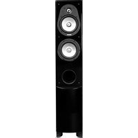
| Model | CF-50 |
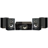
| Product Type | Passive Tower Speaker |
| Series | Connoisseur |
| Magnetic Shielding | Yes |
| Connection Terminals | Gold-plated, accept bananas, spades, plugs |
| Connection Methods | Traditional, bi-wiring, bi-amping |
| Recommended Cable | Gauge up to 12 AWG |
| Break-in Procedure | 100 hours at moderate volume |
| Care and Cleaning | Damp cloth, warm water; do not use abrasive cleaners |
| Box Contents | 4 rubber feet, 1 set of high-density plugs |
| Wall Mounting | Not applicable (tower speaker) |
| Warranty | 5 years (passive speaker), 1 year (subwoofer) |
| After-Sales Service | Contact dealer or ENERGY Speaker Systems |
| Precautions | Do not play at high volume before break-in; do not touch cones |
| Recommended Use | Front main speakers |
| Minimum speaker spacing | 1.8 m |
| Distance from walls | 30 cm or more |
| Recommended Listening Distance | 1.5 times the speaker spacing |
| Compatibility | With receivers/amplifiers, televisions (shielded) |
Frequently Asked Questions - CF-50 Energy
User questions about CF-50 Energy
0 question about this device. Answer the ones you know or ask your own.
Ask a new question about this device
Download the instructions for your Speaker in PDF format for free! Find your manual CF-50 - Energy and take your electronic device back in hand. On this page are published all the documents necessary for the use of your device. CF-50 by Energy.
USER MANUAL CF-50 Energy
natural_image
Illustration of a multi-tiered speaker tower with multiple speakers and circular components (no text or symbols)OWNER'S MANUAL
IMPORTANT SAFETY INSTRUCTIONS — READ CAREFULLY!
We are proud to welcome you as an owner of ENERGY ^® Speaker Systems' Connoisseur Series. ENERGY ^® Speakers are the result of extensive research into accurate sonic reproduction and represent the leading edge in speaker design and performance. The finest components and cabinet materials, combined with sophisticated manufacturing and quality control procedures, ensure many years of exceptional performance and listening pleasure.
Please take time to read all of the instructions contained in this manual to make certain your system is properly installed and set up for optimal sound reproduction. Be sure to unpack your system carefully. Retain the carton and all packing material for future use.
UNPACKING
Using a knife carefully cut the tape to open the package. Fold the carton flaps back and slide the speaker and packaging from the box. When removing the CF-30, CF-50 or CF-70 floorstanding speaker, stand the box upright, cut the tape and slide the speaker from the box. Remove all inner packaging and parts.
CONTENTS:
4 - Self adhesive rubber bumpers (CB-5, CB-10, CB-20, CC-5, CC-10 only)
1 - High density port plug set
BREAK-IN PROCEDURES
It is VITAL that your new Connoisseur speakers be allowed to break-in properly before you perform any precise set up procedures, system adjustments, and before you play them at higher volume levels. The best method of performing the break-in is to play a full range musical passage at a moderate level as long as possible. Utilizing the repeat function on your CD or DVD player can assist greatly. Optimum sound will not be achieved until approximately 100 hours of playing time. After break-in, the volume level can be increased. Do not play the speakers at high levels until the break-in process has been completed. The transducers need to "loosen up", and until this occurs, damage can result to the transducers.
MAGNETIC SHIELDING
While all Connoisseur series speakers are magnetically shielded, stray magnetic fields can still exist. Placing your Connoisseur speakers on top or beside your CRT based television should not cause any interference. In the case where there is some minor discoloration, simply move the speaker forward or backwards or away from the television a few inches, this generally resolves the issue. Note: LCD, DLP and Plasma displays do not suffer from magnetic interference.
owners manual
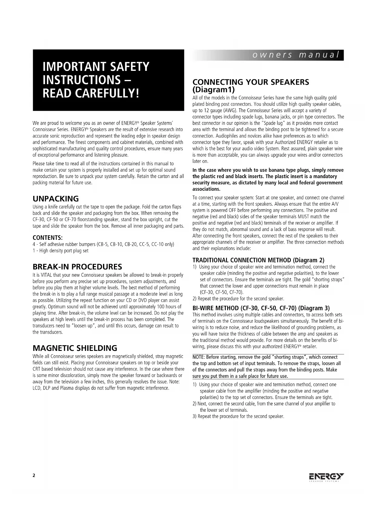
CONNECTING YOUR SPEAKERS (Diagram1)
All of the models in the Connoisseur Series have the same high quality gold plated binding post connectors. You should utilize high quality speaker cables, up to 12 gauge (AWG). The Connoisseur Series will accept a variety of connector types including spade lugs, banana jacks, or pin type connectors. The best connector in our opinion is the "Spade lug" as it provides more contact area with the terminal and allows the binding post to be tightened for a secure connection. Audiophiles and novices alike have preferences as to which connector type they favor, speak with your Authorized ENERGY retailer as to which is the best for your audio video System. Rest assured, plain speaker wire is more than acceptable, you can always upgrade your wires and/or connectors later on.
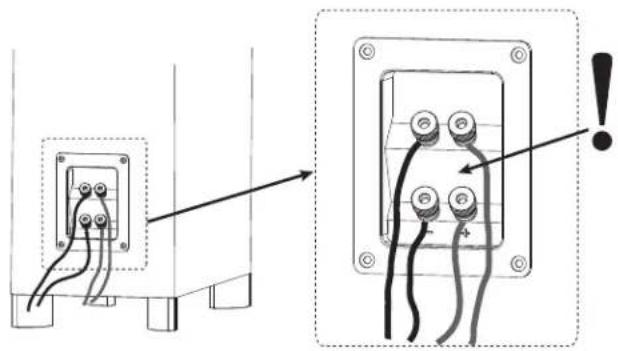
In the case where you wish to use banana type plugs, simply remove the plastic red and black inserts. The plastic insert is a mandatory security measure, as dictated by many local and federal government associations.
To connect your speaker system: Start at one speaker, and connect one channel at a time, starting with the front speakers. Always ensure that the entire A/V system is powered OFF before performing any connections. The positive and negative (red and black) sides of the speaker terminals MUST match the positive and negative (red and black) terminals of the receiver or amplifier. If they do not match, abnormal sound and a lack of bass response will result. After connecting the front speakers, connect the rest of the speakers to their appropriate channels of the receiver or amplifier. The three connection methods and their explanations include:
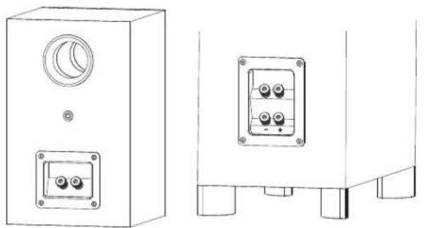
TRADITIONAL CONNECTION METHOD (Diagram 2)
1) Using your choice of speaker wire and termination method, connect the speaker cable (minding the positive and negative polarities), to the lower set of connectors. Ensure the terminals are tight. The gold "shorting straps" that connect the lower and upper connections must remain in place (CF-30, CF-50, CF-70).
2) Repeat the procedure for the second speaker.
BI-WIRE METHOD (CF-30, CF-50, CF-70) (Diagram 3)
This method involves using multiple cables and connectors, to access both sets of terminals on the Connoisseur loudspeakers simultaneously. The benefit of bi-wiring is to reduce noise, and reduce the likelihood of grounding problems, as you will have twice the thickness of cable between the amp and speakers as the traditional method would provide. For more details on the benefits of bi-wiring, please discuss this with your authorized ENERGY ^® retailer.
NOTE: Before starting, remove the gold "shorting straps", which connect the top and bottom set of input terminals. To remove the straps, loosen all of the connectors and pull the straps away from the binding posts. Make sure you put them in a safe place for future use.
1) Using your choice of speaker wire and termination method, connect one speaker cable from the amplifier (minding the positive and negative polarities) to the top set of connectors. Ensure the terminals are tight.
2) Next, connect the second cable, from the same channel of your amplifier to the lower set of terminals.
3) Repeat the procedure for the second speaker.
BI-AMPLIFICATION METHOD (CF-30, CF-50, CF-70) (Diagram 3)
This connection system involves the use of two separate two channel amplifiers to power one set of speakers. The idea is to have one stereo amplifier connected to one speaker, and another identical amplifier powering the second speaker. This is often referred to as "Vertical" Bi-amplification. It is the only method ENERGY ^ recommends.
NOTE: Before starting, remove the gold "shorting straps", which connect the top and bottom set of input terminals. To remove the straps, loosen all of the connectors and pull the straps away from the binding posts. Make sure you put them in a safe place for future use.
1) Using your choice of speaker wire and termination method, connect one speaker cable from the amplifier (minding the positive and negative polarities) to the top set of connectors. Ensure the terminals are tight.
2) Next, connect the second cable, from the amplifier's other channel to the bottom set of terminals, again ensuring a tight connection.
3) Repeat Steps 1 and 2 for the second speaker using the second amplifier.
POSITIONING AND INSTALLING YOUR SPEAKERS
LEFT AND RIGHT MAIN SPEAKERS
(CB-5, CB-10, CB-20, CF-30, CF-50, CF-70)
The main speakers are usually placed in the front of the room, on either side of the TV or video projector. They should be placed a minimum of 6 feet apart, and if the furniture placement allows, keep them at least 12 inches from all walls. To calculate the best placement, measure the distance between the speakers themselves and the listening position. Your distance from the speakers should be roughly 1.5 times the distance the speakers are apart from each other. For example: If the distance between each speaker and the listening position is 9 feet, then the speakers should be 6 feet apart from one another. This will provide excellent stereo separation and imaging for music playback. This is just a starting point, the room's acoustics and furniture placement will vary the placement of the speaker. Use your best judgment and experiment with speaker placement. Slight adjustments can provide significant improvements in performance.
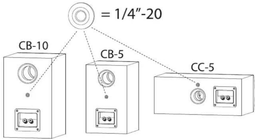
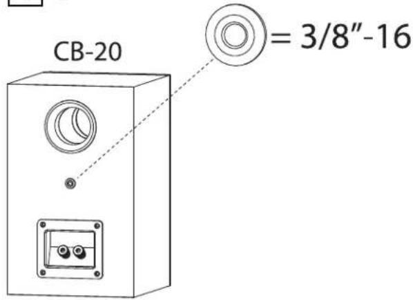
WALL MOUNT OPTIONS (CB-5, CB-10, CB-20, CC-5) (Diagram 4)
These models can be wall mounted using the keyhole or threaded insert on the back. The threaded insert is an imperial 1/4-20 (CB-5, CB-10, CC-5) or 3/8-16 (CB-20) thread and should be compatible with various aftermarket mounting systems.
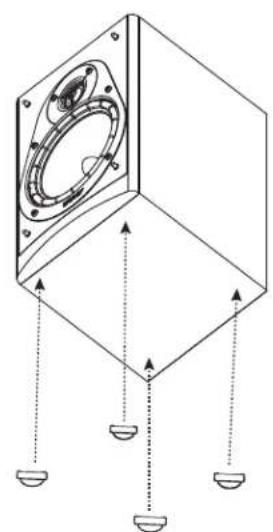
TABLE/STAND MOUNTING (CB-5, CB-10, CB-20, CC-5, CC-10) (Diagram 5)
When the speaker will be installed on a bookshelf or on a stand, please attach the 4 rubber bumpers to the bottom of the speaker, as this will protect both the mounting surface and the speaker from damage. Simply peel the bumper off its sheet and stick it in place on the bottom of the speaker, one bumper per corner. The rubber bumpers also help decouple the speaker from the bookshelf or stand.
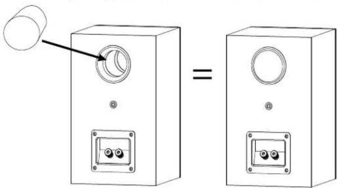
CABINET INSTALLATION (CB-5, CB-10, CB-20, CC-5, CC-10) (Diagram 6)
When installing the speaker into a cabinet, please insert the two included port plugs into the ports on the rear of the speaker. When the speaker is inserted into a cabinet, the rear ports will cause an overemphasis of low frequencies and must be plugged, in order to achieve the best possible sound. Care should also be taken to fill the cabinet, flush to the front of the speaker, with insulation as this helps to avoid diffraction issues. Your authorized Energy retailer can assist you further with any issues.
CR-10 (Diagram 7)
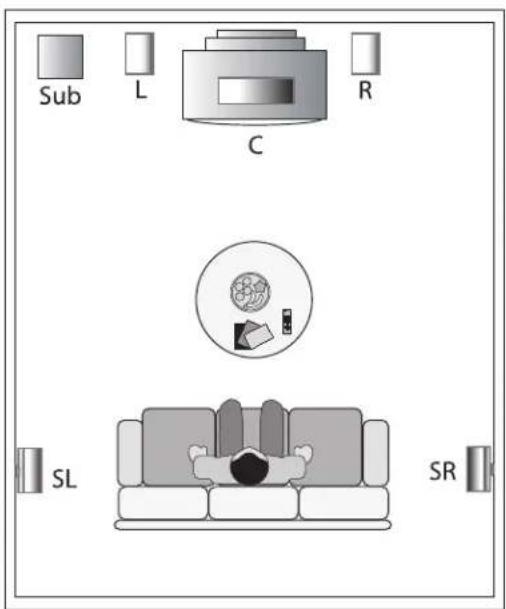
The rear speakers can vary greatly in position depending on the room layout, and the furniture placement. The ideal position is either on the side walls, or rear walls.
Side Wall: This position utilizes the ceiling or rear walls of the room to reflect sound and create the "surround" effect.
Rear Wall: This is generally used when the side wall position is not available to you, due to furniture placement or room dimensions. It is also used in a 6.1 or 7.1 surround configuration.
Both mounting positions have their advantages and disadvantages, the position offering the best coverage of the entire room should be chosen. The goal of the surround speakers during movie reproduction is to create an "atmosphere" around you. The rear channel speakers are ideally placed an equal distance from you as compared to the front speakers. But this is not always possible in a home environment. The CR-10 will emit sound from both sides of the speaker, and is best placed where it can use the ceiling and walls to reflect the sound around the listeners. The best mounting position for a 5.1 system is the Side Wall position, as it makes use of the rooms' ceiling, rear walls, and side walls. It will create a lifelike surround effect and make the room sound larger than it is. In this position, try to mount the speaker so that it is beside you or slightly behind you. The height should be above ear level, at approximately 2/3 of the height of the wall. 6 feet off of the ground is typically a good starting point, and the speaker should be 2 feet above your head when seated. These general guidelines should aid in positioning choices.
You can also achieve excellent results in the rear position. Try not to place the speakers directly into a corner. Leave 2 or more feet between the edge of the cabinet and the side wall, so the sound can reflect into the room environment. The rear position is usually chosen when your room will not accommodate the side wall position due to unequal walls, a doorway, or a large opening, etc. It is recommended that the rear center (6.1 system) or dual rear surrounds (7.1) be placed at the same height as the other two rear surround speakers wherever possible.
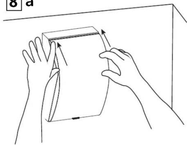
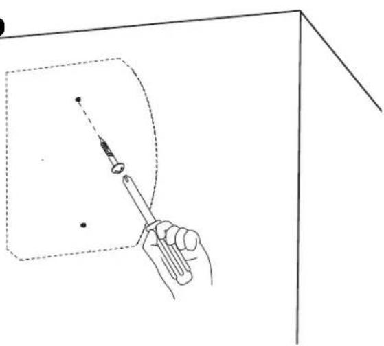
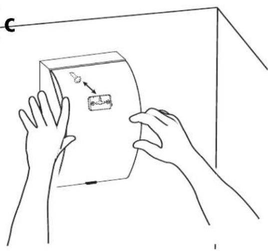
MOUNTING YOUR CR-10 SPEAKERS (Diagram 8)
NOTE: The CR-10 features a very simple wall mounting system. Careful attention must be made to mount it securely as the speaker is heavy and damage to the product and/or injury could result from improper mounting. Please follow the directions carefully!
1) Select the mounting position best suited for your room.
2) Place the speaker vertically against the wall in the desired mounting location and push firmly on the speaker cabinet to mark the wall. This is where you need to insert the appropriate mounting hardware to securely fasten the speaker. Hardware is not included with the speaker, as building materials vary greatly in different countries, but the recommended screw head size is a #8. Screw length is to be determined by the wall material.
3) If you are mounting directly to drywall, please ensure that you use the appropriate anchors, as screws into drywall itself will not provide a secure mount. Insert the anchors AND screws until tight. Try to locate into wall studs wherever possible.
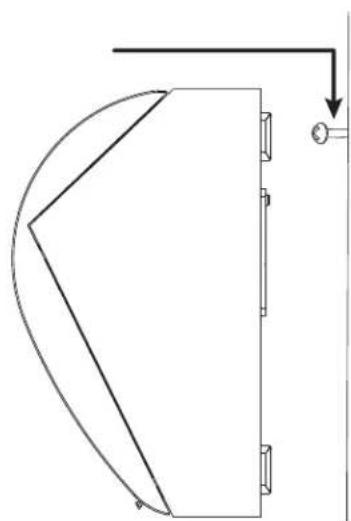
4) Hold the speaker vertically and insert the screw head into the large hole. Let the speaker slide down into place.
BI-POLE/DI-POLE SWITCH - CR-10
The Bi-pole/Di-pole Switch allows you to customize the type of sound field the speaker will produce. Note: Regardless of the switches' position, the two tweeters will continue functioning.
1) In the "Bi-pole" position the two tweeters are engaged and are operating in phase with each other. The resulting sound field is expansive, and with correct placement, the sound will reflect off of room boundaries to create a large sounding surround field.
2) In the "Di-pole" position the tweeters are active, but are wired out of phase from each other. The resulting sound field is even more expansive, and can create an even larger effect than the bi-pole mode.
BI-POLE/DI-POLE SWITCH (CR-10)
| Speaker distance from listening position | Switch Position |
| < 3 ft. (0.91 m) | Bi-Pole |
| > 3 ft. (0.91 m) | Di-Pole |
| Note: Always experiment with the controls, and adjust them to your liking.The chart will give you a good starting point, but each room is different, anddepending on the CR-10's location, furniture placement and materials in the room, adjustments may be necessary. | |
FINE TUNING
Before beginning any fine tuning, please ensure all connections are properly made and your speakers have had the chance to break-in for a minimum of 100 hours. This will ensure the proper results are achieved.
Your listening room is the final component of your audio system and will be the difference between mediocre sound and high quality sound. Reflections, which are a part of every recording and music playback, will have a major effect on your system's performance. If your room is too "live", meaning there are many bare surfaces like glass windows, hard floors and thin furnishings, you might find the sound overly bright. If your room is "dead", meaning there is thick pile carpeting, heavy furniture and a lot of wall coverings, you might find the sound lacks dynamic energy. To remedy these issues, small changes to your room should be considered as they generally lead to large improvements in sound quality. Most listening rooms must balance aesthetics and sound, but patience and small adjustments in positioning and settings can pay huge acoustic dividends.
The lower bass frequencies are typically the most influenced by your listening room. If you find the bass in your room to be uneven or exaggerated in certain frequencies, experimenting with placement of the front speakers or their orientation towards the listening position can alleviate some of these issues. The proximity of the speakers to room boundaries, like walls, will also affect the bass frequencies. If you find your system lacks bass, first check your connections to make sure your system is in phase, then experiment with placement. The further from the wall, the less overall bass output your system will have, but the bass will generally be better defined. If you position your speakers too close to a room boundary, the bass will typically be exaggerated and ill-defined. Adjusting your speakers to your room will generate the best results.
If you are experiencing issues with imaging, first ensure your speakers are in phase with each other. If this is the case and imaging is still an issue, moving the speakers closer together or toeing them in slightly (angling them towards the listening position) can aid in this respect.
When installing a surround sound system, all the above holds true. Calibration of your speaker distances, adjusting delays and balancing your levels with an SPL meter are necessary to extract the most out of your system.
CARE OF FINISH
The Connoisseur Series cabinets should be gently cleaned with only a damp cloth and warm water from time to time, in order to remove any dust or fingerprints. Do not use an abrasive cleaner, or any type of ammonia based cleaners, or window type cleaners. To remove the dust from the grille cloth, use the brush attachment on your vacuum cleaner or a slightly dampened sponge or dust free cloth. Do not touch the speaker cones directly or enter them in contact with water or cleaning materials, as this can cause irreparable damage.
IMPORTANTES CONSIGNES DE SÉCURITÉ – LIRE ATTENTIVEMENT!
MAGNEETISCHE AFSCHERMING
TRADITIONELE AANSLUITING METHODE (Diagram 2)
LINKSE EN RECHTSE HOOFD SPEAKERS (CB-5, CB-10, CB-20, CC-5)
DIAGRAMS/FIGURES/DIAGRAMAS
1
natural_image
Technical line drawings of two electronic device modules with mounting brackets and control knobs (no text or symbols)2 a
natural_image
Diagram showing a device with two connectors and a separate electrical panel (no text or symbols)2 b

text_image
Diagram showing electrical wiring connection to a wall-mounted device, with an arrow indicating the warning of connection to the wall.3
text_image
Diagram showing wiring connection to a wall-mounted device with an exclamation mark indicating warning.4 a
text_image
= 1/4"-20 CB-10 CB-5 CC-5DIAGRAMS/FIGURES/DIAGRAMAS
4 b
text_image
CB-20 = 3/8"-165
natural_image
Technical diagram of a mechanical component with mounting holes and internal cavity (no text or symbols)6
(CB-5, CB-10, CB-20, CC-5, CC-10 only)
text_image
Diagram showing a device being shifted to a circular component, illustrating the equivalence between two identical devices.7 a
text_image
Sub L C R SL SRDIAGRAMS/FIGURES/DIAGRAMAS
7 b
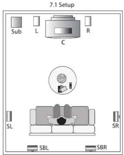
text_image
7.1 Setup Sub L R C SL SR SBL SBR8 a
natural_image
Line drawing of two hands holding a rectangular object with arrows indicating motion (no text or symbols)8b
natural_image
Hand holding a pen with a pointed tip, pointing at a dashed rectangular frame (no text or symbols)8c
natural_image
Line drawing of two hands holding a rectangular object with a small inset showing a magnified view (no text or symbols)8 d
natural_image
Pure technical line drawing of a curved mechanical component with no text or symbols| Model | CF-70 | CF-50 | CF-30 | CB-20 | CB-10 | CB-5 | CC-10 | CC-5 | CR-10 |
| Speaker System | 3-Way Floorstanding Magnetically Shielded Bass Reflex with Front Firing Port | 2.5-Way Floorstanding Magnetically Shielded Bass Reflex with Front Firing Port | 2.5-Way Floorstanding Magnetically Shielded Bass Reflex with Front Firing Port | 2-Way Bookshelf, Magnetically Shielded Bass Reflex with Rear Firing Port | 2-Way Bookshelf, Magnetically Shielded Bass Reflex with Rear Firing Port | 2-Way Bookshelf, Magnetically Shielded Bass Reflex with Rear Firing Port | 2.5-Way Center, Magnetically Shielded Bass Reflex with Rear Firing Port | 2.5-Way Center, Magnetically Shielded Bass Reflex with Rear Firing Port | Bi-Pol/Di-Pole Rear Surround, Suspension |
| Frequency Response (+/- 3dB) | 34Hz - 20kHz | 39Hz - 20kHz | 43Hz - 20kHz | 60Hz - 20kHz | 66Hz - 20kHz | 71Hz - 20kHz | 60Hz - 20kHz | 65Hz - 20kHz | 69Hz - 20kHz |
| Tweeter | 1" (25.4mm) HyperbolicTM aluminum-dome | 1" (25.4mm) HyperbolicTM aluminum-dome | 1" (25.4mm) HyperbolicTM aluminum-dome | 1" (25.4mm) HyperbolicTM aluminum-dome | 1" (25.4mm) HyperbolicTM aluminum-dome | 3/4" (19mm) HyperbolicTM aluminum-dome | 1" (25.4mm) HyperbolicTM aluminum-dome | 3/4" (19mm) HyperbolicTM aluminum-dome | 2 x 3/4" (19mm) HyperbolicTM aluminum-dome |
| Midrange | 5.5" (140mm) w/Ribbed Elliptical Surround" | ||||||||
| Woofer | 2 x 6.5" (165mm) w/Ribbed Elliptical Surround" | 3 x 5.5" (140mm) w/Ribbed Elliptical Surround" | 2 x 5.5" (140mm) w/Ribbed Elliptical Surround" | 6.5" (165mm) w/Ribbed Elliptical Surround" | 5.5" (140mm) w/Ribbed Elliptical Surround" | 4.5" (114mm) w/Ribbed Elliptical Surround" | 2 x 5.5" (140mm) w/Ribbed Elliptical Surround" | 2 x 4.5" (114mm) w/Ribbed Elliptical Surround" | 4.5" (114mm) w/Ribbed Elliptical Surround" |
| Crossover Point(s) | 2kHz, 650 Hz | 2kHz, 1.2kHz | 2kHz, 1.6kHz | 2.2kHz | 2.8kHz | 2.2kHz | 2.6kHz, 1.8kHz | 2.5kHz, 2.1kHz | 2.2kHz |
| Efficiency (Room) | 96dB | 96dB | 90dB | 92dB | 90dB | 89dB | 92dB | 89dB | 89dB |
| Impedence | 4 Ohms Min./ 8 Ohms Nominal | 4 Ohms Min./ 8 Ohms Nominal | 4 Ohms Min./ 8 Ohms Nominal | 4 Ohms Min./ 8 Ohms Nominal | 4 Ohms Min./ 8 Ohms Nominal | 4 Ohms Min./ 8 Ohms Nominal | 4 Ohms Min./ 8 Ohms Nominal | 4 Ohms Min./ 8 Ohms Nominal | 4 Ohms Min./ 8 Ohms Nominal |
| Recommended Amplifier Power | 20-300 w/Channel | 20-250 w/Channel | 20-200 w/Channel | 20-150 w/Channel | 20-125 w/Channel | 20-100 w/Channel | 20-200 w/Channel | 20-150 w/Channel | 20-150 w/Channel |
| Dimensions HxWxD including feet | 40.7 x 8.4 x 15.6" 103.3 x 21.2 x 39.7cm | 38.6 x 7.1 x 14.6" 98.1 x 18 x 37cm | 36 x 7.1 x 12.3" 91.5 x 18 x 31.3cm | 12.2 x 7.6 x 9.1" 31 x 19.2 x 23cm | 11.4 x 7.1 x 8.5" 29 x 18 x 21.6cm | 8.7 x 5.7 x 7.9" 22 x 14.5 x 20cm | 7.1 x 19.7 x 9.9" 18 x 50 x 25.2cm | 14 x 5.7 x 8" 35.5 x 14.5 x 20.3cm | 10.6 x 6.9 x 6.3" 27 x 17.5 x 16cm |
| Units/Carton | 1 | 1 | 1 | 2 | 2 | 2 | 1 | 1 | 2 |
| Product Weight (Single) | 45.3 lbs / 20.5 kg | 39.3 lbs / 17.8 kg | 30.8 lbs / 14 kg | 11.3 lbs / 5.1 kg | 8.9 lbs / 4 kg | 6.6 lbs / 3 kg | 17.4 lbs / 7.9 kg | 10.7 lbs / 4.9 kg | 5.2 lbs / 2.4 kg |
| Packed Weight | 53.2 lbs / 24.1 kg | 45.3 lbs / 20.5 kg | 36.2 lbs / 16.4 kg | 26.5 lbs / 12 kg | 21.4 lbs / 9.7 kg | 18.8 lbs / 8.5 kg | 20.5 lbs / 9.3 kg | 12.8 lbs / 5.8 kg | 14 lbs / 6.3 kg |
| Inputs | Dual Gold Plated 5-Way Binding Posts | Dual Gold Plated 5-Way Binding Posts | Dual Gold Plated 5-Way Binding Posts | Gold Plated 5-Way Binding Posts | Gold Plated 5-Way Binding Posts | Gold Plated 5-Way Binding Posts | Gold Plated 5-Way Binding Posts | Gold Plated 5-Way Binding Posts | Gold Plated 5-Way Binding Posts |
| Finishes | HGB Baffle with Black Ash Cabinet | HGB Baffle with Black Ash Cabinet | HGB Baffle with Black Ash Cabinet | HGB Baffle with Black Ash Cabinet | HGB Baffle with Black Ash Cabinet | HGB Baffle with Black Ash Cabinet | HGB Baffle with Black Ash Cabinet | HGB Baffle with Black Ash Cabinet | Black Ash Cabinet |
| Mounting Options | Threaded insert (3/16" - 16) | Threaded insert (1/4" - 20) | Threaded insert (1/4" - 20) | Threaded insert (1/4" - 20) | Built-in Keyhole Slots | ||||
| Included Accessories | Manual, Port Plug | Manual, Port Plug | Manual, Port Plug | Manual, Port Plugs Rubber Bumpers | Manual, Port Plugs Rubber Bumpers | Manual, Port Plugs Rubber Bumpers | Manual, Port Plugs Rubber Bumpers | Manual, Port Plugs Rubber Bumpers | Manual |
Specifications subject to change without notice.
WARRANTY
GARANTIE
LIMITED WARRANTY POLICY IN THE UNITED STATES AND CANADA
ENERGY ^® warrants this product to the retail purchaser against any failure resulting from original manufacturing defects in workmanship or materials. The warranty is in effect for a period of: Passive Speakers: five (5) years, Powered Subwoofers including the speaker - one (1) year from date of purchase from an authorized ENERGY ^® dealer and is valid only if the original dated bill of sale is presented when service is required.
The warranty does not cover damage caused during shipment, by accident, misuse, abuse, neglect, unauthorized product modification, failure to follow the instructions outlined in the owner's manual, failure to perform routine maintenance, damage resulting from unauthorized repairs or claims based upon misrepresentations of the warranty by the seller.
WARRANTY SERVICE
If you require service for your ENERGY® Speaker Systems speaker(s) at any time during the warranty period, please contact:
1) the dealer from whom you purchased the product(s), or
2) ENERGY ^® Speaker Systems SERVICE – Tel: 1 (866) 441-8208.
3) Additional service centers can be found by checking the ENERGY *Speaker Systems website: www.energy-speakers.com.
You will be responsible for transporting the speakers in adequate packaging to protect them from damage in transit and for the shipping costs to an authorized ENERGY® Speaker Systems service center or to ENERGY® Speaker Systems. If the product is returned for repair to ENERGY® Speaker Systems the costs of the return shipment to you will be paid by ENERGY® Speaker Systems, provided the repairs concerned fall within the Limited Warranty. The ENERGY® Speaker Systems Warranty is limited to repair or replacement of ENERGY® Speaker Systems products. It does not cover any incidental or consequential damage of any kind. If the provisions in any advertisement, packing cartons or literature differ from those specified in this warranty, the terms of the Limited Warranty prevail.