
NC40G - Stapler HiKOKI - Free user manual and instructions
Find the device manual for free NC40G HiKOKI in PDF.
| Product type | Gas masonry stapler (nailer) |
| Brand | HiKOKI |
| Model | NC40G |
| Dimensions (L x H x W) | 420 mm x 352 mm x 108 mm |
| Weight | 3.7 kg |
| Battery power | Ni-Cd battery 7.2 V (EB714S, 1.4 Ah) |
| Gas power | Fuel cell (hydrocarbon, 40 g / 80 ml) |
| Applicable nails | Diameter 2.6 mm, lengths 15–40 mm (smooth, indented, ring) |
| Magazine capacity | 40 nails (4 strips) |
| Operating temperature | 0 °C to 40 °C |
| Charger | UC7SD, 230 V AC, 50 Hz, charging time approx. 60 min |
| Included accessories | Safety glasses, charger, case, hex key |
| Operation | Sequential trip mechanism, safety lock |
| Applications | Fastening wood, thin steel or stops to concrete |
| Maintenance | Clean the magazine, lubricate with HiKOKI lubricant, check screws |
| Sound level | Sound power 108 dB(A), sound pressure 99 dB(A) |
| Vibrations | 3.5 m/s² (characteristic value) |
| Spare parts | List available from HiKOKI after-sales service |
| Warranty | Repairs exclusively by HiKOKI authorized service |
Frequently Asked Questions - NC40G HiKOKI
User questions about NC40G HiKOKI
0 question about this device. Answer the ones you know or ask your own.
Ask a new question about this device
Download the instructions for your Stapler in PDF format for free! Find your manual NC40G - HiKOKI and take your electronic device back in hand. On this page are published all the documents necessary for the use of your device. NC40G by HiKOKI.
USER MANUAL NC40G HiKOKI
natural_image
Technical line drawing of a mechanical device with heat exchanger and wheels (no text or symbols)Read through carefully and understand these instructions before use. Diese Anleitung vor Benutzung des Werkzeugs sorgfältig durchlesen und verstehen. Lire soigneusement et bien assimiler ces instructions avant usage. Prima dell'uso leggere attentamente e comprendere queste instruzioni. Deze gebruiksaanwijzing s.v.p. voor gebruik zorgvuldig doorlezen. Leer cuidadosamente y comprender estas instrucciones antes del uso.
Handling instructions Bedienungsanleitung Mode d'emploi Istruzioni per l'uso Gebruiksaanwijzing Instrucciones de manejo
1
natural_image
Technical line drawing of a battery pack with labeled part (16), no text or symbols present
natural_image
Line drawing of a portable electrical device with a cord and plug, labeled with number 19 (no text or symbols on the device itself)2
3

4

5

natural_image
Line drawing of a mechanical component with numbered annotation (18), no readable text or symbols present6
7
8

9

1011

natural_image
Illustration of hands operating a fastener with a tool, showing mechanical components and motion direction (no text or symbols)
1213

natural_image
Technical line drawing of a mechanical assembly with no visible text or symbols


natural_image
Illustration of a hand holding a device with a cylindrical component and a battery nearby (no text or symbols)| English Deutsch Français | |||
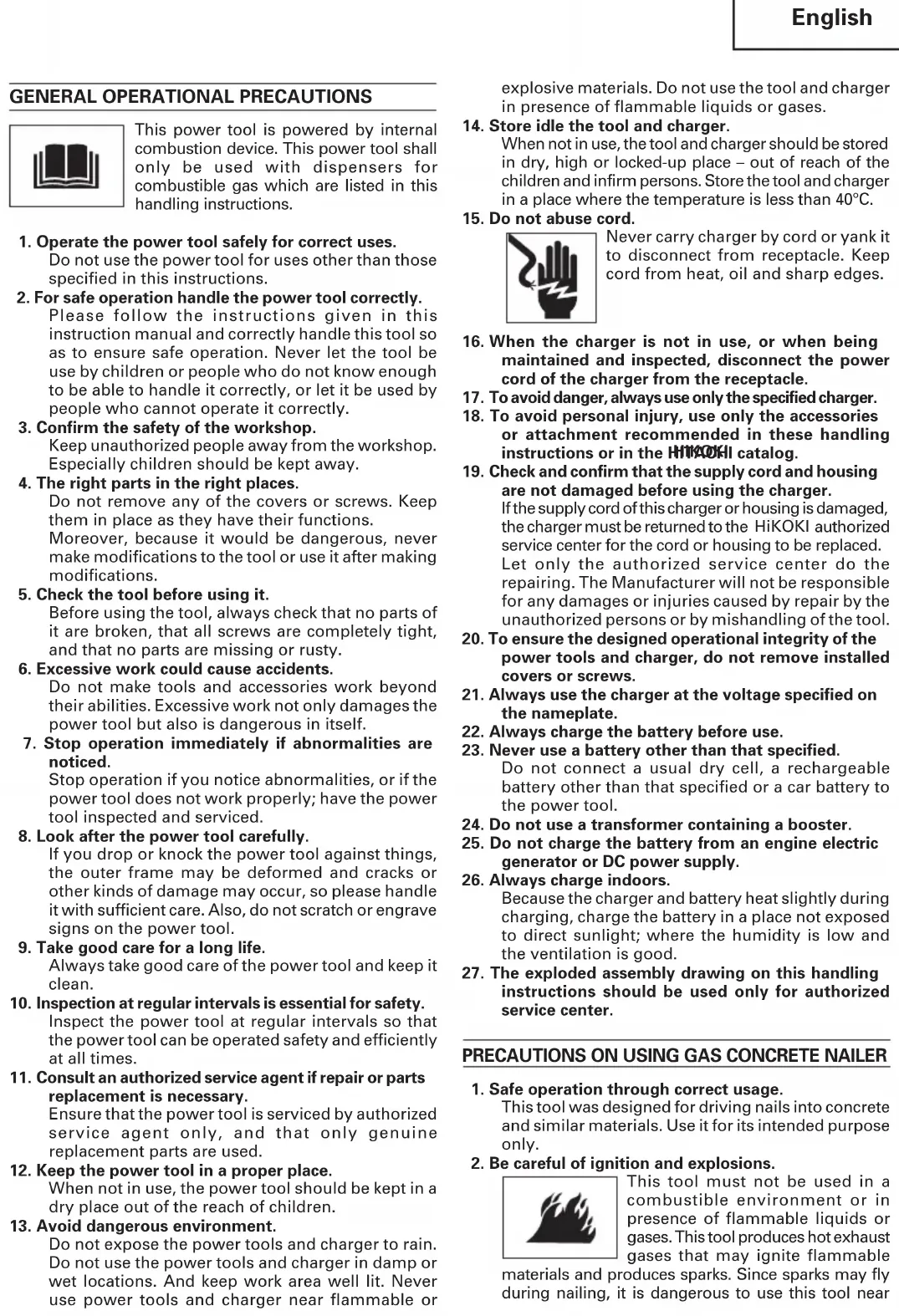
| 1 | Top cover Obere Abdeckung Couvercle supérieur | ||
| 2 | Handle Handgriff Poignée | ||
| 3 | Housing Gehäuse Logement | ||
| 4 | Chamber Kammer Chambre | ||
| 5 | Piston Kolben Piston | ||
| 6 | Driver blade Schraubenzieherklinge | Lame d'entraînement | |
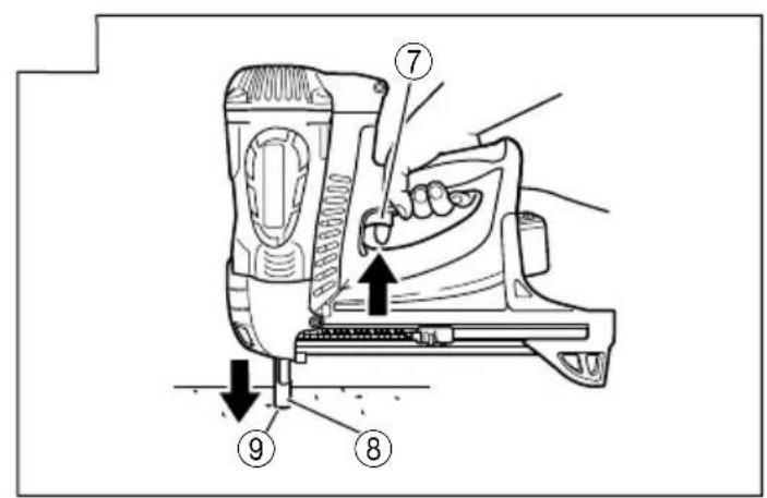
| 7 | Trigger Auslöser Détente | ||
| 8 | Push lever Auslösesicherung Bras. | de contact | |
| 9 | Firing head (Outlet) Schusskopf (Auslass) | Tête de clouage | (sortie) |
| 10 | Magazine | Magazin | Magasin |
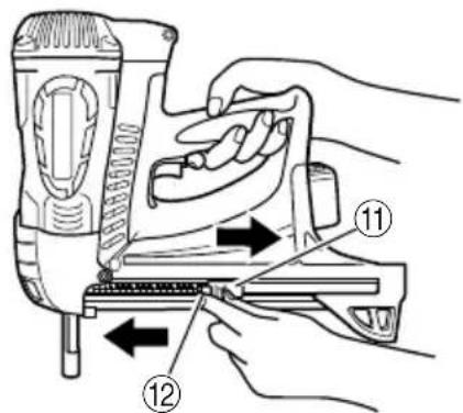
| 11 | Feeder Knob | Zuführungsknopf | Bouton de l'alimenteur |
| 12 | Nail feeder (B) | Nagelschieber (B) | Alimenteur de clous (B) |
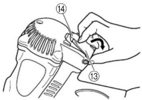
| 13 | Cell Cover | Zellenabdeckung | Couvercle de la pile |
| 14 | Latch | Riegel | Languette |
| 15 | Adapter | Adapter | Adaptateur |
| 16 | Battery | Akku | Batterie |
| 17 | Latch (Battery) | Riegel (Akku) | Verrou (Batterie) |
| 18 | Indicator light | Anzeigeleuchte | Témoin |
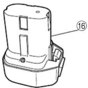
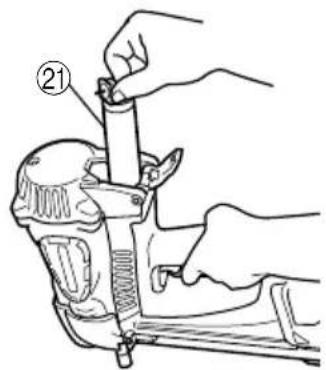
| 19 | Charger | Ladegerät | Chargeur |
| 20 | Pilot lamp | Kontrollleuchte | Lampe témoin |
| 21 | Fuel cell | Brennstoffzelle | Pile à combustible |
| 22 | Metering valve | Dosierventil | Soupape de réglage |
| 23 | Stem | Stift | Tige |
| 24 | Cap | Kappe | Capuchon |
| 25 | Nail stopper Nagelstopper | Coinceur de clous | |
| 26 | Nose cap | Nasenkappe | Capuchon de bec |
| 27 | KnobItaliano Nederlands Español | Drehknopf Bouton | |
| 1 | Coperchio anteriore Kap Protector superior | ||
| 2 | Manopola Greep Mango | ||
| 3 | Sede Omhulsel Alojamiento | ||
| 4 | Camera Magazijn Cámara | ||
| 5 | Pistone Zuiger Pistón | ||
| 6 | Lama Aandrijfblad Cuchilla impulsora | ||
| 7 | Grilletto Trekker Gatillo | ||
| 8 | Leva di spinta Veiligheidshendel Palanca de empuje | ||
| 9 | Testata di sparo (uscita) | Afvuurkop (uitlaat) | Cabezal de disparo (salida) |
| 10 | Contenitore | Magazijn Cargador | |
| 11 | Pulsante alimentatore | Toevoerknop | Botón del alimentador |
| 12 | Alimentatore chiodi (B) | Spijkertoevoer (B) | Alimentador de clavos (B) |
| 13 | Coperchio cella | Gaspatroonafdekking | Protector de la célula |
| 14 | Nottolino | Klink | Cierre |
| 15 | Adattatore | Adapter | Adaptador |
| 16 | Batteria Batterij | Batería | |
| 17 | Bloccaggio (batteria) | Klink (Batterij) | Cierre (Batería) |
| 18 | Luce di indicazione | Indicatielampje | Luz indicadora |
| 19 | Caricatore | Oplader | Cargador |
| 20 | Luce pilota | Controlelampje | Luz del piloto |
| 21 | Cella carburante | Gaspatroon | Celda de combustible |
| 22 | Valvola di misurazione | Meetklep | Válvula de medición |
| 23 | Supporto | Steel Vástago | |
| 24 | Tappo | Kap Tapa | |
| 25 | Ferma chiodi | Spijkerstopper | Tapón de clavo |
| 26 | Tappo del naso | Neuskap | Tapa para el morro |
| 27 | Pomello | Knop | Botón |
GENERAL OPERATIONAL PRECAUTIONS

This power tool is powered by internal combustion device. This power tool shall only be used with dispensers for combustible gas which are listed in this handling instructions.
- Operate the power tool safely for correct uses.
Do not use the power tool for uses other than those specified in this instructions.
- For safe operation handle the power tool correctly.
Please follow the instructions given in this instruction manual and correctly handle this tool so as to ensure safe operation. Never let the tool be use by children or people who do not know enough to be able to handle it correctly, or let it be used by people who cannot operate it correctly.
- Confirm the safety of the workshop.
Keep unauthorized people away from the workshop. Especially children should be kept away.
- The right parts in the right places.
Do not remove any of the covers or screws. Keep them in place as they have their functions.
Moreover, because it would be dangerous, never make modifications to the tool or use it after making modifications.
- Check the tool before using it.
Before using the tool, always check that no parts of it are broken, that all screws are completely tight, and that no parts are missing or rusty.
- Excessive work could cause accidents.
Do not make tools and accessories work beyond their abilities. Excessive work not only damages the power tool but also is dangerous in itself.
- Stop operation immediately if abnormalities are noticed.
Stop operation if you notice abnormalities, or if the power tool does not work properly; have the power tool inspected and serviced.
- Look after the power tool carefully.
If you drop or knock the power tool against things, the outer frame may be deformed and cracks or other kinds of damage may occur, so please handle it with sufficient care. Also, do not scratch or engrave signs on the power tool.
- Take good care for a long life.
Always take good care of the power tool and keep it clean.
- Inspection at regular intervals is essential for safety.
Inspect the power tool at regular intervals so that the power tool can be operated safety and efficiently at all times.
- Consult an authorized service agent if repair or parts replacement is necessary.
Ensure that the power tool is serviced by authorized service agent only, and that only genuine replacement parts are used.
- Keep the power tool in a proper place.
When not in use, the power tool should be kept in a dry place out of the reach of children.
- Avoid dangerous environment.
Do not expose the power tools and charger to rain. Do not use the power tools and charger in damp or wet locations. And keep work area well lit. Never use power tools and charger near flammable or
explosive materials. Do not use the tool and charger in presence of flammable liquids or gases.
- Store idle the tool and charger.
When not in use, the tool and charger should be stored in dry, high or locked-up place – out of reach of the children and infirm persons. Store the tool and charger in a place where the temperature is less than 40^ C.
- Do not abuse cord.

Never carry charger by cord or yank it to disconnect from receptacle. Keep cord from heat, oil and sharp edges.
-
When the charger is not in use, or when being maintained and inspected, disconnect the power cord of the charger from the receptacle.
-
To avoid danger, always use only the specified charger.
-
To avoid personal injury, use only the accessories or attachment recommended in these handling instructions or in the HAKOH catalog.
-
Check and confirm that the supply cord and housing are not damaged before using the charger. If the supply cord of this charger or housing is damaged, the charger must be returned to the HiKOKI authorized service center for the cord or housing to be replaced. Let only the authorized service center do the repairing. The Manufacturer will not be responsible for any damages or injuries caused by repair by the unauthorized persons or by mishandling of the tool.
-
To ensure the designed operational integrity of the power tools and charger, do not remove installed covers or screws.
-
Always use the charger at the voltage specified on the nameplate.
-
Always charge the battery before use.
-
Never use a battery other than that specified.
Do not connect a usual dry cell, a rechargeable battery other than that specified or a car battery to the power tool.
-
Do not use a transformer containing a booster.
-
Do not charge the battery from an engine electric generator or DC power supply.
-
Always charge indoors.
Because the charger and battery heat slightly during charging, charge the battery in a place not exposed to direct sunlight; where the humidity is low and the ventilation is good.
- The exploded assembly drawing on this handling instructions should be used only for authorized service center.
PRECAUTIONS ON USING GAS CONCRETE NAILER
- Safe operation through correct usage.
This tool was designed for driving nails into concrete and similar materials. Use it for its intended purpose only.
- Be careful of ignition and explosions.

This tool must not be used in a combustible environment or in presence of flammable liquids or gases. This tool produces hot exhaust gases that may ignite flammable
materials and produces sparks. Since sparks may fly during nailing, it is dangerous to use this tool near
lacquer, paint, benzine, thinner, gasoline, gas, adhesives and similar inflammable substances as they may ignite or explode. Under no circumstances should this tool therefore be used in the vicinity of such inflammable material.
3. Explosion and fire hazard.

The fuel cell is an aerosol dispensers with flammable contents.
Pressured container and the propellant will remain in the fuel cell. Failure to follow instructions may result in explosion or fire.
Keep the power tool, fuel cells and battery away from sunshine and from temperature exceeding 50^ C ( 120^ F). Fuel cell and/or battery may burst, releasing flammable gas.

Do not pierce or burn the container, even after use.
Do not incinerate, refill, reclaim or recycle the fuel cell.
Do not spray to a naked flame or
any incandescent material.
Keep away from ignition sources – No smoking.
Keep out of the reach of children.
4. Always wear eye protection (protective goggles).

When operating the power tool, always wear eye protection, and ensure that surrounding people wear eye protection too.
The possibility of fragments of the nails that were not properly hit entering the
eye is a threat to sight. Eye protection can be bought at any hardware store. Always wear eye protection while operating this tool. Use either eye protection or a wide vision mask over prescription glasses.
Employers should always enforce the use of eye protection equipment.
5. Protect your ears and head.
When engaged in nailing work please wear ear mufflers and head protection. Also, depending on condition, ensure that surrounding people also wear ear mufflers and head protection.
6. Use outside or well-ventilated areas.

This tool exhausts carbon monoxide which are a danger to health when inhaled.
This tool shall not be used in enclosed or poorly ventilated areas.
Do not inhale.
7. Pay attention to those working close to you.
It would be very dangerous if nails that were not properly driven in should hit other people. Therefore, always pay attention to the safety of the people around you when using this tool. Always make sure that nobody's body, hands or feet are close to the nail outlet.
8. Never point the nail outlet towards people.

Always assume the tool contains fasteners.
If the nail outlet is pointed towards people, serious accidents may be caused if you mistakenly discharge
the tool. When connecting and disconnecting the battery or fuel cell, during nail loading or similar
operations, be sure the nail outlet is not pointed towards anyone (including yourself). Even when no nails are loaded at all, it is dangerous to discharge the tool while pointing it at someone, so never attempt to do so. No horseplay. Respect the tool as a working implement.
9. Before using the power tool, check the push lever.
The Push Lever and Chamber operate in conjunction for this device.
Before using the power tool make sure to check that the push lever operate properly. Without nails, fuel cell and battery loaded into the power tool, check the following.
If abnormal operation occurs, do not use the power tool until it has been inspected and repaired.
○Pull the Feeder knob with the device facing upward and press down the Push lever then confirm that the Push lever securely returns to its original position.
The Push lever operation becomes especially heavy in low temperatures and drive operations may not function.
With pulling back the feeder knob, the push lever must move smoothly.
With pulling back the feeder knob, the trigger must move smoothly.
Furthermore, with regard to the push lever, please note that it must never be modified or removed.
10. Use specified nails only.
Never use nails other than those specified and described in these instructions.
11. Be careful when connecting the battery.
When connecting the battery and loading nails in order not to fire the tool by mistake, make sure of the followings.
○Do not touch the trigger.
○Do not allow the firing head to contact with any surface.
○Keep the firing head down.
Strictly observe the above instructions, and always make sure that no part of the body, hands or legs is ever in front of the nail outlet.
12. Do not carelessly place your finger on the trigger.
Do not place your finger on the trigger except when actually nailing. If you carry this tool or hand it to someone while having your finger on the trigger, you may inadvertently discharge a nail and thus cause an accident.
13. Press the nail outlet firmly against the material to be nailed.
When driving in nails, press the nail outlet firmly against the material to be nailed. If the outlet is not applied properly, the nails may rebound.
14. Keep hands and feet away from the firing head when using.

It is very dangerous for a nail to hit the hands or feet by mistake.
15. Do not touch around the exhaust outlet.

This tool produces hot exhaust gases that may flammable materials. The push lever and nose will become hot and get heated up after prolonged or rapid use.
Do not touch with bare hands.
16. Beware of the tool's kickback.
Do not approach the top of the tool with your head etc. during operation. This is dangerous because the tool may recoil violently if the nail currently being driven in comes into contact with a previous nail or a knot in the workpiece.
17. Take care when nailing the corners of workpiece.
When nailing thin boards, the nails may pass right through, as may also be the case when nailing the corners of workpiece due to deviation of the nails. In such cases, always make sure that there is no one (and nobody's hands or feet; etc.) next to the workpiece you are going to nail.
18. Simultaneous nailing on both sides of the same wall is dangerous.
Under no circumstances should nailing be performed on both sides of a wall at the same time. This would be very dangerous since the nails might pass through the wall and thus cause injuries.
19. Do not use the power tool on scaffoldings, ladders.
The power tool shall not be used for specific application for example:
- when changing one driving location to another involves the use of scaffoldings, stairs, ladders or ladder alike constructions, e.g. roof laths,
– closing boxes or crates,
- fitting transportation safety systems e.g. on vehicles and wagons
20. Disconnect the battery and fuel cell and take out any nails left in the magazine after use.
Disconnect the battery and fuel cell from the tool before doing tool maintenance, cleaning a jammed fastener, leaving work area, moving tool to another location, or after use. It is very dangerous for a nail to be fired by mistake.
21. When removing a nail which has become stuck, make sure to first of all disconnect the battery and fuel cell.
When removing a nail which has become stuck in the nail outlet, first of all make sure to disconnect the battery and fuel cell inside the power tool.
Accidental firing of the nail could be very dangerous.
22. The operating environment for this device is between 0°C (32°F) and 40°C (104°F) so ensure use within this temperature range. The device may fail to operate below 0°C (32°F) or above 40°C (104°F).
23. Always charge the battery at an ambient temperature of 0–40°C.
A temperature of less than 0^ C will result in over charging which is dangerous. The battery cannot be charged at a temperature greater than 40^ C.
The most suitable temperature for charging is that of 20–25°C.
24. Do not use the charger continuously.
When one charging is completed, leave the charger for about 15 minutes before the next charging of battery.
25. Do not allow foreign matter to enter the hole for connecting the rechargeable battery.
26. Never disassemble the rechargeable battery or charger.
27. Never short-circuit the rechargeable battery.

Short-circuiting the battery will cause a great electric current and overheat. It results in burn or damage to the battery.
28. Do not dispose of the battery in fire.
If the battery is burnt, it may explode.
29. Using an exhausted battery will damage the charger.
30. Bring the battery to the shop from which it was purchased as soon as the post-charging battery life becomes too short for practical use.
Do not dispose of the exhausted battery.
31. Do not insert objects into the air ventilation slots of the charger.
Inserting metal objects or flammable into the charger air ventilation slots will result in an electrical shock hazard or damage to the charger.
32. Do not inhale its contents.

In case of being inhaled; the person affected should be taken into the open air and brought into a comfortable position.
33. Expanding gases cause low temperatures.
Fluid gases might cause injuries when getting in touch with skin or eyes.
– In case of contact with skin; wash the contact surface carefully with warm water and soap and apply a skin cream when dry.
– In case of contact with eyes; rinse the open eyes under running water.
Contact a doctor if necessary.
34. Fuel cells.
Store in well-ventilated area. Do not store above 50^ (120°F) (e.g. direct sunlight or in a vehicle). Do not expose to an open flame and sparks.
Do not puncture or open the fuel cell.
Do not refill, reclaim or recycle the fuel cell.
Dispose of according to local regulations for aerosol products.
Do not dispose of fuel cell with other scrap for recycling.
Keep out of reach of children.
35. Transportation/Storage.
Transportation
Shipment per mail is not allowed.
- Transportation of small quantities for own use in private car is allowed without shipping papers and emergency card.
- Observe temperature limit of 50^ (120°F).
Storage
- Do not store in passages, entry halls, near doors/exit or attic.
– Sales booths should not be close exits.
– A fire extinguisher of 6 kg, class A, B, C must be available.
– Packages should be stacked up not to fall to the ground.
- Store rooms must not take more than 20m^2 of room surface.
- Do not store together with pyrotechnical goods.
– The quantity stored in sales rooms should not exceed daily sales.
- Tools with an open flame or high temperature must not be operated near fuel cells.
– Fuel cells must not be displayed in shop windows.
SPECIFICATIONS
- Gas Concrete Nailer (NC40G)
| Type of power Piston reciprocating | |
| Applicable nails ø 2.6 mm (.102") See Fig. | |
| Numbers of loadable nails 40 nails (4 strips) | |
| Size | 420 mm (L) × 352 mm (H) × 108 mm (W)(16-1/2" × 13-7/8" × 4-1/4") |
| Weight 3.7 kg | |
| Nail-feeding method Piston reciprocation | |
| Ambient temperature 0°C to 40°C (32°F to 104°F) | |
| Battery | EB714S (1.4 Ah 6 cells)Ni-Cd battery, 7.2 V |
| Fuel cell | Type No. 753-600 ...... sold separatelyLiquid hydrocarbon; propane, butane 40g/80ml |
- Charger (UC7SD)
| Input power source Single phase: AC 230 V 50 Hz | |
| Charging time Approx. 60 minutes (At temperature of 20°C (70°F)) | |
| Charging voltage 7.2 V | |
| Charging current 1.6 A | |
| Weight 1.1 kg (2.4 lbs) | |
NAIL SELECTION
Choose a suitable nail from Fig. Nails which are not shown in Fig. can not be driven with this tool.
Only smooth, barbed and ring type nails are used. Do not use screw nails. Nails are formed into strips which consist of 40 nails.
The use of any other nails can result in tool malfunction and/or nail breakdown, leading to serious injuries.
| Plastic-collated strip nails | Min. Max. | |
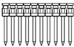 | 6.3 mm(.250") | 6.3 mm(.250") |
 |  | |
| 2.6 mm(.102") | 2.6 mm(.102") |
○Appropriate nail length
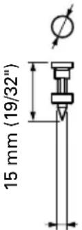
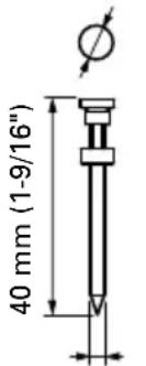
The appropriate nail intrusion length to be drive into concrete is 12 mm – 22 mm (.472" – .866") for nailing wooden materials, and 15 mm – 20 mm (.570" – .787") for nailing thin steel sheet.
Longer nails results in the nails bending.
Select the appropriate length for the materials according to the following table.
| Purpose Type of nail | Nail length d×L d×L | |||
| To nail wood to concrete 2.6 mm × 30 mm(.102" × 1-3/16")2.6 mm × 35 mm(.102" × 1-3/8")2.6 mm × 40 mm(.102" × 1-9/16") | Woodm (.315") countersink.Intrusion depth into concrete | |||
| ConcreteChoose nail to secure approx. 15 mm - 20 mm (.590" - 787")intrusion depth.Example | ||||
| Wood thickness | Appropriatenail length | Intrusion depthinto concrete | ||
| 10 mm (.393") | 30 mm (1-3/16") Approx. 20 mm (.787") | |||
| 15 mm (.590") | 35 mm (1-3/8") Approx. 20 mm (.787") | |||
| 20 mm (.787") | 40 mm (1-9/16") Approx. 20 mm (.787") | |||
| To nail thin steel to concrete 2 | 6 mm × 15 mm(.102" × 19/32")2.6 mm × 20 mm(.102" × 25/32")2.6 mm × 25 mm(.102" × 1") | Thin steel sheet Intrusion depth into concreteConcreteChoose nail to secure approx. 12 mm - 20 mm (.472" - .866")intrusion depth. Intrusion depth into concreteConcreteChoose nail to secure approx. 12 mm - 20 mm (.472" - .866")intrusion depth. | ||
STANDARD ACCESSORIES
(1) Eye protector .... 1
(2) Charger 1
(3) Case 1
(4) Hexagonal bar wrench for M5 screw 1
OPTIONAL ACCESSORIES ...... sold separately
○ Fuel Cell...... Code No. 753-600
○Gas Strip Nailer Lubricant 250 cc (8 oz.) oil feeder ....(Code No. 885-246)
APPLICATIONS
○Attaching a partition runner stopper to concrete
○Attaching wood to concrete
○Attaching a pipe saddle to concrete
CHARGING
Before using the power tool, charge the battery as follows.
1. Insert the battery into the charger
Insert the battery firmly while observing its direction, until it contacts the bottom of the charger (See Fig. 2).
CAUTION
The UC7SD model is the exclusively designed charger. These cannot charge batteries except the specified batteries. It is possible to insert the batteries other than the specified into the charger and some of them may light up the pilot lamps. However, you are requested to exercise utmost caution not to charge batteries other than specified ones because these can not only be charged but also such actions can result in the malfunction of chargers.
2. Connect the charger power cord to the receptacle
Connecting the power cord will turn on the charger (the pilot lamp lights up).
CAUTION
If the pilot lamp does not light up, pull out the power cord from the receptacle and check the battery mounting condition.
About 60 minutes is required to fully charge the battery at a temperature of about 20^ C. The pilot lamp goes off to indicate that the battery is fully charged. The battery charging time becomes longer when a temperature is low or the voltage of the power source is too low. When the pilot lamp does not go off even if more than 120 minutes have elapsed after starting of the charging, stop the charging and contact your HiKOKI AUTHORIZED SERVICE CENTER.
CAUTION
If the battery is heated due to direct sunlight, etc., just after operation, the charger pilot lamp may not light up. At that time, cool the battery first, then start charging.
3. Disconnect the charger power cord from the receptacle
4. Hold the charger firmly and pull out the battery NOTE
After charging, pull out batteries from the charger first, and then keep the batteries properly.
Regarding electric discharge in case of new batteries, etc.
As the internal chemical substance of new batteries and batteries that have not been used for an extended period is not activated, the electric discharge might be low when using them the first and second time. This is a temporary phenomenon, and normal time required for recharging will be restored by recharging the batteries 2 – 3 times.
How to make the batteries perform longer.
(1) Recharge the batteries before they become completely exhausted.
When you feel that the power of the tool becomes weaker, stop using the tool and recharge its battery. If you continue to use the tool and exhaust the electric current, the battery may be damaged and its life will become shorter.
(2) Avoid recharging at high temperatures.
A rechargeable battery will be hot immediately after use. If such a battery is recharged immediately after use, its internal chemical substance will deteriorate, and the battery life will be shortened. Leave the battery and recharge it after it has cooled for a while.
○No flammable gas, liquid or other flammable objects at worksite.
○Use outside or well-ventilated areas. Do not inhale.
○ Keep the tool, fuel cell and battery away from sunshine and from temperature exceeding 50^ C ( 120^ F).
○Keep away from ignition sources. No smoking.
○Clear the area of children or unauthorized personnel.
○Do not store the tool, fuel cell and battery in a cold weather environment. Keep the tool, fuel cell and battery in a warm area until beginning the work.
○If the tool, fuel cell and battery are already cold, bring it in a warm area and allow the tool to warm up before use.
Observe temperature limit of max. 50°C (120°F). Do not expose to an open flame and sparks!
○This tool may not drive completely below when; - at low temperature fuel cell loose the required propellant force, - at high temperature fuel cell overdose.
○Do not use the tool in the rain or where excessive moisture is present.
○This tool is not recommended for use at altitudes above 1,500 m (5000 feet), or in temperature below 0°C (30°F).
1. Fuel cell
To attach the metering valve to a fuel cell:
(1) Separate the metering valve and the cap from the gas cartridge (See Fig. 3 (1)).
(2) Press forward (stem side) and downward on the front side of the metering valve (See Fig. 3 (2)).
(3) Press downward on the rear of the metering valve until it seals (See Fig. 3 (3)).
Check the metering valve:
Press the metering valve stem on fuel cell two or three times against a stationary object and release. If gas is not dispersed, fuel cell is empty. Replace it.
Observe Safety Regulations CAUTION
○If the gas leaks from the metering valve or the gas cartridge after attached the metering valve, replace with the new metering valve.
○Do not attempt to reuse the metering valve. Replace with the new metering valve.
- Battery You must charge the battery before use. The charging method of battery is shown in page 11.
3. Check on safety
CAUTIONS
○Unauthorized persons (including children) must be kept away from the equipment.
○Wear eye protector.
○Check the retaining screws which fix the top cover, etc. for tightness.
Check the tool for defective or rusty parts.
○Check whether or not the push lever works correctly without nails, fuel cell and battery. Also check whether or not any dirt has adhered to the moving parts of the push lever.
○Recheck on operational safety.
BEFORE USE
1. Insert battery into the tool (See Fig. 4)
Do not operate the push lever or trigger while installing the battery.
Make sure the battery indicator light is flashing GREEN (See Fig. 5).
If the battery indicator light is flashing RED, the battery doesn't have enough power and it needs to be charged.
BATTERY INDICATOR LIGHT
- Flashing GREEN: Enough power remaining (The light turns steady during operation).
- Flashing RED: Insufficient power remaining (The light turns steady during operation).
- O FF: The battery is extremely empty. Charge the battery.
Power saving mode
If the tool has not been used for about an one hour with the battery still installed, Power saving mode turns on to minimize unnecessary consumption of battery power. Power saving mode is also activated when the battery power is extremely low or there's an abnormality in the machine so please pay attention to the battery indicator light after deactivating Power saving mode (by removing the battery and reinstall it).
2. Insert fuel cell into the tool
(1) Pulling the latch and open the cell cover (See Fig. 6).
(2) Insert the fuel cell into the tool (See Fig. 7).
(3) Insert the stem of fuel cell into the hole of adaptor (See Fig. 8).
(4) Close the cell cover.
3. Load nails
(1) Insert nail strip into rear of magazine (See Fig. 9).
(2) Slide the nail strip forward in the magazine (See Fig. 10).
(3) Pull the nail feeder (B) back to engage the feeder knob to the nail strip (See Fig. 11).
NOTE
○Use nail strip of more than 10 nails.
The Nailer is now ready to operate.
Removing the nails:
① Pull the feeder knob backward (See Fig. 12). ② Return the feeder knob forward quietly while pushing the nail feeder (B).
③Push the nail stopper. (See Fig. 13)
④Pull out nails from the back of the magazine (See Fig. 14).
CAUTION
To prevent unintentional operation, never touch the trigger or place the top end of the push lever on a work bench on floor. Also, never face the nail outlet toward any part of a person.
○Never use the top cover or housing of this device as a hammer.
○Take precautions to ensure the safety of persons in the vicinity during operation.
○Squeeze the trigger when drive a nail, otherwise the piston can not return correctly.
○Make sure the nailing depth when the temperature is above 40^ C or below 0^ C.
○Hold the Nailer at right angles to the workpiece, otherwise nails may ricochet and cause injury.
1. Nailing procedures
This power tool is equipped with a FULL SEQUENTIAL ACTUATION MECHANISM.
(1) Intermittent nailing
Hold the Nailer at right angles to the workpiece and depress the nail outlet onto the desired point; then pull the trigger to drive a nail in a single shot (See Fig. 15). After nailing once, nailing will not be possible again until the trigger is released and pressed again.
(2) Push lever
When depressing the nail outlet, be sure to fully lift the push lever (See Fig. 15) to release the safety lock. Thus, nails cannot be driven without releasing the safety lock even though the trigger is pulled.
The machine employs a preventive mechanism for unloaded operation.
The machine enters a state where the push lever cannot be pushed up. This takes place when the magazine is not loaded with nails or when the remaining number of nails becomes less than 3.
CAUTION
○Do not drive a nail on another nail.
○Use caution not to throw the push lever tip onto workpiece when the push lever cannot be pushed up.
NOTE
○Under low temperature conditions, the tool sometimes does not operate correctly. Always operate the tool at the appropriate ambient temperature.
2. Clearing a jam
WARNING
○Handle with care to avoid burning yourself, since the nails and nose may become very hot.
If nails are jammed in firing head, remove it, and adjust the nailing in the following order.
①Remove the fuel cell and the battery from the Nailer. (See Fig. 16)
②Lock follower back in magazine and remove fasteners.
③Loosen the knob and lower toward the handle. (See Fig. 17)
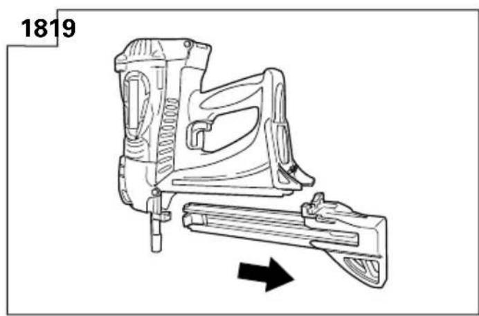
④Pull magazine away from the firing head, and clear jam. (See Fig. 18)
⑤Connect the fuel cell and the battery to the Nailer. ALWAYS WEAR SAFETY GLASSES.
HOW TO USE THE NOSE CAP
WARNING
Before attaching or removing the nose cap, be sure to take your finger off the trigger and remove the fuel cell and battery.
NOTE
Keep the nose cap on when driving nails into slippery materials such as thin steel sheets.
○Remove the nose cap when driving nails into wood.
(1) Removing/Attaching the nose cap
The nose cap is attached simply by pressing it onto the push lever. (See Fig. 19)
To remove, insert a screwdriver or similar into the gap between the nose cap and the push lever and lever off. (See Fig. 20)
INSPECTION AND MAINTENANCE
CAUTION
Be sure to remove the battery and fuel cell during clearing jams, inspection, maintenance and cleaning.
- Inspecting the magazine
①DISCONNECT BATTERY and FUEL CELL.
②Clean the magazine. Remove any plastic chips and concrete dust which may have accumulated in the magazine. Lubricate it with HiKOKI gas strip nailer lubricant.
2. Check on mounting screws for each part
At regular intervals check every part for loose mounting screws. Retighten any loose screws. Operating the equipment with loose screws untightened will incur a hazard.
- Inspecting the push lever
Check if the push lever can slide smoothly. Clean up the sliding area of the push lever and use the provided oil for lubrication from time to time. Lubrication enables smooth sliding and simultaneously serves to prevent the formation of rust.
- Storing (See page 8)
When not in use for an extended period, apply a thin coat of the lubricant to the steel parts to avoid rust.
○Do not store the Nailer in a cold weather environment. Keep the tool in a warm area.
○When not in use, the tool should be stored in a warm and dry place.
Keep out of reach of children.
- Service parts list
CAUTION
Repair, modification and inspection of HiKOKI Power Tools must be carried out by a HiKOKI Authorized Service Center.
This Parts List will be helpful if presented with the tool to the HiKOKI Authorized Service Center when requesting repair or other maintenance.
In the operation and maintenance of power tools, the safety regulations and standards prescribed in each country must be observed.
MODIFICATIONS
HiKOKI Power Tools are constantly being improved and modified to incorporate the latest technological advancements.
Accordingly, some parts may be changed without prior notice.
APPLICABLE LUBRICANTS
Use HiKOKI Gas Nailer lubricant.
Do not use detergent oil or additives.
These lubricants will harm the O-rings and other rubber parts. This will cause the tool malfunction.
Noise Information
Noise characteristic values in accordance with EN 792-13, JUNE, 2000:
The typical A-weighted single-event sound power level
$$ L _ {W A}, 1 \mathrm{s}, \mathrm{d} = 1 0 8 \mathrm{dB} $$
The typical A-weighted single-event emission sound pressure level at work station L_pA1s,d = 99 dB
These values are tool-related characteristic values and do not represent the noise development at the point of use. Noise development at the point of use will for example depend on the working environment, the workpiece, the workpiece support and the number of driving operations, etc.
Depending on the conditions at the workplace and the form of the workpiece, individual noise attenuation measures may need to be carried out, such as placing workpieces on sound-damping supports, preventing workpiece vibration by means of clamping or covering, etc.
In special cases it is necessary to wear hearing protection equipment.
Vibration Information
The typical vibration characteristic value in accordance with EN 792-13, JUNE, 2000: 3.5 m/s ^4
This values is a tool-related characteristic value and does not represent the influence to the hand-arm-system when using the tool. An influence to the hand-arm-system when using the tool will for example depend on the gripping force, the contact pressure force, the working direction, the adjustment of energy supply, the workpiece, the wrokpiece support.
Maintenance chart
| ACTION WHY HOW | ||
| Clean magazine and feeder Prevent mechanism. | a jam. Blow clean daily. | |
| Keep push lever working properly. | Promote operator safety and Blow clean efficient Nailer operation. | daily. |
Operator troubleshooting
| PROBLEM | CHECK METHOD CORRECTION | |
| Nailer operates, but no nail is driven. | Check for a jam. Clear a jam. | |
| Check function of nail feeder. Clean and lubricate. | ||
| Ribbon spring weakened or damaged? | Replace ribbon spring. | |
| Check for proper nails. Use only recommended nails. | ||
| Check if the driver blade piston is down or not. | Push the driver blade with a slotted-head slotted-head screwdriver, and put back the piston to the highest position. | |
| Skipping nails.Intermittent feed. | Check for proper nails. Use only recommended nails. | |
| Check function of nail feeder. Clean and lubricate. | ||
| Ribbon spring weakened or damaged? | Replace ribbon spring. | |
| Nail feeder (B) worn or damaged? | Replace nail feeder (B). | |
| Check for returning of piston. Pull the trigger all the way. | ||
| Too low temperature, warm up fuel cell under 50°C (120°F). | ||
| Check for moving of piston smoothly. | Contact HiKOKI for replacement. | |
| Replace piston ring. | ||
| Replace piston. | ||
| Replace cylinder o-ring. | ||
| Nails jam.Driven nail is bent. | Check for proper nails. Use only recommended nails. | |
| Driver blade worn? Contact HiKOKI for replacement. | ||
| Nail feeder (B) worn or damaged? | Replace nail feeder (B). | |
| The operation of the push lever not smooth. | Push lever bent? Contact HiKOKI for replacement. | |
| Check push lever's moving track, debris? | Contact HiKOKI for replacement. | |
| Fan is working, light indicator shows GREEN yet it doesn't drive a nail or operation unstable. | Check for returning of piston. | Pull the trigger all the way. |
| Too low temperature, warm up fuel cell under 50°C (120°F). | ||
| Check fuel cell, insufficient? | Exchange it with a new fuel cell. | |
| Check spark plug wire, worn out? | Contact HiKOKI for replacement. | |
| Check spark plug, grease or debris? | Contact HiKOKI for replacement. | |
| Check filter, clogged? | Contact HiKOKI for replacement. | |
| Fan does not operate when push lever is pressed. | Magazine empty. | Load more nails in the magazine. |
| Note the color of the light indicator. | If red: charge the battery.If green: Contact HiKOKI for replacement. | |
| Unable to charge battery. | —— | Check the electrical cord. |
- Beton Gas Power Nagler (NC40G)
L_pA, 1s, d = 99 dB
INSPECTION ET MANUTENTION
ATTENTION
L_pA, 1s,d = 99 dB
| ITEM NO. | PART NAME Q'TY | |
| 1 | FLANGED BOLT M5 | 1 |
| 2 | SHAFT RING | 1 |
| 3 | BOLT WASHER D5 | 2 |
| 4 | SHAFT | 1 |
| 5 | TOP COVER | 1 |
| 6 | FILTER ASS'Y | 1 |
| 7 | M4 SCREW | 1 |
| 8 | MOTOR ASS'Y | 1 |
| 9 | RUBBER WASHER | 1 |
| 10 | ROLL PIN D2.5×25 | 1 |
| 11 | MOTOR MOUNT | 1 |
| 12 | MOUNT SLEEVE | 1 |
| 13 | SHAFT WASHER | 1 |
| 14 | MOTOR SPRING | 1 |
| 15 | SPARK PLUG(A) | 1 |
| 16 | HEX.SOCKET BOLT M5×20 | 4 |
| 17 | CYLINDER HEAD | 1 |
| 18 | M4 HEX.SOCKET SCREW | 2 |
| 19 | SHAFT COVER | 1 |
| 20 | WASHER | 1 |
| 21 | O-RING | 1 |
| 22 | NUT | 2 |
| 23 | D4 WASHER | 2 |
| 24 | FAN | 1 |
| 25 | HEX.SOCKET B. M4×16 | 4 |
| 26 | CHAMBER HEAD | 1 |
| 27 | GASKET(A) | 1 |
| 28 | CHAMBER | 1 |
| 29 | PLUNGER O-RING 2 | |
| 30 | CHAMBER LOCK PLATE | 1 |
| 31 | PAN HEAD SCREW M4×6 | 3 |
| 32 | SWITCH PLATE | 1 |
| 33 | PIN | 2 |
| 34 | WIRING PLATE | 1 |
| 35 | ADAPTER | 1 |
| 36 | ROLL PIN D2×8 | 2 |
| 37 | RATCH | 1 |
| 38 | CELL LEVER(A) | 1 |
| 39 | SPRING | 1 |
| 40 | CELL COVER | 1 |
| 41 | CELL RUBBER(A) | 1 |
| 42 | O RING | 1 |
| 43 | C TYPE SPRING 1 | |
| 44 | PISTON RING(A) | 2 |
| 45 | PISTON (H) ASS'Y 1 | |
| 46 | PISTON BUMPER | 1 |
| 47 | CHAMBER STOP RUBBER | 2 |
| 48 | CYLINDER ASS'Y | 1 |
| 49 | HEX. SOCKET HD. BOLT M4×10 | 2 |
| 50 | BAFFER COVER(A) | 1 |
| 51 | REED VALVE | 1 |
| 52 | SEALOCK SCREW M4×6 | 2 |
| 53 | BUFFER PLATE(A) 1 | |
| 54 | MESH | 1 |
| 55 | CONICAL SPRING D4 | 2 |
| 56 | MUFFLER (A) | 1 |
| 57 | CYLINDER | 1 |
| 58 | M5 BOLT | 3 |
| 59 | PUSH LEVER 1 | |
| 60 | NOSE | 1 |
| 61 | D3×8 ROLL PIN | 1 |
| 62 | SPRING (A) | 1 |
| 63 | PUSH LEVER STOPPER | 1 |
| ITEM NO. | PART NAME Q'TY | |
| 64 | ROLL PIN D3×25 1 | |
| 65 | SEALOCK HEX.SOCKET.B. M5 2 | |
| 66 | PUSH LEVER ARM (L) 1 | |
| 67 | PUSH LEVER SPRING 2 | |
| 68 | PUSH LEVER CONNECTOR 1 | |
| 69 | PUSH LEVER ARM (R) 1 | |
| 70 | NAME PLATE 1 | |
| 71 | HOUSING ASS'Y 1 | |
| 72 | ADIABATIC SHEET 1 | |
| 73 | M5 SCREW 4 | |
| 74 | HOUSING 1 | |
| 75 | BRAND PLATE 1 | |
| 76 | TAPPING SCREW D4×20 6 | |
| 77 | HANDLE(B) 1 | |
| 78 | TAPPING SCREW D4×45 1 | |
| 79 | HEX. SOCKET HD. BOLT M5×16 (SEALOCK) | 1 |
| 80 | WASHER | 1 |
| 81 | SWITCH MOUNT (B) | 1 |
| 82 | SWITCH ARM | 1 |
| 83 | LEAD WIRE ASS'Y (B) | 1 |
| 84 | SPRING | 1 |
| 85 | SWITCH LEVER (B) | 1 |
| 86 | TENSION PLATE (C) | 1 |
| 87 | TRUSS HEAD TAPPING SCREW M3 | 1 |
| 88 | PRISM | 1 |
| 89 | TRIGGER SPRING (A) | 1 |
| 90 | TRIGGER | 1 |
| 91 | ROLL PIN D2.5×10 | 1 |
| 92 | CHAMBER LOCK BAR 1 | |
| 93 | LOCK BAR SPRING | 1 |
| 94 | CONTROLLER ASS'Y | 1 |
| 95 | TAP.SCREW D4 W/F | 2 |
| 96 | WIRING COVER | 1 |
| 97 | D4 FLAT TAPPING SCREW | 1 |
| 98 | HANDLE (A) | 1 |
| 99 | BATTERY ASS' Y | 1 |
| 100 | DUST COVER 1 | |
| 101 | WASHER | 2 |
| 102 | TAPPING SCREW D4×12 2 | |
| 103 | WASHER (B) | 1 |
| 104 | SHAFT (B) | 1 |
| 105 | TAPPING SCREW (W/FLANGE) D4×14 | 1 |
| 106 | WASHER | 1 |
| 107 | NAIL STOPPER | 1 |
| 108 | SPRING (C) 1 | |
| 109 | SQ.NUT M6 | 1 |
| 110 | MAGAZINE 1 | |
| 111 | MAGAZINE COVER | 1 |
| 112 | SHAFT(C) | 1 |
| 113 | WASHER | 1 |
| 114 | SPRING WASHER M5 1 | |
| 115 | KNOB | 1 |
| 116 | HEX.SOCKET BUTTON BOLT M6 | 1 |
| 117 | RIBBON SPRING ASS'Y | 1 |
| 118 | PIN D3×20 | 1 |
| 119 | NAIL FEEDER (B) | 1 |
| 120 | NAIL FEEDER (A) 1 | |
| 121 | SPRING (B) 1 | |
| 122 | O-RING | 1 |
| 501 | CHARGER (MODEL UC7SD) | 1 |
| 502 | PROTECTIVE GLASSES | 1 |
| 503 | HEX.BAR WRENCH 4MM | 1 |
| 504 | CASE | 1 |

natural_image
Line drawing of a quill pen in an inkwell (no text or symbols)
natural_image
Line drawing of a quill pen with inkwell (no text or symbols)
natural_image
Line drawing of a quill pen in an inkwell (no text or symbols)
natural_image
Symbol of a trash bin crossed with no visible text or labelsEnglish
Only for EU countries
Do not dispose of electric tools together with household waste material!
In observance of European Directive 2002/96/EC on waste electrical and electronic equipment and its implementation in accordance with national law, electric tools that have reached the end of their life must be collected separately and returned to an environmentally compatible recycling facility.
Deutsch
Nur für EU-Länder


- GENERAL OPERATIONAL PRECAUTIONS
- PRECAUTIONS ON USING GAS CONCRETE NAILER
- Explosion and fire hazard.
- Always wear eye protection (protective goggles).
- Protect your ears and head.
- Use outside or well-ventilated areas.
- Pay attention to those working close to you.
- Never point the nail outlet towards people.
- Before using the power tool, check the push lever.
- Use specified nails only.
- Be careful when connecting the battery.
- Do not carelessly place your finger on the trigger.
- Press the nail outlet firmly against the material to be nailed.
- Keep hands and feet away from the firing head when using.
- Do not touch around the exhaust outlet.
- Beware of the tool's kickback.
- Take care when nailing the corners of workpiece.
- Simultaneous nailing on both sides of the same wall is dangerous.
- Do not use the power tool on scaffoldings, ladders.
- Disconnect the battery and fuel cell and take out any nails left in the magazine after use.
- When removing a nail which has become stuck, make sure to first of all disconnect the battery and fuel cell.
- The operating environment for this device is between 0°C (32°F) and 40°C (104°F) so ensure use within this temperature range. The device may fail to operate below 0°C (32°F) or above 40°C (104°F).
- Always charge the battery at an ambient temperature of 0–40°C.
- Do not use the charger continuously.
- Do not allow foreign matter to enter the hole for connecting the rechargeable battery.
- Never disassemble the rechargeable battery or charger.
- Never short-circuit the rechargeable battery.
- Do not dispose of the battery in fire.
- Using an exhausted battery will damage the charger.
- Bring the battery to the shop from which it was purchased as soon as the post-charging battery life becomes too short for practical use.
- Do not insert objects into the air ventilation slots of the charger.
- Do not inhale its contents.
- Expanding gases cause low temperatures.
- Fluid gases might cause injuries when getting in touch with skin or eyes.
- Fuel cells.
- Transportation/Storage.
- SPECIFICATIONS
- NAIL SELECTION
- ○Appropriate nail length
- STANDARD ACCESSORIES
- OPTIONAL ACCESSORIES ...... sold separately
- APPLICATIONS
- CHARGING
- Insert the battery into the charger
- CAUTION
- Connect the charger power cord to the receptacle
- Disconnect the charger power cord from the receptacle
- Hold the charger firmly and pull out the battery NOTE
- Regarding electric discharge in case of new batteries, etc.
- How to make the batteries perform longer.
- Fuel cell
- Observe Safety Regulations CAUTION
- Check on safety
- CAUTIONS
- BEFORE USE
- Insert battery into the tool (See Fig. 4)
- BATTERY INDICATOR LIGHT
- Power saving mode
- Insert fuel cell into the tool
- Load nails
- NOTE
- Removing the nails:
- Nailing procedures
- Clearing a jam
- WARNING
- HOW TO USE THE NOSE CAP
- INSPECTION AND MAINTENANCE
- MODIFICATIONS
- APPLICABLE LUBRICANTS
- Noise Information
- Vibration Information
- INSPECTION ET MANUTENTION
- ATTENTION
- English
- Deutsch
Brand : HiKOKI
Model : NC40G
Category : Stapler