
NV100H - Stapler HiKOKI - Free user manual and instructions
Find the device manual for free NV100H HiKOKI in PDF.
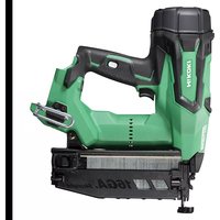
| Product Type | Pneumatic coil nailer |
| Brand | HiKOKI |
| Model | NV100H |
| Dimensions (L × H × W) | 280 mm × 338 mm × 132 mm |
| Weight | 2.7 kg |
| Recommended air pressure | 12 to 23 bar |
| Nail type | Wire-collated coil nails |
| Nail length | 50 to 100 mm |
| Nail diameter | 2.5 to 3.8 mm |
| Magazine capacity | 150 to 300 nails (1 coil) |
| Hose inner diameter | 5 to 6 mm |
| Nailing mode | Intermittent and continuous |
| Depth adjustment | Yes, by adjustment dial |
| Trigger lock | Yes, lock lever |
| Sound pressure level | LpA = 91.6 dB(A), uncertainty K = 2.5 dB(A) |
| Vibration level | 5.3 m/s², uncertainty K = 1.5 m/s² |
| Recommended lubrication | SHELL TONNA oil or equivalent |
| Included accessories | Safety goggles, oil can, nose cap |
| Applications | Wood, framing, crates, pallets, mobile homes |
| Maintenance | Daily lubrication, regular cleaning |
Frequently Asked Questions - NV100H HiKOKI
User questions about NV100H HiKOKI
0 question about this device. Answer the ones you know or ask your own.
Ask a new question about this device
Download the instructions for your Stapler in PDF format for free! Find your manual NV100H - HiKOKI and take your electronic device back in hand. On this page are published all the documents necessary for the use of your device. NV100H by HiKOKI.
USER MANUAL NV100H HiKOKI
Read through carefully and understand these instructions before use. Diese Anleitung vor Benutzung des Werkzeugs sorgfältig durchlesen und verstehen. Lire soigneusement et bien assimiler ces instructions avant usage. Prima dell'uso leggere attentamente e comprendere queste instruzioni. Deze gebruiksaanwijzing s.v.p. voor gebruik zorgvuldig doorlezen. Leer cuidadosamente y comprender estas instrucciones antes del uso. Antes de usar, leia com cuidado para assimilar estas instruções.
Handling instructions Bedienungsanleitung Mode d'emploi Istruzioni per l'uso Gebruiksaanwijzing Instrucciones de manejo Instruções de uso
1
2

3
4
5


15 16

17 18


19 20

21 22

| English Deutsch Français Italiano | ||||
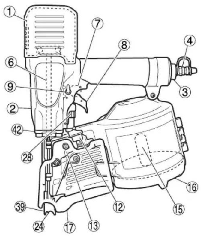
| 1 | Exhaust cover Entlüftungsdeckel Couvercle d'échappement Copertura scarico | |||
| 2 | Body Gerätekörper Corps Corpo | |||
| 3 | Cap Kappe Capuchon Cappuccio | |||
| 4 | Air plug Schnellkupplung Bouchon d'air Tappo aria | |||
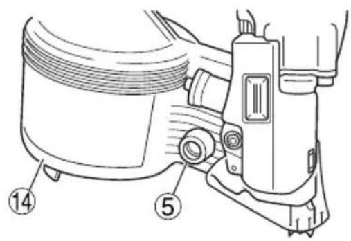
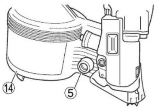
| 5 | Nose cap | Nasenkappe | Capuchon de museau | Tappo del naso |
| 6 | Piston | Kolben | Joint torique du piston | Pistone |
| 7 | Valve | Ventil | Valve | Valvola |
| 8 | Trigger | Abzug | Gâchette | Grilletto |
| 9 | Lock lever | Sperrhebel | Levier de verrouillage | Leva di blocco |
| 10 | Lock position | Sperrposition | Position de verrouillage | Posizione di blocco |
| 11 | Free position | Freigabeposition | Position libre | Posizione libera |
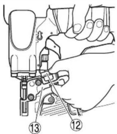
| 12 | Knob | Knopf | Bouton | Manopola |
| 13 | Nail guide | Nagelführung | Guide-clous | Guida dei chiodi |
| 14 | Magazine | Magazin Magasin | Contenitore | |
| 15 | Nail holder | Nagelhalter | Porte-clous | Portachiodi |
| 16 | Magazine cover | Magazinabdeckung | Couvercle du magasin | Coperchio del contenitore |
| 17 | Dust cover | Staubkappe | Couvercle à poussière | Coperchio antipolvere |
| 18 | For 50 mm | Für 50 mm | Pour 50 mm | Per 50 mm |
| 19 | For 57 mm | Für 57 mm | Pour 57 mm | Per 57 mm |
| 20 | For 65, 75 mm Für 65, 75 mm Pour 65, 75 mm Per 65, 75 mm | |||
| 21 | For 90, 100 mm | Für 90, 100 mm | Pour 90, 100 mm Per 90, 100 mm | |
| 22 | Nails | Nägel | Clous | Chiodi |
| 23 | First nail | Erster Nagel | Premier clou | Primo chiodo |
| 24 | Outlet Mündung | Sortie | Uscita | |
| 25 | Pawl (1) | Klinke (1) | Cliquet (1) | Dente (1) |
| 26 | Pawl (2) Klinke (2) | Cliquet (2) | Dente (2) | |
| 27 | Guide slot | Führungsschlitz | Fente-guide | Fessura di guida |
| 28 | Adjuster | Einsteller | Ajusteur | Regolatore |
| 29 | Shallow | Flach | En superficie | Laggero |
| 30 | Deep | Tief | En profondeur Profondo | |
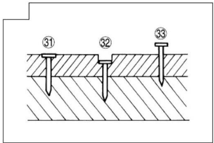
| 31 | Flush | Normal | Normal | Normale |
| 32 | Too deep | Zu tief | Trop profond | Troppo profondo |
| 33 | Too shallow | Zu flach | Trop en superficie | Troppo leggero |
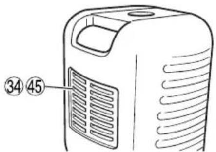
| 34 | Exhaust vent | Abluftöffnung | Event d'échappement | Apertura di scarico |
| 35 | Remove dust | Staubfänger | Dépoussiéreur | Rimuovere la polvere |
| 36 | Hammer | Hammer | Marteau | Martello |
| 37 | Rod Stange | Tige | Asta | |
| 38 | Slotted screwdriver | Flacher Schraubenzieher | Tournevis plat | Cacciavite a fessura |
| 39 | Push lever | Druckhebel | Levier -poussoir | Leva a pressione |
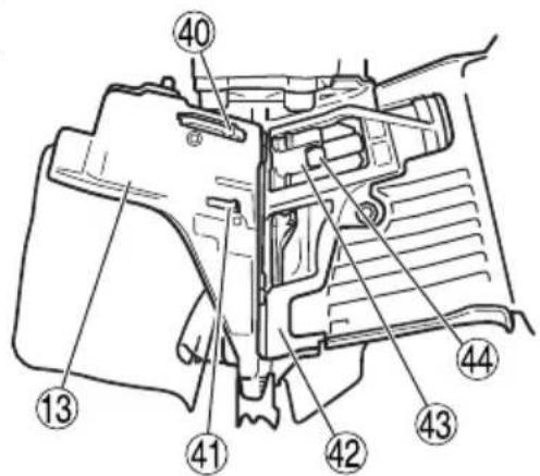
| 40 | Nail stopper (A) | Nagelstopper (A) | Butée des clous (A) | Fermo dei chiodi (A) |
| 41 | Nail stopper (B) | Nagelstopper (B) | Butée des clous (B) | Fermo dei chiodi (B) |
| 42 | Tail cover | Hinterer Deckel | Couvercle de la queue | Coperchio di coda |
| 43 | Feeder | Zubringer | Chargeur | Alimentatore |
| 44 | Shaft Welle | Arbre | Asta | |
| 45 | Muffler | Schalldämpfer | Pot d'échappement | Silenziatore |
| 46 | Hole | Loch | Trou | Foro |
| 47 | Protruding section (inside) | Vorstehender Teil (innen) | Section saillante (intérieur) | Sezione sporgente (interno) |
| Nederlands Español | Português | ||
| 1 | Uitlaatdeksel Cubierta de escape | Tampa de escape | |
| 2 | Behuizing Cuerpo Corpo | ||
| 3 | Kap | Tapa | Tampa |
| 4 | Luchtplug Toma de aire Obturador de ar | ||
| 5 | Neuskap Tapa de la punta Tampa do nariz | ||
| 6 | Zuiger Pistón Pistão | ||
| 7 | Schuif Válvula Válvula | ||
| 8 | Trekker Gatillo Gatilho | ||
| 9 | Veiligheidshendel Palanca | de bloqueo Alavanca de bloqueio | |
| 10 | Vergrendelde Positie | Posición de bloqueo | Posição de bloqueio |
| 11 | Vrije Positie | Posición libre | Posição livre |
| 12 | Knop | Perilla Botão | |
| 13 | Spijkergeleider | Guía de puntas | Guia de prego |
| 14 | Magazijn | Cargador | Carregador |
| 15 | Spijkerhouder | Soporte de puntas | Porta-pregos |
| 16 | Magazijnklep | Cubierta del cargador | Tampa do carregador |
| 17 | Stofkap | Tapón guardapolvo | Tampa anti-poeira |
| 18 | Voor 50 mm | Para 50 mm | Para 50 mm |
| 19 | Voor 57 mm | Para 57 mm | Para 57 mm |
| 20 | Voor 65, 75 mm | Para 65, 75 mm | Para 65, 75 mm |
| 21 | Voor 90, 100 mm | Para 90, 100 mm | Para 90, 100 mm |
| 22 | Spijkers | Puntas | Pregos |
| 23 | Eerste spijker | Primera punta | Primeiro prego |
| 24 | Uitlaat Salida Saída | ||
| 25 | Pal (1) | Uña (1) | Lingueta (1) |
| 26 | Pal (2) Uña (2) | Lingueta (2) | |
| 27 | Geleidesleuf | Ranura guía | Ranhura de guia |
| 28 | Instelling | Ajustador | Regulador |
| 29 | Ondiep Poca profundidad Raso | ||
| 30 | Diep Profundidad profunda | Profundo | |
| 31 | Normaal | Normal Nivelado | |
| 32 | Te diep | Demasiado profundo | Muito profundo |
| 33 | Te ondiep | Demasiado poco profundo | Muito raso |
| 34 | Uitlaat Salida del aire de escape | Respirador de descarga | |
| 35 | Verwijder stof | Retirar polvo | Remover poeira |
| 36 | Hamer | Martillo Martelo | |
| 37 | Stang | Varilla | Haste |
| 38 | Schroevendraaier met inkeping | Destornillador de punta plana | Chave de fendas ranhurada |
| 39 | Drukhendel | Palanca de empuje | Alavanca de pressão |
| 40 | Spijkerstopper (A) | Retén de puntas (A) Batente | de preto (A) |
| 41 | Spijkerstopper (B) | Retén de puntas (B) Batente | de preto (B) |
| 42 | Afdekking van het achterdeel | Tapa de parte trasera | Tampa da cauda |
| 43 | Toevoer | Alimentador | Alimentador |
| 44 | As | Eje | Eixo |
| 45 | Demper | Silenciador | Silenciador |
| 46 | Gat | Orificio | Orifício |
| 47 | Uitstekend gedeelte (binnen) | Sección sobresaliente (dentro) | Secção protuberante (interior) |
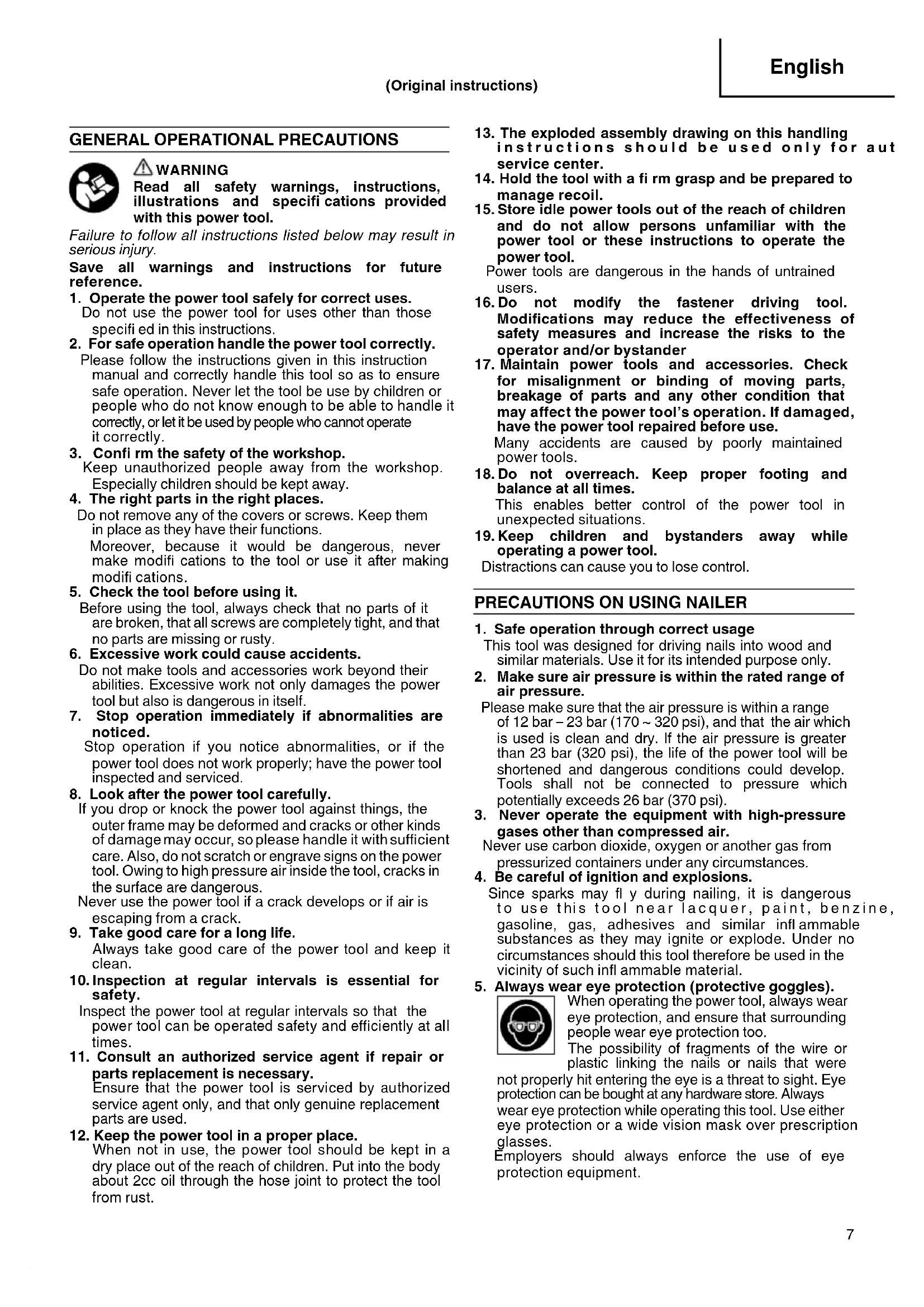
GENERAL OPERATIONAL PRECAUTIONS

WARNING
Read all safety warnings, instructions, illustrations and specifications provided with this power tool.
Failure to follow all instructions listed below may result in serious injury.
Save all warnings and instructions for future reference.
- Operate the power tool safely for correct uses.
Do not use the power tool for uses other than those specified in this instructions.
- For safe operation handle the power tool correctly.
Please follow the instructions given in this instruction manual and correctly handle this tool so as to ensure safe operation. Never let the tool be use by children or people who do not know enough to be able to handle it correctly, or let it be used by people who cannot operate it correctly.
- Confi rm the safety of the workshop.
Keep unauthorized people away from the workshop. Especially children should be kept away.
- The right parts in the right places.
Do not remove any of the covers or screws. Keep them in place as they have their functions.
Moreover, because it would be dangerous, never make modifi cations to the tool or use it after making modifi cations.
- Check the tool before using it.
Before using the tool, always check that no parts of it are broken, that all screws are completely tight, and that no parts are missing or rusty.
- Excessive work could cause accidents.
Do not make tools and accessories work beyond their abilities. Excessive work not only damages the power tool but also is dangerous in itself.
- Stop operation immediately if abnormalities are noticed.
Stop operation if you notice abnormalities, or if the power tool does not work properly; have the power tool inspected and serviced.
- Look after the power tool carefully.
If you drop or knock the power tool against things, the outer frame may be deformed and cracks or other kinds of damage may occur, so please handle it with sufficient care. Also, do not scratch or engrave signs on the power tool. Owing to high pressure air inside the tool, cracks in the surface are dangerous.
Never use the power tool if a crack develops or if air is escaping from a crack.
- Take good care for a long life.
Always take good care of the power tool and keep it clean.
- Inspection at regular intervals is essential for safety.
Inspect the power tool at regular intervals so that the power tool can be operated safety and efficiently at all times.
- Consult an authorized service agent if repair or parts replacement is necessary.
Ensure that the power tool is serviced by authorized service agent only, and that only genuine replacement parts are used.
- Keep the power tool in a proper place.
When not in use, the power tool should be kept in a dry place out of the reach of children. Put into the body about 2cc oil through the hose joint to protect the tool from rust.
-
The exploded assembly drawing on this handling instructions should be used only for aut service center.
-
Hold the tool with a fi rm grasp and be prepared to manage recoil.
-
Store idle power tools out of the reach of children and do not allow persons unfamiliar with the power tool or these instructions to operate the power tool.
Power tools are dangerous in the hands of untrained users.
-
Do not modify the fastener driving tool. Modifications may reduce the effectiveness of safety measures and increase the risks to the operator and/or bystander
-
Maintain power tools and accessories. Check for misalignment or binding of moving parts, breakage of parts and any other condition that may affect the power tool's operation. If damaged, have the power tool repaired before use.
Many accidents are caused by poorly maintained power tools.
- Do not overreach. Keep proper footing and balance at all times.
This enables better control of the power tool in unexpected situations.
- Keep children and bystanders away while operating a power tool.
Distractions can cause you to lose control.
PRECAUTIONS ON USING NAILER
- Safe operation through correct usage
This tool was designed for driving nails into wood and similar materials. Use it for its intended purpose only.
- Make sure air pressure is within the rated range of air pressure.
Please make sure that the air pressure is within a range of 12 bar – 23 bar (170 \~ 320 psi), and that the air which is used is clean and dry. If the air pressure is greater than 23 bar (320 psi), the life of the power tool will be shortened and dangerous conditions could develop. Tools shall not be connected to pressure which potentially exceeds 26 bar (370 psi).
- Never operate the equipment with high-pressure gases other than compressed air.
Never use carbon dioxide, oxygen or another gas from pressurized containers under any circumstances.
- Be careful of ignition and explosions.
Since sparks may fly during nailing, it is dangerous to use this tool near lacquer, paint, benzine, gasoline, gas, adhesives and similar infl ammable substances as they may ignite or explode. Under no circumstances should this tool therefore be used in the vicinity of such infl ammable material.
- Always wear eye protection (protective goggles).

When operating the power tool, always wear eye protection, and ensure that surrounding people wear eye protection too.
The possibility of fragments of the wire or plastic linking the nails or nails that were
not properly hit entering the eye is a threat to sight. Eye protection can be bought at any hardware store. Always wear eye protection while operating this tool. Use either eye protection or a wide vision mask over prescription glasses.
Employers should always enforce the use of eye protection equipment.
6. Protect your ears and head.

When engaged in nailing work please wear ear mufflers and head protection. Also, depending on condition, ensure that 14 surrounding people also wear ear mufflers and head protection. Unprotected exposure
to high noise levels can cause permanent, disabling, hearing loss and other problems such as tinnitus (ringing, buzzing, whistling or humming in the ears).
Risk assessment and implementation of appropriate controls for these hazards are essential.
Appropriate controls to reduce the risk may include actions such as damping materials to prevent workpieces from “ringing”.
Operate and maintain the tool as recommended in these instructions, to prevent an unnecessary increase in noise levels.
7. Pay attention to those working close to you.
It would be very dangerous if nails that were not properly driven in should hit other people. Therefore, always pay attention to the safety of the people around you when using this tool. Always make sure that nobody's body, hands or feet are close to the nail outlet.
8. Never point the nail outlet towards people.
Always assume the tool contains fasteners.
If the nail outlet is pointed towards people, serious accidents may be caused if you mistakenly discharge the tool. When connecting and disconnecting the hose, during nail loading or similar operations, be sure the nail outlet is not pointed towards anyone (including yourself). Even when no nails are loaded at all, it is dangerous to discharge the tool while pointing it at someone, so never attempt to do so. No horseplay. Respect the tool as a working implement.
9. Before using the power tool, check the push lever.
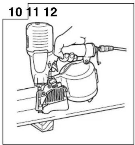
You may rest the tool on a level surface as shown in Fig. 10.
Be sure not to apply the force downward onto the tool to the extent that the push lever is engaged.
Before using the power tool make sure to check that the push lever and valve operate properly. Without nails loaded into the power tool, connect the hose and check the following. If the sound of operation occurs this indicates a fault, so in such a case do not use the power tool until it has been inspected and repaired.
○ If merely pulling the trigger causes operating sound of drive bit movement occur, the power tool is faulty.
☐ If merely pushing the push lever against the material to be nailed causes the sound of drive bit movement to occur, the power tool is faulty. Furthermore, with regard to the push lever, please note that it must never be modified or removed.
10. Use specifi ed nails only.
Never use nails other than those specified and described in these instructions.
11. Do not modify the fastener driving tool.
Modifications may reduce the effectiveness of safety measures and increase the risks to the operator and/or bystander.
12. Be careful when connecting the hose.
When connecting the hose and loading nails in order not to fire the tool by mistake, make sure of the following.
○ Do not touch the trigger.
○ Do not allow the firing head to contact with any surface.
○ Keep the firing head down.
Strictly observe the above instructions, and always make sure that no part of the body, hands or legs is ever in front of the nail outlet.
-
Be careful when handling fasteners, especially when loading and unloading, as the fasteners have sharp points which could cause injury.
-
Do not carelessly place your finger on the trigger. Do not place your finger on the trigger except when actually nailing. If you carry this tool or hand it to someone while having your finger on the trigger, you may inadvertently discharge a nail and thus cause an accident.
15. Completely Close the nail guide and do not open it during operation.
If nailing is attempted when the nail guide is open, nails will not be driven into the timber, and there is a risk of dangerous discharge.
16. Press the nail outlet firmly against the material to be nailed.
When driving in nails, press the nail outlet firmly against the material to be nailed. If the outlet is not applied properly, the nails may rebound.
17. Keep hands and feet away from the firing head when using.
It is very dangerous for a nail to hit the hands or feet by mistake.
18. During operation, debris from workpiece and fastening/collation system may be discharged.
19. Beware of the tool's kickback
Do not approach the top of the tool with your head etc. during operation. This is dangerous because the tool may recoil violently if the nail currently being driven in comes into contact with a previous nail or a knot in the wood.
20. Take care when nailing thin boards or the corners of wood.
When nailing thin boards, the nails may pass right through, as may also be the case when no corners of wood due to deviation of the nails. In such cases, always make sure that there is no one (and nobody's hands or feet; etc.) behind the thin board or next to the wood you are going to nail.
21. Simultaneous nailing on both sides of the same wall is dangerous
Under no circumstances should nailing be performed on both sides of a wall at the same time. This would be very dangerous since the nails might pass through the wall and thus cause injuries.
22. Do not use the power tool on scaffoldings, ladders.
The power tool shall not be used for specific application for example:
- when changing one driving location to another involves the use of scaff orldings, stairs, ladders or ladder alike constructions, e.g. roof laths,
– closing boxes or crates, - fitting transportation safety systems e.g. on vehicles and wagons
23. Do not disconnect the hose with your finger on the trigger.
If you disconnect the hose with your finger on the trigger, the next time the hose is connected, there is a danger that the power tool will fire a nail spontaneously, or operate incorrectly.
24. Disconnect the hose and take out any nails left in the magazine after use.
Disconnect tool from air before doing tool maintenance, cleaning a jammed fastener, leaving work area, moving tool to another location, or after use. It is very dangerous for a nail to be fi red by mistake.
- When removing a nail which has become stuck, make sure to first of all disconnect the hose and release compressed air.
When removing a nail which has become stuck in the nail outlet, first of all make sure to disconnect the hose and release compressed air inside the power tool. Accidental firing of the nail could be very dangerous.
-
To avoid hazards caused by falling nails, never open the magazine with the device facing downward while loading nails.
-
A female plug (air socket) should not be used in the body.
If a female plug is installed in the body, the compressed air sometimes can not be drawn when the hose is disconnected so avoid this.
The tool and air supply hose must have a hose coupling such that all pressure is removed from the tool when the coupling joint is disconnected.
- While using a tool, the operator shall adopt a suitable but ergonomic posture.
Maintain secure footing and avoid awkward or off-balanced postures.
- If the operator experiences symptoms such as persistent or recurring discomfort, pain, throbbing, aching, tingling, numbness, burning sensation, or stiffness, do not ignore these warning signs.
The operator shall consult a qualified health professional regarding overall activities.
- Long time continuous and repetitive work may lead to muscular-skeletal disorders.
Do not keep working with a same posture or by applying excessive force for a long time.
And take some rest regularly and especially when you feel tired.
- Slips, trips and falls are major causes of workplace injury.
Be aware of slippery surfaces caused by use of the tool and also of trip hazards caused by the airline hose.
- Proceed with additional care in unfamiliar surroundings.
Hidden hazards may exist, such as electricity or other utility lines.
-
Make sure there are no electrical cables, gas pipes etc. that could cause a hazard if damaged by use of the tool.
-
Risk assessment should include dust created by the use of the tool and the potential for disturbing existing dust.
-
Direct the exhaust so as to minimize disturbance of dust in a dust filled environment.
-
Where dust or exhaust hazards are created, the priority shall be to control them at the point of emission.
-
Information to conduct a risk assessment of these hazards and implementation of appropriate controls is essential.
-
Exposure to vibration can cause disabling damage to the nerves and blood supply of the hands and arms.
-
Wear warm clothing when working in cold conditions, keep your hands warm and dry.
-
If you experience numbness, tingling, pain or whitening of the skin in your fingers or hands, seek medical advice from a qualified occupational health professional regarding overall activities.
-
Operate and maintain the tool as recommended in these instructions, to prevent an unnecessary increase in vibration levels.
-
Hold the tool with a light, but safe, grip because the risk from vibration is generally greater when the grip force is higher.
-
Do not remove the dust cover.
Never operate with the dust cover removed in order to avoid the danger of breakage of the wire or plastic retaining the nails or missed-fired nails flying about.
- Disconnect the air hose before operating the nose switch lever.
Be sure to disconnect the air hose before operating the nose switch lever. Otherwise, you run the risk of accidentally firing nails.
- When attaching and detaching the nose cap, disconnect the hose.
When attaching the accessory nose cap to the tip of the push lever and when detaching it, make sure to disconnect the hose beforehand. It is very dangerous for a nail to be fired by mistake.
- Use a compressor and an air hose intended for high-pressure nailers.
This nailer is designed to operate with air pressure higher than that for general nailers. Therefore, use a compressor and an air hose intended for use with a high-pressure nailer. The main unit of this nailer, its air plug, and the air socket used to connect the compressor and air hose are exclusively designed for use with high-pressure parts, and cannot be connected to standard-pressure parts. Do not modify the air plug and air socket. Using other parts may result in an accident.
SPECIFICATIONS
| Type of power Piston reciprocating | |
| Air pressure (Gauge) 12 – 23 bar (170 – 320 psi) | |
| Applicable nails ref. Fig. | |
| Amount of loadable nails 150 – 300 nails (1 coil) | |
| Size 280 mm (L) × 338 mm (H) × 132 mm (W) | (11” × 13-5/16” × 5-3/16”) |
| Weight 2.7 kg (5.9 lbs) | |
| Nail-feeding method Piston reciprocation | |
| Hose (inside diam.) 5 – 6 mm (13/64” – 15/64”) | |
NAIL SELECTION
Wire collated nails can be driven with this tool.
Choose a suitable nail from Fig. Nails which are not shown in Fig. can not be driven with this tool. Nails are linked and rolled.
| Wire-collatd coil nails | |
| Min. Max. | |
| 6 mm (.236") 50 mm (2") 2.5 mm (.099") | 7.9 mm (.311") 100 mm (4") 3.8 mm (.148") |
Dimensions of nails
STANDARD ACCESSORIES
(1) Eye protector 1
(2) Oiler 1
(3) Nose cap 1
OPTIONAL ACCESSORY
○ Single Sequential Actuation Mechanism Kit
(Sequential Fire Parts Set, Single Shot Parts)
With the sequential fire parts, the nail is driven by squeezing the trigger after pushing down the push lever.
By installing these parts, driving nails into improper positions and unexpected fi ring of nails caused by accidental operation of the push lever can be prevented.
APPLICATIONS
○ Construction wooden works such as floor and wall framing, roof decking and subfl ooring.
○ Mobile and modular home construction.
○ Making wooden boxes, palletes, and drums.
○ Packing operations in manufacturing plants, and other types of packing and crating work in general.
Use an air hose designed for high-pressure operation. Be sure to use the hose provided with minimum 5 mm (13/64") inside diameter.
NOTE
The air supply hoses must have a minimum working pressure rating of 29.4 bar (420 psi).
2. Check on safety
CAUTION
- Unauthorized persons (including children) must be kept away from the equipment.
○ Wear eye protector.
- Check the retaining screws which fix the exhaust cover, etc. for tightness.
Check the nailer for air leaks and defective or rusty parts.
☐ Check whether or not the push lever works correctly. Also check whether or not any dirt has adhered to the moving parts of the push lever.
○ Recheck on operational safety.
BEFORE USE
1. Check the air pressure
CAUTION
Use a compressor designed for high-pressure operation. The air pressure must be constantly maintained at 12 – 23 bar (170 – 320 psi).
Adjust the air pressure between 12 to 23 bar (170 - 320 psi) according to the diameters and length of nails and hardness of the wood being nailed. Pay special attention to the output pressure, capacity, and piping on the air compressor, so that air pressure does not exceed the specified limit. Note that excessive pressure may affect overall performance, service life, and safety.
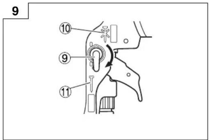
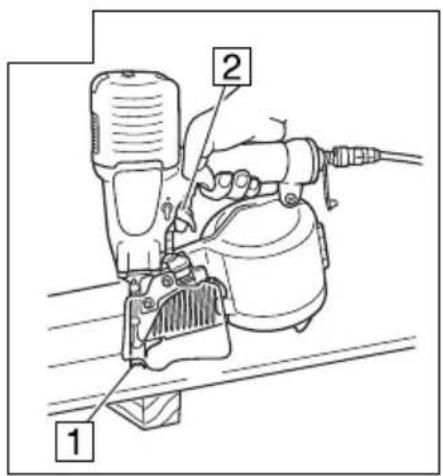
2. Lock mechanism of the trigger
This device has a lock mechanism to prevent the trigger from pulling.
Set the lock lever to "Lock" position to lock the trigger in place.
To drive a nail, turn the lock lever to the "Free" position. When not driving nails set the lever to the "Lock" position (Fig. 2).
CAUTION
Keep the trigger locked at all times except when driving nails.
3. Lubrication
(1) Be sure to lubricate this nailer at least twice a day. To lubricate, pour 10 to 15 drops of oil into the air plug only before and after using this nailer. The oil applied before use lubricates this nailer; the oil applied after use prevents rust.
(2) It is recommended using the recommended oil (SHELL TONNA). Other applicable oils are listed. Never mix two or more types of different oils.
4. Load Nails
(1) Grip the nail guide and knob with finger.
Press the knob down and swing the nail guide open.
And open the magazine cover (Fig. 3).
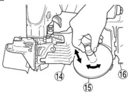
(2) Adjust the position of the nail holder according to the nail length (Fig. 4).
The nail will not feed smoothly if the nail holder is not correctly adjusted (Fig. 5).
a. Turn the nail holder about 90 degrees counterclockwise.
b. Slide in vertical direction possible.
Lift or lower the nail holder to accept different length nails.
c. Adjust the plate to the nail length reference points on the magazine cover and turn the nail holder 90 degrees clockwise until you hear "click".
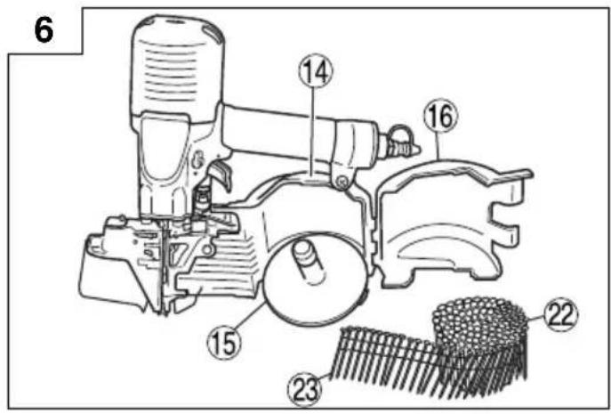
(3) Place the nail coil into the magazine.
Uncoil enough nails to reach the driving hole (Fig. 6).
Insert the first nail into the driving hole and the second nail between the two pawls of the feeder.
Fit the nail head in the guide slot (Fig. 7).
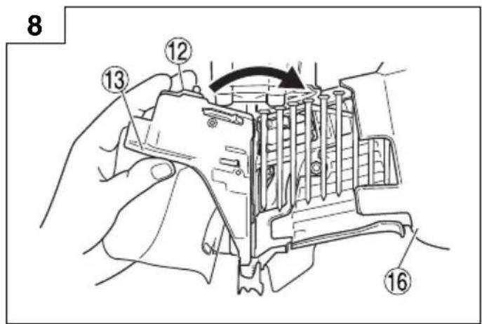
(4) Close the magazine cover first and swing the nail guide closed (Fig. 8).
(5) Lock the knob correctly.
NOTE
Be careful not to deform the collated wires and not to disengage the nails with the guide surface.
Otherwise, the nail guide will not close correctly.
CAUTION
To prevent unintentional operation, never touch the trigger or place the top end of the push lever on a work bench or floor. Also, never face the nail outlet toward any part of a person.
NOTE
Before loading the nails in the magazine, position the nail holder according to the length of the nail. If the nail holder position is not adjusted properly, nail feed may jam. If the cover is forcibly closed without adjusting the position of the nail holder, the nail holder may be damaged.
Do not use the body or any portion of the tool as a hammer as nails may be discharged unexpectedly or the tool may become damaged and serious injury could occur.
- Take precautions to ensure the safety of persons in the vicinity during operation.
- Ensure tool is always safely engaged on the workpiece and cannot slip.
○ Never carry a pneumatic tool by its hose.
○ Never drag a pneumatic tool by its hose.
1. Set the lock lever to "Free" position
Turn the lock lever and align it with the "Free" position (Fig. 9).
2. How to drive nails
This device is equipped with a mechanism allowing “intermittent operation” or “continuous operation” for most effective use according to the type material the nails will be driven into.
(1) Intermittent operation
Intermittent operation nail driving is used when the fi nished appearance is important and when driving a nail in a particular spot. ① Press the push-lever up against the spot where you will drive the nail. ② Drive the nails one at a time by pulling the trigger (Fig. 11).
NOTE
Use "intermittent operation" when you are aiming at a particular spot to drive the nail.
(2) Continuous operation
To drive nails with contact drive: ① First, pull the trigger. ② Then press the nail dispenser up against the spots you want, to drive the nails one after another at those spots (Fig. 12).
NOTE
In intermittent operation, you cannot drive nails with the trigger still held down, by again pressing the push-lever up against the target spot. To continually drive nails one after another, release your finger from the trigger and switch to "continuous operation".
☐ If a nail driver placed on the floor (push-lever pressed against the floor) is picked up while pulling the trigger, the nail driver will shift to single shot and it may be impossible to shoot nails even if the push-lever is pressed against something. If that happens, release your finger from the trigger and then try driving nails again.
CAUTION
Exercise care when nailing corners of lumber. When continuous nailing corners of lumber, a nail may go astray or break through the corner.
NOTE
○ Precautions on no-load operation.
Sometimes nailing will continue after driving in all nails previously contained in the magazine.
This is termed “no-load operation”. Such operation may deteriorate the bumper, magazine, and nail feeder. To avoid no-load operation, occasionally confirm the amount of remaining nails. On the other hand, all nails should be removed after using this nailer.
○ After completing operation, put into the body about 2 cc oil through the hose joint to protect the tool from rust.
○ Under low temperature conditions, the machine sometimes does not operate correctly. Always operate the machine at the appropriate ambient temperature.
3. Driving nails into steel plating
CAUTION
○ Use C-beam steel with a thickness of 3.2 mm or less.
○ Use hardened nails designed for use with steel plating.
○ Place the nailer vertically over the location into which the nail is to be driven.
○ Do not drive nails directly into C-beam steel or attach wire mesh laths, galvanized steel etc. directly onto it.
○ Do not use the nailer on roofs or ceilings.
[Selecting hardened nails for steel plating]
CAUTION
Make sure that the length of the hardened nails designed for use with steel plating is of the correct thickness for the C-beam steel.
If the nail is too long for the material, the nail cannot be driven enough into the C-beam steel and it may result in bent nails, personal injury or accident.
Refer to the following figure to select the correct nail length.
[Selecting Nail Length]
| Material Thickness | Nail Length |
| 15 to 45 mm | 50 mm |
| 22 to 47 mm | 57 mm |
| 30 to 55 mm | 65 mm |

Material Thickness
Approximately 10 to 35 mm
C-beam Steel
(Thickness: 1.6 mm to a maximum of 3.2 mm)
NOTE
○ Holding power will be greatly decreased if nails are driven too hard into steel plating, adjust depth of the nail by the adjuster.
There are cases in which the nails will not be driven in sufficiently depending on a combination of the hardness and thickness of the C-beam or material.
The external material and steel plating is not deformed.
The external material and steel plating is deformed.


4. Driving nails into concrete CAUTION
- Use hardened nails designed for use with concrete.
- Place the nailer vertically over the location into which the nail is to be driven.
○ Do not drive nails directly into concrete or attach metal plates directly onto it.
○ Do not drive nails into the edge of concrete.
○ Do not use the nailer in locations from which other items are suspended (suspended pipes, etc.).
NOTE
Only use the nailer on concrete that has not yet set, soon after it has been poured.
Using the nailer on hardened concrete may result in bent nails and nails being insufficiently driven in.
[Selecting hardened nails for use with concrete]
Select nails with a concrete intrusion depth of between 10 to 15 mm.
Reference Examples
| Wood Thickness | Length of Nails to be Used | Concrete Intrusion Depth |
| 35 mm 50 mm | Approx. 15 mm | |
| 45 mm 57 mm | Approx. 12 mm | |
| 50 mm 65 mm | Approx. 15 mm |

NOTE
The nails will not be driven in sufficiently if the concrete intrusion depth is deeper than 15 mm.
5. Adjusting the nail-driving depth
CAUTION
When making adjustments, be sure remove your finger from the trigger. When making adjustments, that the nail outlet is not facing downward and that body parts or other people are not in the path of the nail outlet.
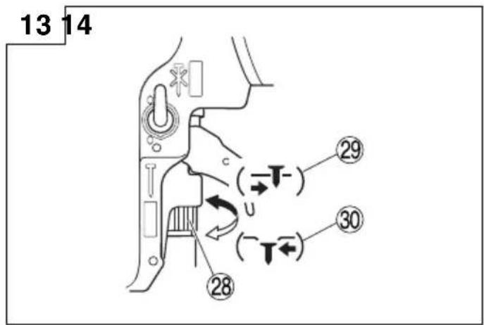
○ Adjusting the adjuster (Fig. 13)
Carry out test driving. If the nails are too deep, turn the adjuster to the shallow side ( -mark). If the nail depth is too shallow, turn the adjuster to the deep side ( -mark) (See Fig. 13, 14). Depth is changed 1 mm with each rotation of the adjuster.
NOTE
When adjusting the adjuster, it does not rotate more than 3 mm from the deepest point where a nail goes down. Do not rotate the adjuster by force beyond that point.
☐ The nail-driving depth can also be adjusted by changing the air pressure used. Carry this out together with movement of the adjuster. Using a high air pressure that does not match the nail-driving resistance will shorten the life of this nailer.
6. How to use nosecap CAUTION
Remove the hose from the nailer and release the compressed air before installing or removing the nosecap to prevent accidental nail ejection.
○ Attach the nose cap on the tip of the push lever when you wish to protect the surface of wood, etc., from scratches.
(1) Attaching and detaching nose cap
The nose cap can be attached by simply pressing it into the push lever.
Press it in until a convex part inside the nose cap enters into a hole of the push lever. (Fig. 15)
For removal, insert a thin rod such as a screw driver into the gap on the back of the push lever, and then pull it out.
(2) Safekeeping of nose cap
Put the removed nose cap in a space behind the magazine for safekeeping. (Fig. 16)
INSPECTION AND MAINTENANCE
CAUTION
Be sure to disconnect the hose during cleaning jams, inspection, maintenance and cleaning.
1. Countermeasure for nail jamming
(1) Remove the nail roll from the magazine, open the nail guide, insert a rod into the outlet and tap the rod with a hammer (Fig. 17).
(2) Remove the jammed nail with slotted screwdriver (Fig. 18).
(3) Cut off the defective part of the steel wire which links the nails with cutting nippers, correct the deformation, then load the nail roll in the magazine.
(4) In case of frequent jams, consult the Authorized Service Center from which you bought this machine.
2. Check on mounting screws for each part
At regular intervals check every part for loose mounting screws and whether or not there are any air leaks. Retighten any loose screws. Operating the equipment with loose screws untightened will incur a hazard.
3. Inspecting the push lever
Check if the push lever can slide smoothly (Fig. 19). Clean up the sliding area of the push lever and use the provided oil for lubrication from time to time. Lubrication enables smooth sliding and simultaneously serves to prevent the formation of rust.
4. Inspecting the feeders
(1) Occasionally clean the knob sliding part and then apply the recommended oil (See Fig. 19).
(2) Open the nail guide and remove dust, etc., as shown in Fig. 20. Apply lubricant to the sliding groove of the feeder and shaft. Check the nail stopper (A) and nail stopper (B) slide smoothly by pushing them with your finger.
(3) Also, apply the recommended oil to the feeding sur face of the nose and nail guide after cleaning. This promotes smooth operation and retards corrosion.
CAUTION
Check for smooth movement of the feeders and stoppers before use. If movement is uneven, nails could be fired at an irregular angle, presenting a hazard to the operator and others nearby.
5. Inspect the Trigger
Periodically clean the sliding parts of the trigger, and make sure that the trigger moves smoothly (Fig. 21).
6. Inspecting the muffler
This Nailer has a built-in muffler in the exhaust to reduce noise and stirred-up dust during exhaust.
When the mesh of the muffler is filled or the muffler is damaged, replace the muffler with a new one. To replace the muffler, contact our Authorized Service Center (Fig. 22).
7. Inspecting the magazine
Clean the magazine. Remove dust of wooden chips which may have accumulated in the magazine.
8. Storing
- When not in use for an extended period, apply a thin coat of the lubricant to the steel parts to avoid rust.
- Do not store the Nailer in a cold weather environment. Keep the Nailer in a warm area.
When not in use, the Nailer should be stored in a warm and dry place.
Keep out of reach of children.
CAUTION
In the operation and maintenance of power tools, the safety regulations and standards prescribed in each country must be observed.
COMPRESSOR
CAUTION
When the maximum, operating pressure of the air compressor exceeds 23 bar (320 psi), be sure to provide a reducing valve between the air compressor and nailer. Then, adjust the air pressure within the operating range of 12 – 23 bar (170 – 320 psi). If the air set is installed, lubrication is also possible, thus providing additional convenience.
APPLICABLE LUBRICANTS
| Type of lubricant | Name of lubricant |
| Recommended oil | SHELL TONNA |
| Motor oil | SAE10W, SAE20W |
| Turbine oil | ISO VG32 - 68(#90 - #180) |
Noise Information
Noise characteristic values in accordance with EN ISO 11148-13:2018
The typical A-weighted single-event sound power level
LwA, 1 s, d = 9 9. 5 dB
The typical A-weighted single-event emission sound
pressure level at work station LpA,1s,d=91.6\ dB
Uncertainty K: 2.5 dB (A)
These values are tool-related characteristic values and do not represent the noise development at the point of use. Noise development at the point of use will for example depend on the working environment, the workpiece, the workpiece support and the number of driving operations, etc.
Depending on the conditions at the workplace and the form of the workpiece, individual noise attenuation measures may need to be carried out, such as placing workpieces on sound-damping supports, preventing workpiece vibration by means of clamping or covering, adjusting to the minimum air pressure required for the operation involved, etc.
In special cases it is necessary to wear hearing protection equipment.
Vibration Information
The typical vibration characteristic value in accordance with EN ISO 11148-13:2018, 2000: 5.3 m/s 2
Uncertainty K = 1.5 m/s 2
This values is a tool-related characteristic value and does not represent the influence to the hand-arm-system when using the tool. An influence to the hand-arm-system when using the tool will for example depend on the gripping force, the contact pressure force, the working direction, the adjustment of energy supply, the workpiece, the workpiece support.
INSPECTION ET MANUTENTION
ATTENTION
OPTIONELE ACCESSOIRES
Siemensring 34, 47877 willich, Germany
Tel: +49 2154 49930
Fax: +49 2154 499350
URL: http://www.hikoki-powertools.de
Hikoki Power Tools Netherlands B.V.
Brabanthaven 11, 3433 PJ Nieuwegein, The Netherlands
Tel: +31 30 6084040
Fax: +31 30 6067266
URL: http://www.hikoki-powertools.nl
Hikoki Power Tools (U.K.) Ltd.
Precedent Drive, Rooksley, Milton Keynes, MK 13, 8PJ,
United Kingdom
Tel: +44 1908 660663
Fax: +44 1908 606642
URL: http://www.hikoki-powertools.uk
Hikoki Power Tools France S.A.S.
Hikoki Power Tools Belgium N.V./S.A.
Koningin Astridlaan 51, B-1780 Wemmel, Belgium
Tel: +32 2 460 1720
Fax: +32 2 460 2542
URL http://www.hikoki-powertools.be
Hikoki Power Tools Italia S.p.A
Via Piave 35, 36077, Altavilla Vicentina (VI), Italy
Tel: +39 0444 548111
Fax: +39 0444 548110
URL: http://www.hikoki-powertools.it
Hikoki Power Tools Ibérica, S.A.
C/ Puigbarral, 26-28, Pol. Ind. Can Petit, 08227 Terrassa
(Barcelona), Spain
Tel: +34 93 735 6722
Fax: +34 93 735 7442
URL: http://www.hikoki-powertools.es

| English Nederlands | ||
| EC DECLARATION OF CONFORMITYWe declare under our sole responsibility that High Pressure Coil Nailer, identified by type and specific identification code *1), is in conformity with all relevant requirements of the directives *2) and standards *3). Technical fi le at *4) – See below.The European Standard Manager at the representative office in Europe is authorized to compile the technical fi le.The declaration is applicable to the product affi xed CE marking. | EC VERKLARING VAN CONFORMITEITWij verklaren onder onze eigen verantwoordelijkheid dat Hoge druk spijkerapparaat, geïdentificeerd door het type en de specifieke identificatiecode*1), voldoet aan alle relevante bepalingen van de richtlijnen*2) en normen*3). Technische documentatie bij*4) – zie onder.De Europese Normen Manager bij de vertegenwoordiging in Europa is gemachtigd om het technisch dossier samen te stellen.Deze verklaring is van toepassing op producten voorzien van de CE-markeringen. | |
| Deutsch Español | ||
| EG-KONFORMITÄTSERKLÄRUNGWir erklären in alleiniger Verantwortung, dass der durch den Typ und den spezifischen Identifizierungscode *1) identifizierte Hochdruck-Coil-Nagler allen einschlägigen Bestimmungen der Richtlinien *2) und Normen *3) entspricht. Technische Unterlagen unter *4) – Siehe unten.Die Leitung der repräsentativen Behörde für europäische Normen und Richtlinien ist berechtigt, die technischen Unterlagen zusammenzustellen.Die Erklärung gilt für die an dem Produkt angebrachte CE-Kennzeichnung. | DECLARACIÓN DE CONFORMIDAD DE LA CEDeclaramos bajo nuestra única responsabilidad que la Clavadora de alta presion, identificada por tipo y por código de identificación específico *1), está en conformidad con todas las disposiciones correspondientes de las directivas *2) y de las normas *3). Documentación técnica en *4) – Ver a continuación.El Director de Normas Europeas en la oficina de representación en Europa está autorizado para elaborar el expediente técnico.La declaración se aplica al producto con marcas de la CE. | |
| Français Português | ||
| DECLARATION DE CONFORMITE CENous déclarons sous notre entière responsabilité que le Cloueur rouleaux haute pression, identifié par le type et le code d'identification spécifique *1) est en conformité avec toutes les exigences applicables des directives *2) et des normes *3). Dossier technique en *4) - Voir ci-dessous.Le Gestionnaire des normes européennes du bureau de représentation en Europe est autorisé à constituer le dossier technique.Cette déclaration s'applique aux produits désignés CE. | DECLARAÇÃO DE CONFORMIDADE CEDeclaramos, sob nossa única e inteira responsabilidade, que a Clavadora pressão alta, identificada por tipo e código de identificação especifici co *1), está em conformidade com todos os requisitos relevantes das diretivas *2) e normas *3). Ficheiro técnico em *4)-Consulte abaixo.O Gestor de Normas Europeias no escritório de representação na Europa está autorizado a compilar o fi cheiro técnico.A declaração aplica-se aos produtos com marca CE. | |
| Italiano | ||
| DICHIARAZIONE DI CONFORMITÀ CEDichiariamo sotto la nostra esclusiva responsabilità che la chiodatrice ad alta pressione, identificata dal tipo e dal codice identificativo specifico *1), è conforme a tutti i requisiti pertinenti delle direttive *2) e degli standard *3). Documentazione tecnica presso *4) – Vedere sotto.Il gestore delle norme europee presso l'ufficio di rappresentanza in Europa è autorizzato a compilare il fascicolo tecnico.La dichiarazione è applicabile ai prodotti cui sono applicati i marchi CE. | ||
| *1) NV100H C337633B*2) 2006/42/ECC*3) EN ISO 11148-13:2018 | ||
| *4) Representative offi ce in EuropeHikoki Power Tools Deutschland GmbHSiemensring 34, 47877 Willich, GermanyHead offi ce in JapanKoki Holdings Co., Ltd.Shinagawa Intercity Tower A, 15-1, Konan 2-chome,Minato-ku, Tokyo, Japan | 31. 10. 2019Naoto YamashiroEuropean Standard Manager31. 10. 2019A. NakagawaCorporate Offi cer | |
Koki Holdings Co., Ltd.

- GENERAL OPERATIONAL PRECAUTIONS
- WARNING
- PRECAUTIONS ON USING NAILER
- PROTECT YOUR EARS AND HEAD
- PAY ATTENTION TO THOSE WORKING CLOSE TO YOU
- NEVER POINT THE NAIL OUTLET TOWARDS PEOPLE
- BEFORE USING THE POWER TOOL, CHECK THE PUSH LEVER
- USE SPECIFI ED NAILS ONLY
- DO NOT MODIFY THE FASTENER DRIVING TOOL
- BE CAREFUL WHEN CONNECTING THE HOSE
- COMPLETELY CLOSE THE NAIL GUIDE AND DO NOT OPEN IT DURING OPERATION
- PRESS THE NAIL OUTLET FIRMLY AGAINST THE MATERIAL TO BE NAILED
- KEEP HANDS AND FEET AWAY FROM THE FIRING HEAD WHEN USING
- DURING OPERATION, DEBRIS FROM WORKPIECE AND FASTENING/COLLATION SYSTEM MAY BE DISCHARGED
- BEWARE OF THE TOOL'S KICKBACK
- TAKE CARE WHEN NAILING THIN BOARDS OR THE CORNERS OF WOOD
- SIMULTANEOUS NAILING ON BOTH SIDES OF THE SAME WALL IS DANGEROUS
- DO NOT USE THE POWER TOOL ON SCAFFOLDINGS, LADDERS
- DO NOT DISCONNECT THE HOSE WITH YOUR FINGER ON THE TRIGGER
- DISCONNECT THE HOSE AND TAKE OUT ANY NAILS LEFT IN THE MAGAZINE AFTER USE
- NAIL SELECTION
- STANDARD ACCESSORIES
- OPTIONAL ACCESSORY
- APPLICATIONS
- NOTE
- CHECK ON SAFETY
- CAUTION
- BEFORE USE
- CHECK THE AIR PRESSURE
- LOCK MECHANISM OF THE TRIGGER
- LUBRICATION
- LOAD NAILS
- HOW TO DRIVE NAILS
- DRIVING NAILS INTO STEEL PLATING
- DRIVING NAILS INTO CONCRETE CAUTION
- ADJUSTING THE NAIL-DRIVING DEPTH
- HOW TO USE NOSECAP CAUTION
- INSPECTION AND MAINTENANCE
- COUNTERMEASURE FOR NAIL JAMMING
- CHECK ON MOUNTING SCREWS FOR EACH PART
- INSPECTING THE PUSH LEVER
- INSPECTING THE FEEDERS
- INSPECT THE TRIGGER
- INSPECTING THE MUFFLER
- INSPECTING THE MAGAZINE
- STORING
- COMPRESSOR
- NOISE INFORMATION
- VIBRATION INFORMATION
- INSPECTION ET MANUTENTION
- ATTENTION
- OPTIONELE ACCESSOIRES
- HIKOKI POWER TOOLS NETHERLANDS B.V
- HIKOKI POWER TOOLS (U.K.) LTD
- HIKOKI POWER TOOLS FRANCE S.A.S
- HIKOKI POWER TOOLS BELGIUM N.V./S.A
- HIKOKI POWER TOOLS ITALIA S.P.A
- HIKOKI POWER TOOLS IBÉRICA, S.A
- KOKI HOLDINGS CO., LTD
Brand : HiKOKI
Model : NV100H
Category : Stapler